


 下载:
下载:


-
广角镜头广泛用于各种场景成像,例如机器视觉,大场景观测[1, 2]、监控和医学内窥成像系统等等。然而,广角镜头成像存在较大畸变。图像畸变导致无法精准确定图像中物体的几何位置和尺寸,甚至在图像识别过程中造成误判。因此,进行畸变校正显得尤为重要。
针对镜头的几何畸变,Brown[3]提出了径向畸变,偏心畸变和薄透镜畸变。其中,径向畸变为主要的畸变。大多数传统的畸变校正方法使用校正模板,一般包括两种方法。第一种是铅垂线算法,使用单个校正模板[4],模板中需要包含足够多的直线。另一种是多视图[5]校正方法。以上两种方法都需要建立畸变模型,通过提取大量的特征点或者特征线来决定畸变模型的畸变系数,然后再根据获得的畸变模型对整幅图像进行校正,精确的畸变模型获得显得非常重要。
条纹图相位分析技术,是一种高精度、自动、全场分析条纹形变分布的技术,广泛用于各种基于光学条纹图的测量技术中,如干涉测量[6]、数字全息测量[7]、莫尔条纹测量[8]、条纹投影轮廓术[9]等。目前已发展出许多条纹相位分析方法,主要分为两类:一类是基于单幅条纹图的方法,特点是可以进行动态分析,但分析精度相对较低;另一类是基于多幅条纹图的方法,特点是分析精度高但在动态分析方面有限制。杨初平等人提出了基于单幅条纹图分析的镜头畸变校正方法[10, 11],不需要通过特征点或特征线来确定畸变模型,可以直接计算畸变图像中每个像素点的畸变量。基于单幅条纹图的分析技术,主要有傅里叶变换法[12]、窗口傅里叶变换法[13]和小波变换法[14]等。一般认为这些基于单幅条纹图的相位解调精度要低于基于多幅条纹图的相移方法。对于广角镜头拍摄的液晶屏显示的条纹图,条纹图的灰度分布存在一个类似高斯分布的调制(图像中心区域亮,边缘四周暗),这种调制对傅里叶变换法的相位解调精度将产生影响,而对于基于多幅条纹图的相移法[15]将不受影响。另外,杨初平等人提出的方法采用投影条纹[10]或印刷条纹方式[11]。投影条纹方式可能引入投影透镜畸变,将影响成像透镜的校正精度。投影方式,一般投影装置和拍摄装置设置在投影屏的同侧,由于广角镜头的视角大而投影屏尺寸有限,拍摄时需要广角镜头靠近投影屏,会导致拍摄装置遮挡投影光线产生阴影,从而出现校正盲区;而印刷条纹方式不容易制作大面积的无畸变标准条纹,且不便进行相移分析。
为了实现更高精度的畸变校正,文中提出了一种基于四步相移条纹图相位分析的广角镜头畸变校正方法。利用液晶平板显示器显示四幅相移量为π/2的余弦条纹图作为校正模板,然后被广角镜头成像系统拍摄,获得四幅畸变条纹图像。使用四步相移算法进行相位解调,以获得径向畸变条纹图像的相位分布。利用图像中心无畸变的相位值进行数值拟合得到径向无畸变条纹的相位分布,作为求解畸变相位的基准,获得径向畸变相位分布。径向畸变与拍摄景深无关,仅决定于广角镜头成像系统的视场角,文中通过实验也证明了这一特性。理论分析和实验结果表明,提出基于四步相移条纹图相位分析的镜头畸变校正方法简单,有效,具有广泛应用前景。
-
图1为实验装置示意图,液晶平板显示器LCD显示标准余弦条纹图,广角镜头相机拍摄条纹图,相机的光轴垂直液晶显示器平板。拍摄到的畸变条纹图,如图2所示,图中虚线表示无畸变情况下的条纹图,实线表示畸变条纹图,C、D分别表示无、有畸变时场景中同一物点的像点位置,那么CD为该物点像的畸变量。

图 1 实验装置
Figure 1. Experimental apparatus

图 2 畸变示意图
Figure 2. Distortion schematic diagram
假设无畸变图像为
$C(x,y)$ ,畸变图像为$D(x',y')$ 。$(x,y)$ 和$(x',y')$ 分别是图像畸变前后对应的坐标对。两个坐标的关系可以表示为:$$\left\{ \begin{aligned} & x = {o_1}(x',y') \\ & y = {o_2}(x',y') \end{aligned} \right.$$ (1) 只需要用畸变前后图像上目标点到中心点
$({x_0},{y_0})$ 的距离来计算整张图像的畸变量。畸变图像坐标与无畸变图像坐标之间的关系可以简单地表示为:$$ r = o(r') $$ (2) 其中
$r(x,y) = \sqrt {{{(x - {x_0})}^2} + {{(y - {y_0})}^2}} $ 和$r'(x',y') = $ $ \sqrt {{{(x' - {x_0})}^2} + {{(y' - {y_0})}^2}} $ 是无畸变图像和畸变图像上点$(x,y)$ ,$(x',y')$ 分别到其图像中心的距离。如果能建立无畸变图像坐标与畸变图像坐标之间的映射关系,就可以实现图像的校正。假设
$C[r(x,y)]$ 是校正后图像点$(x,y)$ 的灰度值,该灰度值等于畸变图像点$(x',y')$ 上的灰度值$D[r'(x',y')]$ :$$ C[r(x,y)] = D[r'(x',y')] = D[r(x,y) + \Delta r] $$ (3) 式中:
$\Delta r$ 是相应的径向畸变量。因为图像的径向畸变是关于图像中心圆对称的,只需确定从图像中心点开始沿正方向的径向畸变量分布,便可进行图像畸变校正。需要留意的是广角镜头的径向畸变是径向压缩,校正后图像的坐标
$(x,y)$ 要大于校正前对应的畸变坐标$(x',y')$ ,也就是校正后图像的像素数要大于校正前图像的像素数,或者计算得到的$(x',y')$ 坐标不是整数,因此,有必要对那些多出的像素点或非整数点进行灰度插值。使用双线性插值算法,可以克服灰度不连续性的问题。假设${x_1}$ 和${y_1}$ 分别是小于或等于$x'$ 和$y'$ 的最近整数,而且,$(x',y')$ 落在$({x_1},{y_1})$ ,$({x_1} + 1,{y_1})$ ,$({x_1},{y_1} + 1)$ 和$({x_1} + 1,{y_1} + 1)$ 这四个像素构成的二维区域之间,双线性插值算法的计算公式为:$$ \begin{split} C[r(x,y)] =\; & (1 - \alpha )(1 - \beta )D[r({x_1},{y_1})] + \\ & \alpha (1 - \beta )D[r({x_1} + 1,{y_1})] + \\ & (1 - \alpha )\beta D[r({x_1},{y_1} + 1)] +\\ & \alpha \beta D[r({x_1} + 1,{y_1} + 1)] \end{split} $$ (4) 式中:
$\alpha = x' - {x_1}$ ;$\beta = y' - {y_1}$ 。 -
四幅相移量分别为0,π/2,π,3π/2的纵向余弦条纹图作为校正模板。一般情况下,广角镜头的径向畸变是中心圆对称的,只需要利用广角镜头相机拍摄到的畸变条纹图的中心行
$(y = {y_0})$ 条纹来测量整幅图像的径向畸变。中心行条纹可表示为:$$ \begin{split} {I_1}(x,{y_0}) =\;& G(x,{y_0})\{ A(x,{y_0}) + \\ & B(x,{y_0})\cos [\varphi (x,{y_0})]\}\end{split} $$ (5) $$ \begin{split} {I_2}(x,{y_0}) =\; & G(x,{y_0})\{ A(x,{y_0}) + \\ & B(x,{y_0})\cos [\varphi (x,{y_0})+\frac{{\text{π}}}{2}]\} \end{split} $$ (6) $$ \begin{split} {I_3}(x,{y_0}) =\;& G(x,{y_0})\{ A(x,{y_0}) + \\ & B(x,{y_0})\cos [\varphi (x,{y_0})+{\text{π}}]\} \end{split} $$ (7) $$ \begin{split} {I_4}(x,{y_0}) =\; & G(x,{y_0})\{ A(x,{y_0}) + \\ & B(x,{y_0})\cos [\varphi (x,{y_0})+\frac{{3{\text{π}}}}{2}]\} \end{split} $$ (8) 式中:
$G(x,{y_0})$ 为幅度调制函数;$A(x,{y_0})$ 为背景光强度;$B(x,{y_0})/A(x,{y_0})$ 为条纹图的对比度。$\varphi (x,{y_0})$ 为径向畸变条纹相位。通过对四张条纹图的中心行使用四步相移法进行相位解调,可以获得径向畸变条纹图的包裹相位为:$$\varphi (x,{y_0}) = \arctan \left[ {\frac{{{I_4}(x,{y_0}) - {I_2}(x,{y_0})}}{{{I_1}(x,{y_0}) - {I_3}(x,{y_0})}}} \right]$$ (9) 通过使用解包裹算法,可以获得实际的径向畸变条纹图的相位值。
为了测量像素点的畸变量,必须以无畸变的条纹图作为基准。
由于镜头拍摄的中心区域的图像几乎没有畸变。可以根据计算得到的径向畸变条纹图的相位分布的中心位置像素点的相位值拟合一个径向无畸变条纹图的相位分布作为基准。假设径向无畸变条纹图的相位分布为:
$$ {\varphi _{{\rm{undistorted}}}}(x,{y_0}) = kx + {\varphi _0} $$ (10) 式中:
$k{\rm{ = 2}}{\text{π}}{f_0}$ 和${\varphi _0}$ 分别为直线拟合的一次系数和常数系数,${f_0}$ 为基频。径向畸变相位可以表示为:$$ \Delta \varphi (x,{y_0}) = \varphi (x,{y_0}) - {\varphi _{{\rm{undistorted}}}}(x,{y_0}) $$ (11) 根据图2所示的几何结构,径向畸变量
$\Delta r$ 和其对应的径向畸变相位$\Delta \varphi $ 可以表示为:$$ \Delta r = \overline {CD} = \frac{{\Delta \varphi }}{{2{\text{π}}{f_0}}} $$ (12) 所以,使用条纹图相位分析的方法,可以确定径向畸变量分布。最后,根据公式(3)和公式(4)可以对畸变图像进行校正。
-
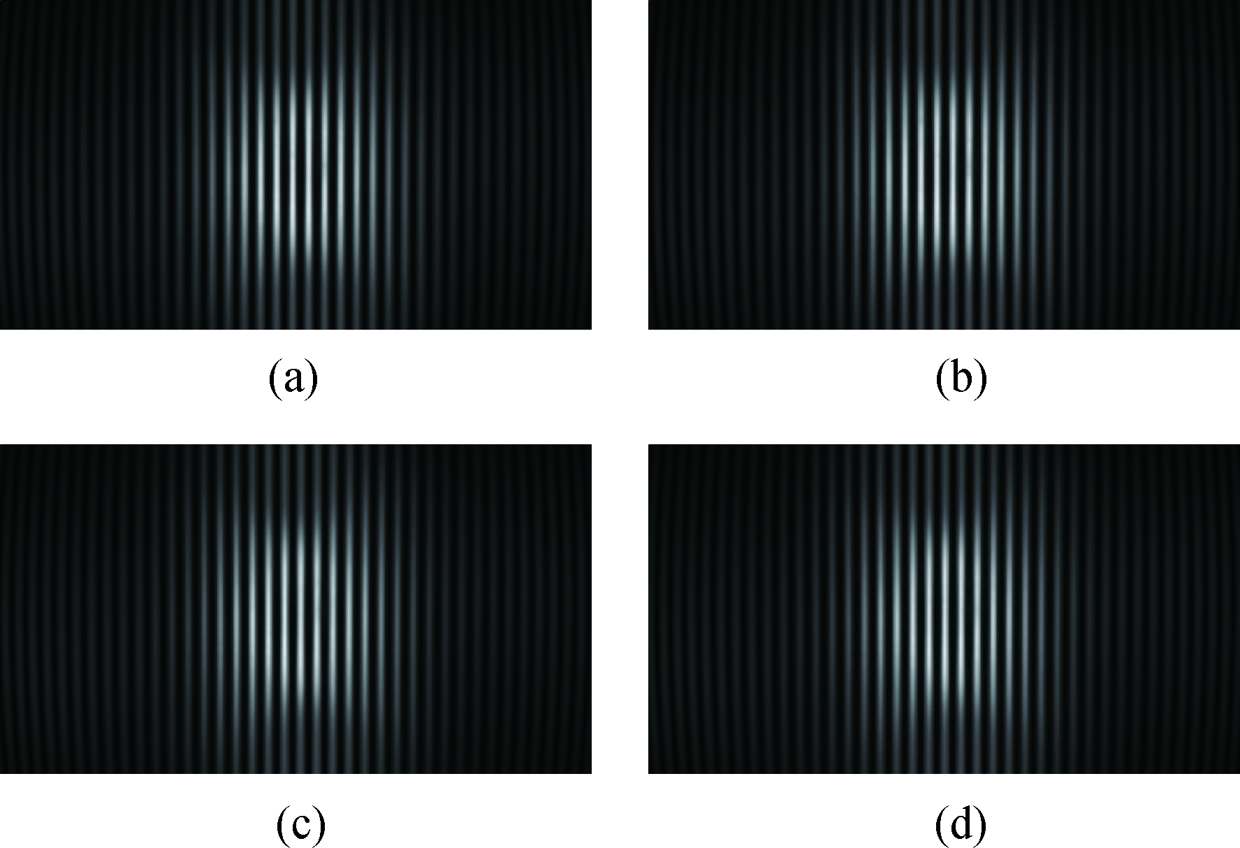
利用图1所示的装置进行实验。用一个将被校正的广角镜头(Theia MY125M,FOV 137°,景深:10 cm到无穷远)用来捕获49 in(1 in=2.54 cm)晶显示器(FunTV D49Y,1 100 mm×635 mm)上显示的四幅相移量为0,π/2,π,3/2π的余弦条纹图,拍摄得到如图3所示四幅畸变条纹图,畸变条纹图案的大小为1 920×1 080像素。实验中,根据拍摄条纹的上下左右的对称性(考察上下对称时显示横条纹),仔细调整拍摄与显示装置,使得相机的光轴垂直液晶显示器平板。仔细调整广角镜头成像系统与液晶显示器,使得拍摄获得的条纹方向沿着y方向。用计算机对图3所示的拍摄的图像进行数值分析,分析过程可描述为以下几步。

图 3 拍摄到的四幅不同相位的畸变条纹图。(a)相移量为0;(b)相移量为π/2;(c)相移量为π;(d) 相移量为3π/2
Figure 3. Four captured distorted fringe-patterns. (a) With phase shift of 0; (b) with phase shift of π/2; (c) with phase shift of π; (d) with phase shift of 3π/2
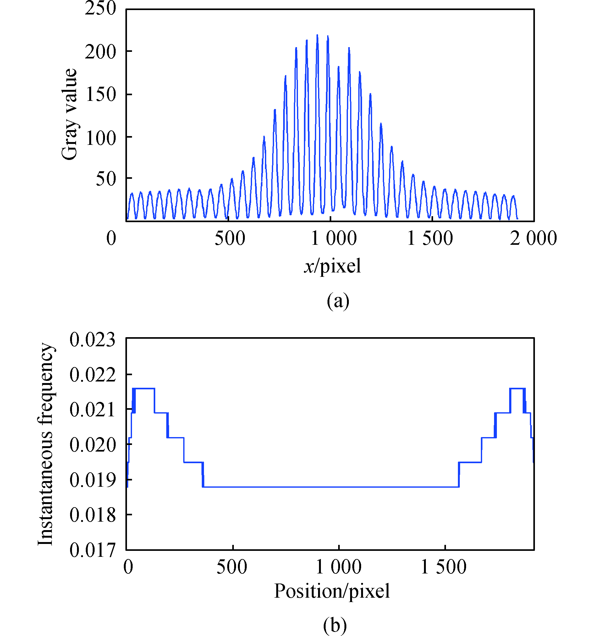
步骤一:采用四步相移法对四张条纹图的中间行进行相位解调,解包裹后获得径向畸变条纹图的相位分布。为了去除噪声,采用三次多项式拟合对径向畸变条纹图的相位分布进行平滑处理。图4(a)显示了图3(b)的中间行的灰度分布,从该图可以发现,中心区域的幅值远高于两侧,明显存在一个类似高斯分布的调制。在该灰度分布中,可以看到中心左右两侧的条纹周期是一致的,而且几乎关于中心对称,因此得知,相机的光轴已基本垂直液晶显示器。采用傅立叶分析时,相位分析会引入较大的误差。四步相移法由于其最佳的空间区域性,可以提供高精度的畸变条纹相位分布分析。这是测量图像畸变的关键步骤。

图 4 条纹图中间行的灰度值分布(a)和瞬时频率(b)
Figure 4. Gray value distribution (a) and the instantaneous frequency (b) of the central row of the fringe-pattern
步骤二:数值拟合无畸变条纹图的相位分布。利用小波分析对畸变条纹图中间行进行瞬时频率分析,可以证明条纹图中间行的中心区域几乎不发生畸变。通过检测条纹图案的中间行的每个位置的小波系数的最大值,可以得到对应的瞬时频率,如图4(b)所示。图4(b)显示了图3(b)的中间行的中心区域的瞬时频率保持不变,所以这个区域几乎没有图像畸变。利用径向畸变条纹图相位分布中心无畸变的九个点的相位值,并根据公式(10)进行数值线性拟合,得到径向无畸变条纹图的相位分布。
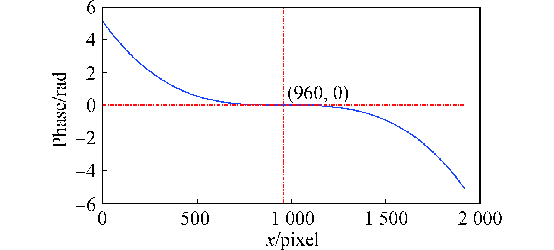
步骤三:根据公式(11)计算径向畸变相位分布,如图5所示的蓝色实线。由图5可以看出,径向畸变相位分布是关于光轴旋转近似对称的(图中x=960像素点为中心点)。理论上,可以使用沿着正方向的径向畸变相位来计算畸变量分布。但实际上径向畸变相位并不是完全的中心对称,由于实际光路并不是理想状态,有微小差异。因此,负方向的径向畸变相位沿畸变相位的中心对称地旋转,然后再与正方向的径向畸变相位叠加求平均,可以得到正方向的平均径向畸变相位,从而可以计算畸变量分布。
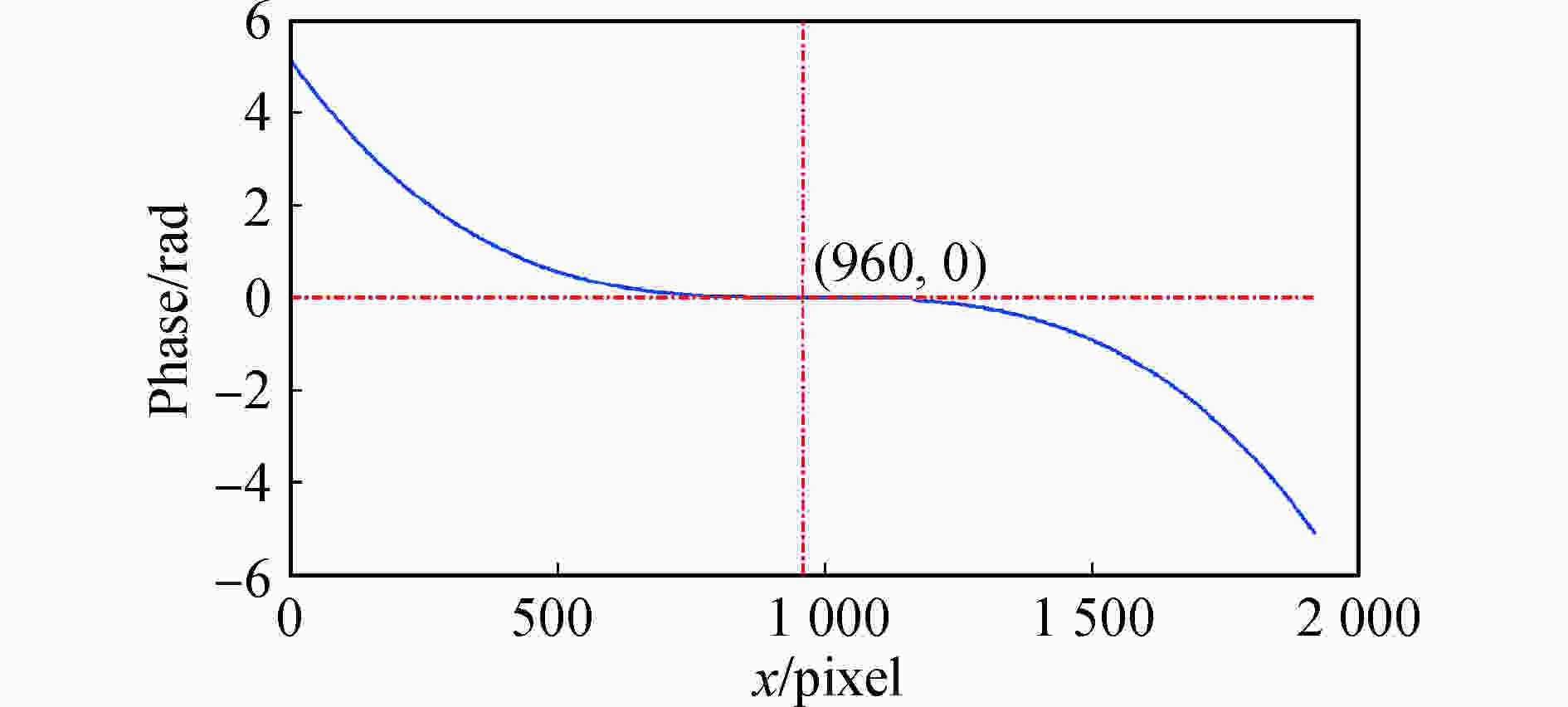
图 5 径向畸变相位分布
Figure 5. Radial distorted phase distribution
步骤四:将正方向的平均径向畸变相位分布扩展到更大的区域进行图像校准,因为图像校正最大的计算距离是畸变图像对角线的一半,为1 102像素。所以,利用三次多项式拟合来扩展径向调制相位。
步骤五:根据公式(12)可以计算径向畸变量分布。假设径向畸变为关于图像中心点圆对称,所以根据径向畸变量分布,畸变图像每个像素点的畸变量可以计算得到。通过双线性插值算法,根据公式(3)和公式(4),可以对畸变图像进行校正。
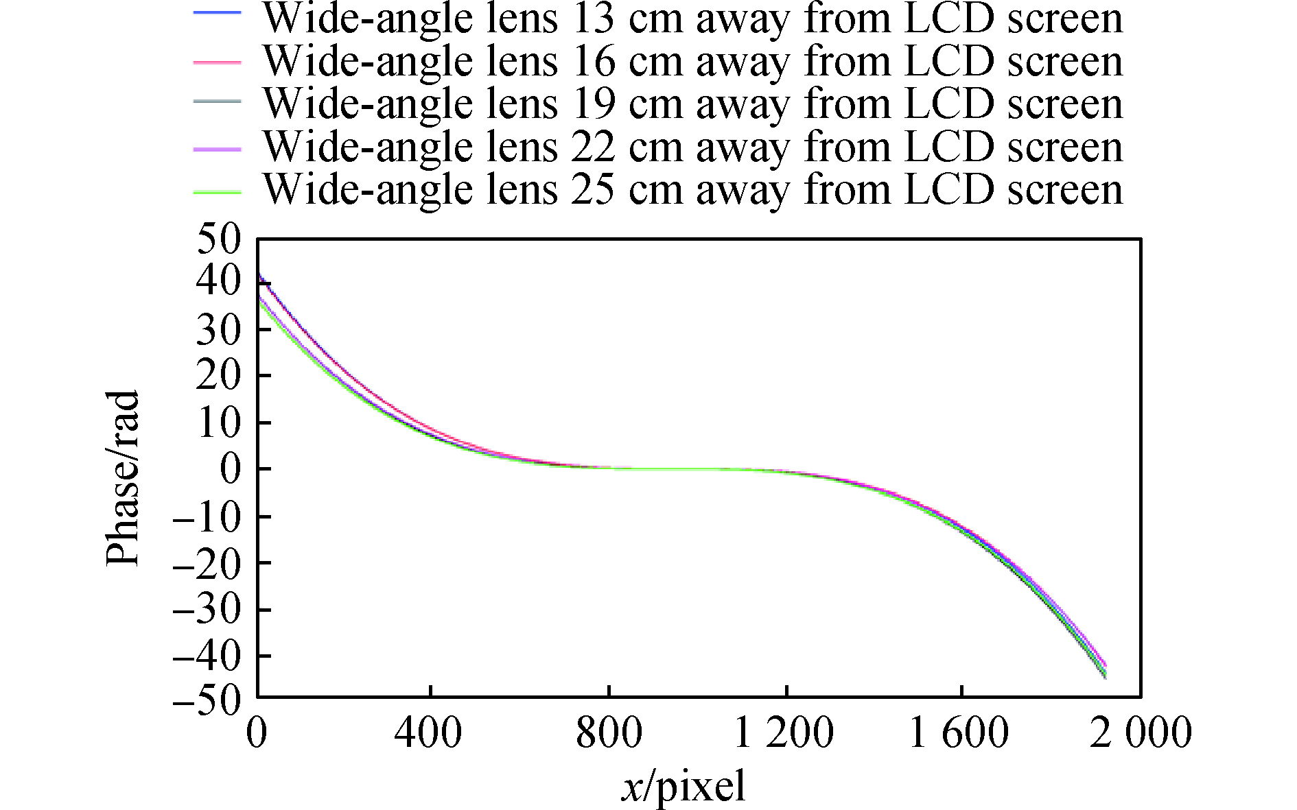
为了验证了广角镜头的景深对径向畸变量分布的影响,通过设置广角镜头到液晶显示器不同距离进行径向畸变相位分布测量。广角镜头到液晶显示器的记录距离由步进电机控制,分别为13 cm、16 cm、19 cm、22 cm和25 cm。图6显示了用提出方法计算的相应距离的径向畸变量分布。可以发现不同拍摄距离对应的畸变量分布几乎是一致的。因此,可以得出结论,图像的径向畸变量与三维场景中不同物体的景深无关,它取决于像素点到图像平面中心的距离,即与广角镜头成像系统的视场角有关,距离越大,径向畸变量越大。
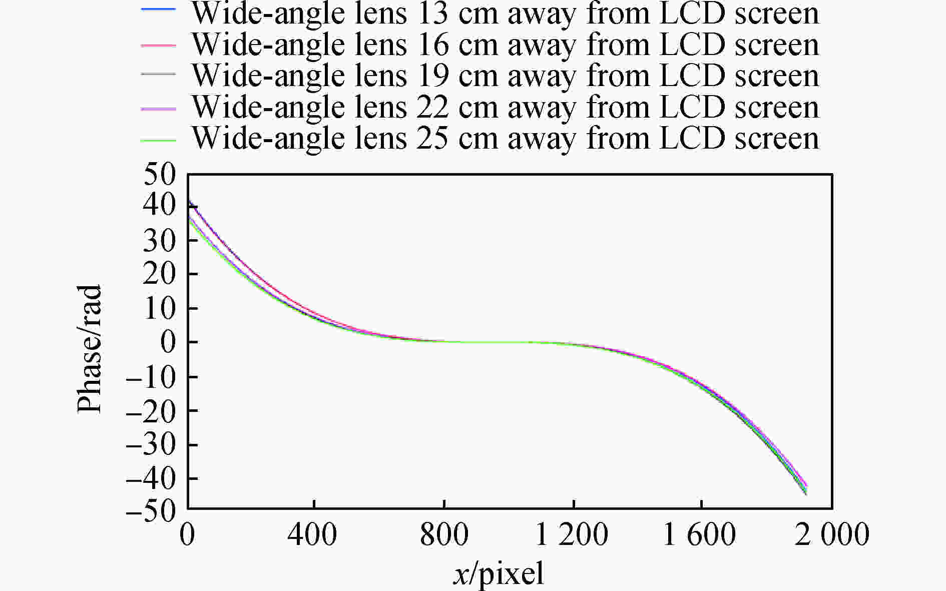
图 6 记录距离分别为13、16、19、22、25 cm的径向畸变量分布
Figure 6. Radial distortion distribution according to the recording distance of 13, 16, 19, 22, 25 cm
最后利用畸变校正好的广角镜头相机,对使用棋盘格、远距离和近距离的室外场景作为实验中广角镜头采集对象的图像进行了径向畸变的校正。图7展示了广角镜头拍摄的畸变的棋盘格图像和对应的校正后的图像,校正前后图像大小分别为1 920×1 080像素和2 063×1 161像素。为了定量评估畸变校正的效果,对图7(a)、(b)提取棋盘格角点,对校正前后的角点位置进行定量比较,如图8所示,其中红色“•”点表示畸变校正前的棋盘格图像的角点,蓝色“+”点表示校正后的棋盘格图像的角点。图8左上角第一个蓝色点和第一个红色点的距离为63.9像素。图9展示了畸变的远距离场景图和对应的校正后的图像;图10展示了畸变的近距离场景图和对应的校正图。实验结果表明,文中提出的方法有效地实现了畸变图像的校正。

图 7 畸变的棋盘格图像(a)和校正的棋盘格图像(b)
Figure 7. Distorted checkerboard image (a) and the calibrated checkerboard image (b)
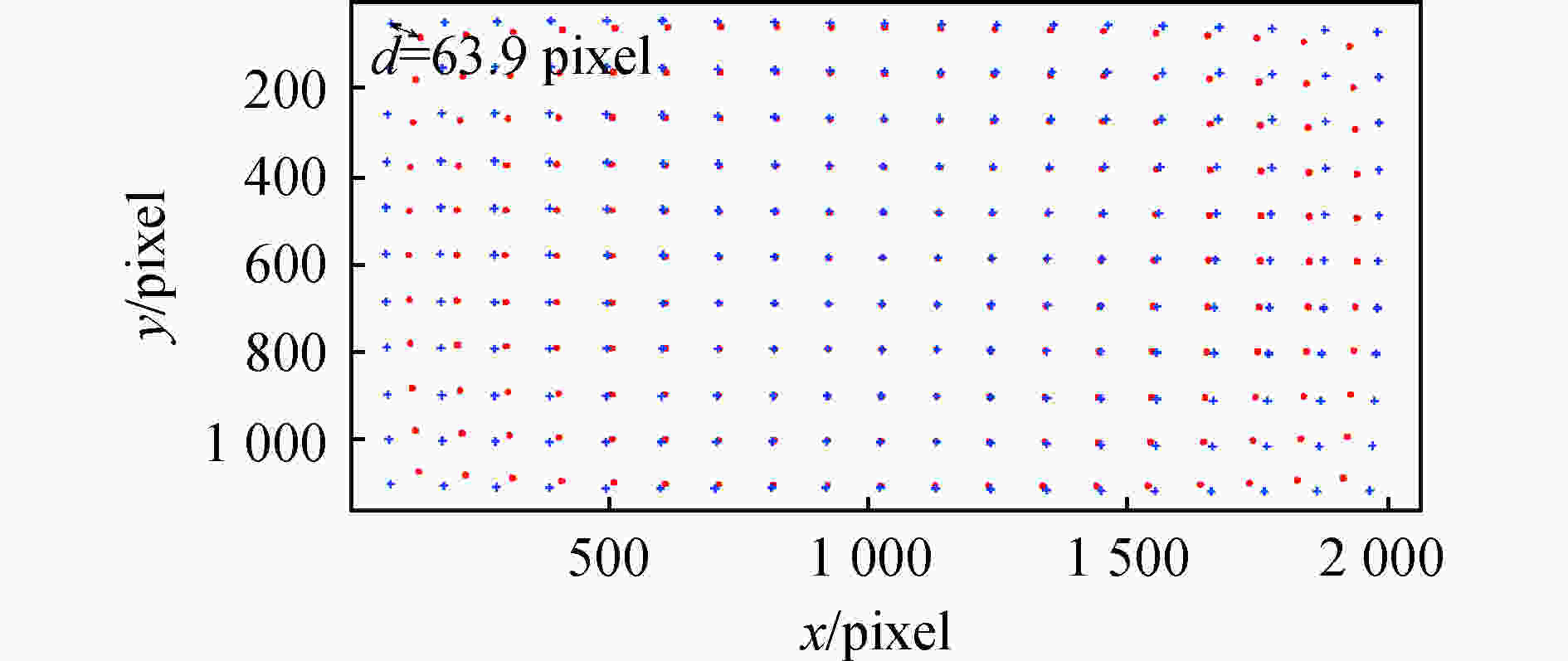
图 8 角点图,红色点表示校正前棋盘格图像的角点,蓝色点表示校正后棋盘格图像的角点
Figure 8. Corners image, the red points represent the corners of the distorted checkerboard image, and the blue points represent the corners of the calibrated checkerboard image

图 9 畸变的远景图(a)和校正的远景图(b)
Figure 9. Distorted image of a far-range scene (a) and the calibrated image of the far-range scene (b)

图 10 畸变的近景图(a)和校正的近景图(b)
Figure 10. Distorted image of a close-range scene (a) and the calibrated image of the close-range scene (b)
-
文中提出了一种基于条纹图相位分析的广角镜头畸变校正方法,具有以下优点和特色。
首先,该方法不需要提取特征点或者特征线建立精确畸变模型,可以直接计算畸变图像中的每个像素的畸变量,能够快速而有效地校正图像。
其次,文中采用四步相移法解调得到径向畸变条纹图的相位分布。四步相移法相对基于单幅条纹图的相位分析技术,可以提供更高精度的畸变条纹相位分布分析。
然后,根据径向畸变条纹图相位分布的中心无畸变相位点,采用数值线性拟合的方法获得径向无畸变条纹图的相位分布,作为校正的基准,该方法简单、有效、自动化程度高。
最后,实验装置中采用大尺寸液晶平板显示器显示标准余弦条纹,没有投影系统,它能很好地避免投影条纹方式可能引入的投影透镜畸变,影响校正精度,也避免了同侧投影可能出现的投影阴影,从而导致校正盲区。适用于广角镜头校正,且方便进行相移分析。
实验结果表明,提出的方法简单、有效、自动化程度高。
Wide-angle lenses distortion calibration using phase demodulation of phase-shifting fringe-patterns
-
摘要:
文中提出了一种基于相移条纹图相位分析的广角镜头畸变校正方法。首先,用大尺寸液晶平板显示器显示四幅相移量为π/2的余弦条纹图作为校正模板。然后,用广角镜头相机拍摄该校正模板,获得四幅畸变条纹图,使用四步相移算法解调径向畸变条纹图的相位分布。由于经广角镜头成像的图像中心区域几乎无畸变,利用图像中心无畸变的相位值进行数值拟合得到径向无畸变条纹图的相位分布,作为求解径向畸变相位的基准,也就是径向畸变相位分布可以根据径向畸变条纹图的相位分布与径向无畸变条纹图相位分布相减得到,再将畸变相位转换成实际的畸变量。提出的方法不需要通过特征点或特征线确定畸变模型,可以直接计算畸变图像中每个像素点的畸变量。实验结果表明,提出的方法简单、有效,具有广泛应用价值。
† 贡献相同Abstract:A distortion calibration method for wide-angle lens was proposed based on fringe-pattern phase analysis. Firstly, four standard cosine fringe-patterns with phase shift step of π/2, which were used as calibration templates, were shown on a large-size Liquid Crystal Display screen, and captured by the camera with wide-angle lens to obtain four distorted fringe-patterns. A four-step phase-shifting method was employed to obtain the phase distribution of the radial distorted fringe-pattern. There was no distortion within the central region of the image captured by the wide-angle lens, so the phase distribution of radial undistorted fringe-pattern, as a benchmark for computing radial distorted phase, could be acquired by performing numerical fitting by the central undistorted phase value of the distorted image. It means that the radial distorted phase distribution was computed by subtracting the phase distribution of radial distorted fringe-pattern from the phase distribution of radial undistorted fringe-pattern. Finally, the distorted phase was transformed into the actual distorted variables. There was no need to establish any kind of image distortion model by lots of characteristic points or lines. Furthermore, the radial distortion variable at each point of the distorted image can be determined by the proposed method. Experimental results show that the proposed method is simple, effective, and has wide application value.
-
Key words:
- distortion calibration /
- wide-angle lens /
- fringe-pattern phase analysis
-
图 3 拍摄到的四幅不同相位的畸变条纹图。(a)相移量为0;(b)相移量为π/2;(c)相移量为π;(d) 相移量为3π/2
Figure 3. Four captured distorted fringe-patterns. (a) With phase shift of 0; (b) with phase shift of π/2; (c) with phase shift of π; (d) with phase shift of 3π/2
图 4 条纹图中间行的灰度值分布(a)和瞬时频率(b)
Figure 4. Gray value distribution (a) and the instantaneous frequency (b) of the central row of the fringe-pattern
图 6 记录距离分别为13、16、19、22、25 cm的径向畸变量分布
Figure 6. Radial distortion distribution according to the recording distance of 13, 16, 19, 22, 25 cm
图 7 畸变的棋盘格图像(a)和校正的棋盘格图像(b)
Figure 7. Distorted checkerboard image (a) and the calibrated checkerboard image (b)
图 8 角点图,红色点表示校正前棋盘格图像的角点,蓝色点表示校正后棋盘格图像的角点
Figure 8. Corners image, the red points represent the corners of the distorted checkerboard image, and the blue points represent the corners of the calibrated checkerboard image
图 9 畸变的远景图(a)和校正的远景图(b)
Figure 9. Distorted image of a far-range scene (a) and the calibrated image of the far-range scene (b)
-
[1] Cai Ping, Li Xiaoyan, Tang Yujun, et al. Improved distortion correction method for spacial large aperture tracking cameras [J]. Optics and Precision Engineering, 2019, 27(10): 2272−2279. (in Chinese) doi: 10.3788/OPE.20192710.2272 [2] Lu Lijun, Liu Meng, Shi Ye. Correction method of image distortion of fisheye lens [J]. Infrared and Laser Engineering, 2019, 48(9): 0926002. doi: 10.3788/IRLA201948.0926002 [3] Brown D C. Close-range camera calibration [J]. Photogrammetric Engineering, 1971, 37: 855−866. [4] Kakani V, Kim H, Kumbham M, et al. Feasible self-calibration of larger field-of-view (FOV) camera sensors for the advanced driver-assistance system (ADAS) [J]. Sensors, 2019, 19(15): 3369. doi: 10.3390/s19153369 [5] Sun Junhua, Cheng Xiaoqi, Fan Qiaoyun. Camera calibration based on two-cylinder target [J]. Optics Express, 2019, 27(20): 29319−29331. doi: 10.1364/OE.27.029319 [6] Wang Xianmin, Liu Dong, Zang Zhongming, et al. The regularized phase tracking technique used in single closed interferogram phase retrieval [J]. Chinese Optics, 2019, 12(4): 719−730. (in Chinese) doi: 10.3788/co.20191204.0719 [7] Zhang Minmin, Tian Zhenyun, Xiong Yuankang, et al. Research on incoherent self-interference digital holography imaging technology [J]. Infrared and Laser Engineering, 2019, 48(12): 1224001. (in Chinese) doi: 10.3788/IRLA201948.1224001 [8] Zuo Yang, Long Kehui, Liu Jinguo, et al. Analysis and processing of Morié fringe signals based on non-uniform sampling [J]. Optics and Precision Engineering, 2015, 23(4): 1146−1152. (in Chinese) doi: 10.3788/OPE.20152304.1146 [9] Wang Jianhua, Yang Yanxi. Double N-step phase-shifting profilometry using color-encoded grating projection [J]. Chinese Optics, 2019, 12(3): 616−627. (in Chinese) doi: 10.3788/co.20191203.0616 [10] Yang Chuping, Weng Jiawen, Wang Jianwei. Distortion measurement and calibration technique based on phase analysis for carrier-fringe pattern [J]. Acta Photonica Sinica, 2010, 39(2): 316−319. (in Chinese) doi: 10.3788/gzxb20103902.0316 [11] Yang Chuping, Weng Jiawen, Liu Jianbin. Using dilating gabor transform to fringe analysis in distortion measurement [J]. Opto-Electronic Engineering, 2010, 37(1): 13−18. (in Chinese) [12] Takeda M, Mutoh K. Fourier transform profilometry for the automatic measurement of 3-D object shapes [J]. Applied Optics, 1983, 22(24): 3977−3982. doi: 10.1364/AO.22.003977 [13] Zhong Jingang, Zeng Huiping. Multiscale windowed Fourier transform for phase extraction of fringe patterns [J]. Applied Optics, 2007, 46(14): 2670−2675. doi: 10.1364/AO.46.002670 [14] Zhong Jingang, Weng Jiawen. Phase retrieval of optical fringe patterns from the ridge of a wavelet transform [J]. Optics Letters, 2005, 30(19): 2560−2562. doi: 10.1364/OL.30.002560 [15] Zuo Chao, Feng Shijie, Huang Lei, et al. Phase shifting algorithms for fringe projection profilometry: A review [J]. Optics and Lasers in Engineering, 2018, 109: 23−59. doi: 10.1016/j.optlaseng.2018.04.019 -

 点击查看大图
计量
- 文章访问数: 564
- HTML全文浏览量: 213
- 被引次数: 0


