


-
光学系统的像差一般由该系统的孔径和视场决定,大视场单孔径成像光学系统若孔径较大,则很难解决大孔径和大视场带来的像差问题。受启发于生物复眼的视场大、体积小、灵敏度高等视觉优势,人们提出了仿生复眼成像系统。复眼是自然界创造的高阶光学系统,由多个子眼组成,并有序分布在球面或椭球面上。目前,仿生复眼在国际上已经得到了广泛应用。
从20世纪中后期开始,H.B.Barlow、M.F.Land等学者对复眼的研究已经不仅仅停留在生物学角度,而是转向了光学方向。20世纪后期,科研工作者提出了许多具有代表性的仿生复眼结构,但是由于加工技术的不成熟,大量的仿生复眼系统仅停留在设计阶段,其中多以平面型复眼为主。进入21世纪,无论是精密加工技术还是复眼像质优化技术都取得了长足进步,科研人员也开始从平面型复眼研究逐渐转向曲面型复眼研究。
张红鑫科研团队提出一种曲面基底微透镜阵列的方法,应用于多孔径成像系统中来解决复眼系统中视场小、边缘视场成像质量差的问题。设计了两种类型的复眼结构——即单层曲面复眼和三层曲面复眼。虽然成像质量有所改善,但其最大视场只有88°,未能实现复眼系统的大视场优势,并且子透镜为圆型结构不能实现对球壳基底的最大利用率[1]。雷卫宁科研组对具有大视场的复眼成像探测系统结构进行了分析和研究,并设计了一款复眼结构,该系统由37个子眼组成,视场可达到150°,该系统虽然实现了复眼大视场的优点,但其复眼球壳的半径达到90 mm,子眼通光口径为6 mm[2]。
文中提出一种基于六边形子眼的紧密拼接结构的仿生复眼系统,由微透镜阵列、光阑阵列、转像系统三部分组成,其中微透镜阵列由六边形子眼紧密拼接构成,光阑阵列与转像系统紧随其后。整个复眼的口径仅为8.66 mm,视场角121°,具有视场大、体积小、质量轻等优点,若应用于机器视觉等相关领域,可实现系统的小型化和轻量化。
-
昆虫复眼可以看作是一种智能的多孔径光学系统,因其具有独特的面型结构,所以有着非常大的成像视场[3]。昆虫的多个子眼可以对同一物体成像,且具有高度集中的中枢神经系统,它还可以对运动中的物体进行高灵敏度的识别和定位[4]。
昆虫复眼的子眼数量从少于十个到数万不等,每个子眼都可以看作是一个单独的成像系统,通常包括角膜、晶锥和感杆束等。角膜在复眼的最外层,呈六边形分布,有着较高的折射率,类似于光学系统的透镜,起到保护内部结构的作用。角膜的下方是晶锥,呈圆锥状,它的形态可以随着入射光的强度变化而改变[5-7]。感杆束具有光敏特性,由多个感杆聚集而成。
根据成像原理的差异,自然界昆虫复眼类型可分为两种:并列型复眼和重叠型复眼[8]。并列型复眼的一个感杆束只能接收一个子眼的成像光束,而重叠型复眼则是一个感杆束接收多个子眼的成像光束。由于重叠型复眼的特殊结构,导致其像差很大,成像分辨率较低。因此,文中仅针对并列型复眼进行分析和研究。
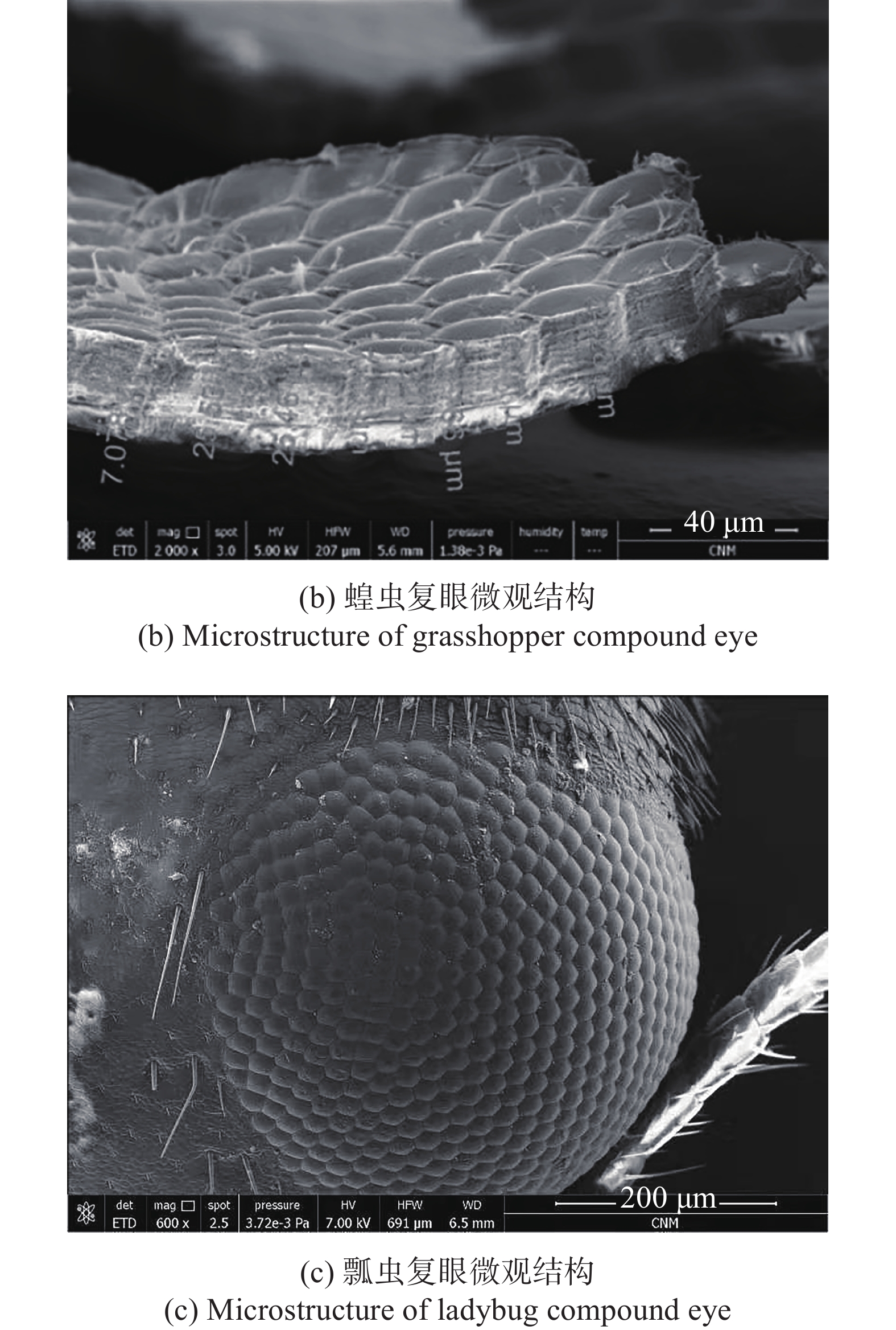
利用扫描电子显微镜,通过分析蜜蜂、蝗虫和瓢虫的复眼切片,对各复眼的表面形貌、子眼结构及其衔接方式进行研究,如图1所示。研究结果表明,以上昆虫的复眼形状均为球冠状,子眼均以六边形紧密拼接形式衔接,子眼口径约为20 μm。该结构为生物进化过程中优胜劣汰的自然选择结果,也为仿生复眼系统的设计提供了理论支撑[9]。

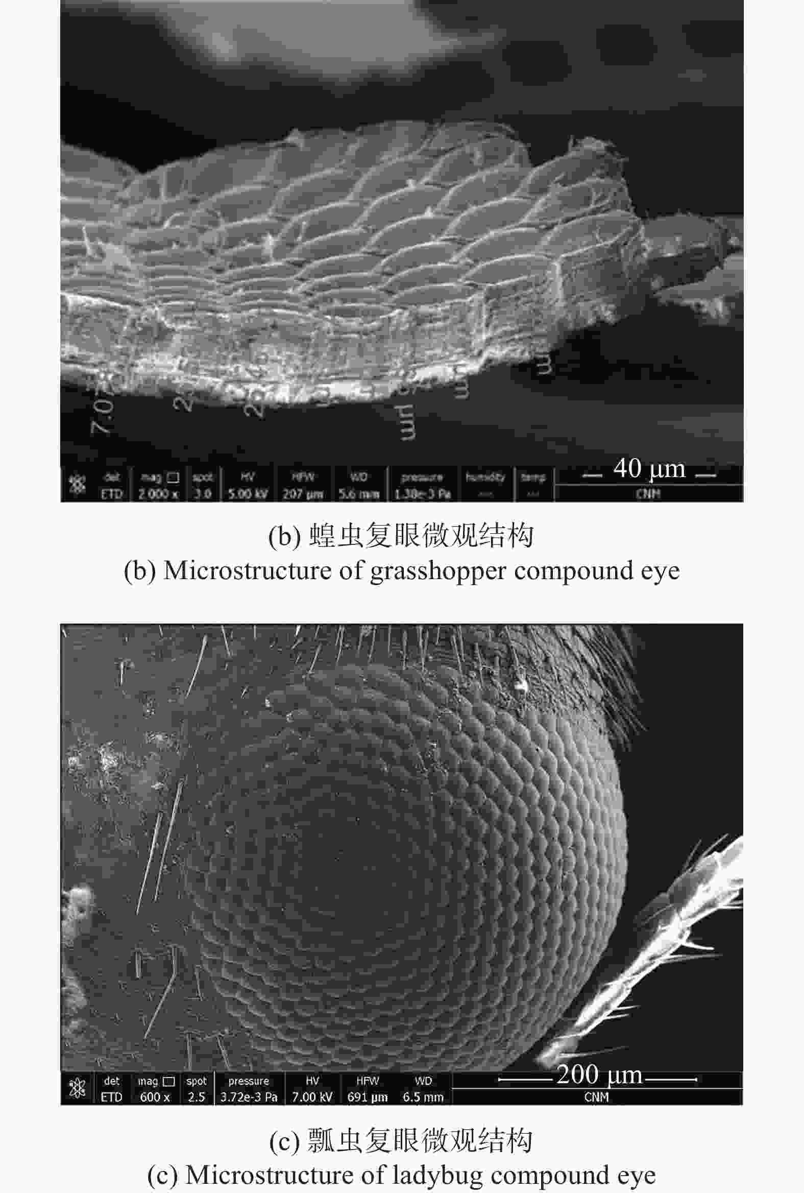
图 1 复眼微观图
Figure 1. Microscopic view of compound eye
-
文中基于该结构类型的复眼,设计了一种六边形子眼紧密拼接形式的曲面微透镜阵列,该结构既能满足复眼对于大视场的需求,又可使整个结构紧凑,提高复眼球壳基底的空间利用率[10]。
在设计子眼透镜时,为了实现物空间的完整成像,相邻子眼间的视场要有一定的重叠比例,保证各个子眼在成像后,像面可以通过后期图像处理算法拼接在一起,组成一个新的完整的像面。同时在保证大视场的前提下,要使得子眼的成像区域不发生重叠,便于后期进行图像处理和图像拼接。综上所述,即要保证其大视场优势,又要有一定重叠比例,所以子眼视场角
$\Delta \theta $ 与子眼间夹角$\Delta \varphi $ 的关系应满足:$\Delta \varphi < $ $ \Delta \theta < 2\Delta \varphi $ 。子眼间夹角与复眼参数的关系为:
$$ \Delta \phi ={\arctan}\frac{2a}{R} $$ (1) 如图2所示,a为子眼的半口径,R为复眼所在的球壳基底的曲率半径。
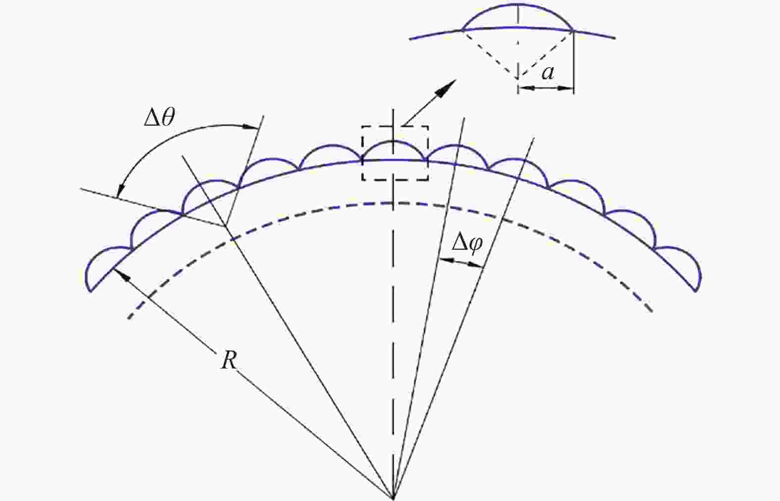
图 2 微透镜阵列结构示意图
Figure 2. Structural schematic diagram of the micro-lens array
根据设计参数的要求,取子眼的半口经a为0.25 mm,复眼的口径D为8.66 mm,微透镜阵列的角度为120°,根据几何关系可知,复眼所在的球壳基底的曲率半径R = 5 mm,由公式得出
$\Delta \varphi \;{\rm{ = 5}}{\rm{.7}}{{\rm{2}}^ \circ }$ ,取子透镜视场角$\Delta \theta = {{\rm{6}}^ \circ }$ 。常见的生物复眼类似于正透镜,设置子眼前后表面的曲率半径为
${r_1} = - {r_2}$ ,${r_1} > 0$ 。为保证复眼结构的小型化,设定子眼焦距${f'}$ 为0.93 mm,子眼厚度d为0.35 mm。子眼透镜的材料选择便于3D打印制造的PMMA光固化材料,其折射率为1.4918,根据公式(2):$${f'} = \frac{{n{r_1}{r_2}}}{{\left( {n - 1} \right)\left[ {n\left( {{r_2} - {r_1}} \right) + \left( {n - 1} \right)d} \right]}}$$ (2) 可得到子眼的曲率半径为
${r_1}$ = 0.97 mm,${r_2}$ = −0.97 mm。将上述计算得到的初始参数值输入ZEMAX软件中进行分析及优化,由于子眼的视场和口径均较小,像差也很小。优化后的子眼结构及成像质量如图3所示。

图 3 子眼的结构图及成像质量图
Figure 3. Structure diagram and image quality diagram of sub-eye
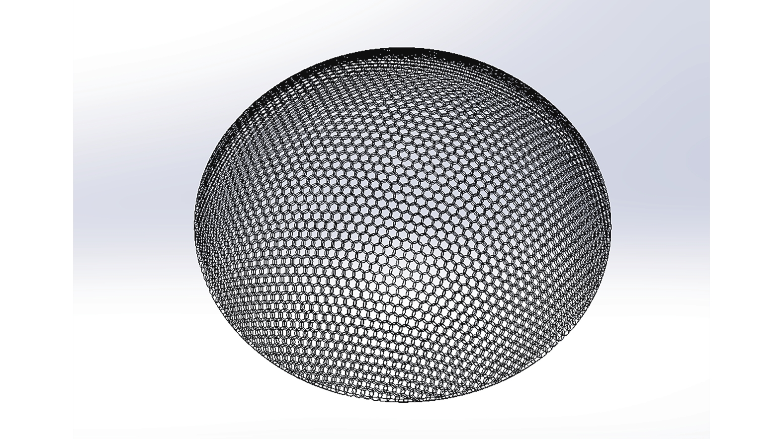
在ZEMAX中的非序列模式对曲面微透镜阵列进行建模,以中心子眼为对称中心,在三维空间内进行环形阵列,得到曲面微透镜阵列模型如图4所示。

图 4 复眼模型
Figure 4. Compound eye model
文中采用六边形子眼紧密拼接的结构形式,为避免相邻子眼之间的串扰现象,设置光阑阵列。光阑阵列位于曲面微透镜阵列和转像系统之间,且微透镜阵列到曲面像间的距离为1.5 mm,即可确定光阑长度近似1.5 mm。考虑3D打印的精度为2 μm,光阑内壁厚度为0.05 mm。光阑孔与子眼一一对应且排列方式相同,由于光阑是有一定斜率的通孔,故将光阑设计为锥形结构。通过ZEMAX软件来确定光阑的参数,每个光阑采用相同的设计参数进行阵列,光阑前端与子透镜后表面相对应,其口径应略小于子眼口径,考虑内壁厚度,故将光阑前端口径设为0.4 mm,光阑后端口径大小应略大于子透镜的像面大小,避免光阑对成像光束的干扰,故将光阑后端口径设为0.25 mm。该结构可作为视场光阑来限制子眼的成像区域,能有效防止子眼间的成像串扰现象,保证不同子眼透镜间的成像独立。
根据上述分析和计算,通过ZEMAX软件对仿生复眼进行模拟,选取曲面复眼的最大视场(60°)进行光线追迹,因复眼结构是对称的,所以列出中心子眼组、过渡子眼组和边缘子眼组,每个子眼设置三个角度(0°、3°、−3°)的入射光线,如图5所示,加入光阑阵列后,每个子眼有着特定的成像通道,相互独立成像,互不干扰。

图 5 光阑阵列结构图
Figure 5. Structure diagram of aperture array
-
复眼系统需要在光阑阵列后添加转像系统,将弯曲的像面转换为平面形式。转像系统的物面范围和半径不能小于微透镜阵列所成像的曲面半径,保证光束经过不同子眼所成的像能够被转像系统全部接收[11]。转像系统位于微透镜阵列和接收系统之间,曲面微透镜阵列所成的曲面像即作为转像系统的物面,该面曲率半径为3 mm。
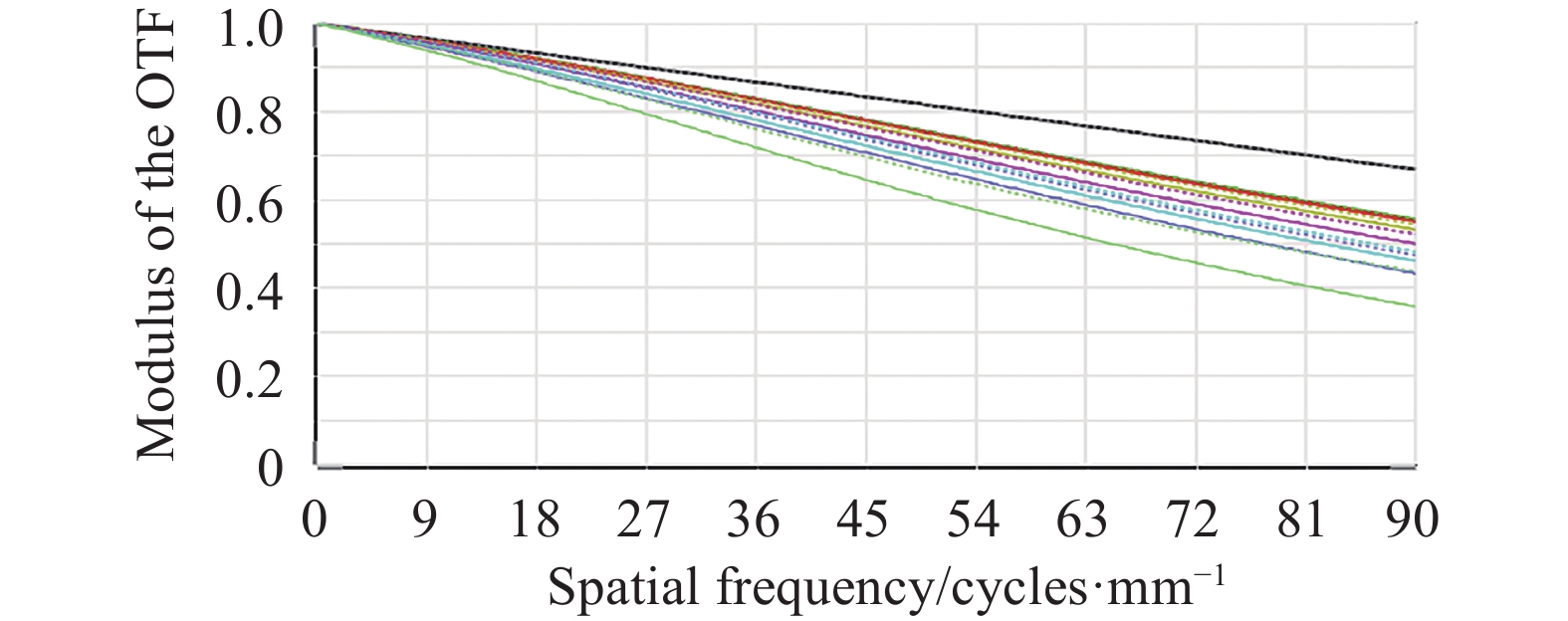
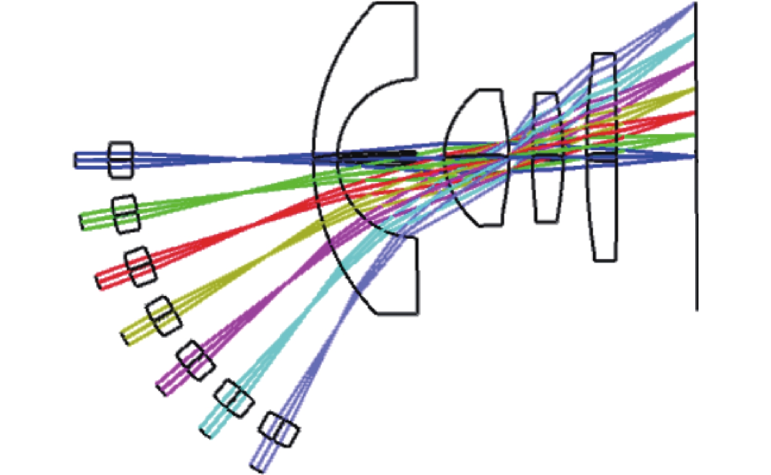
选用ZEBASE中的一款具有大视场的光学系统作为转像系统的初始结构。该系统由八种材料组成,总长度为15.29 mm,焦距为1.23 mm,视场角为180°,结构如图6所示。虽然该结构有着较大的视场,但其筒长过大,透镜材料不适用于3D打印,且从图7中MTF曲线形态来看,该系统初始结构的成像质量并不理想,许多光学参数也均未满足项目指标要求。因此需要对该初始结构进行进一步优化。
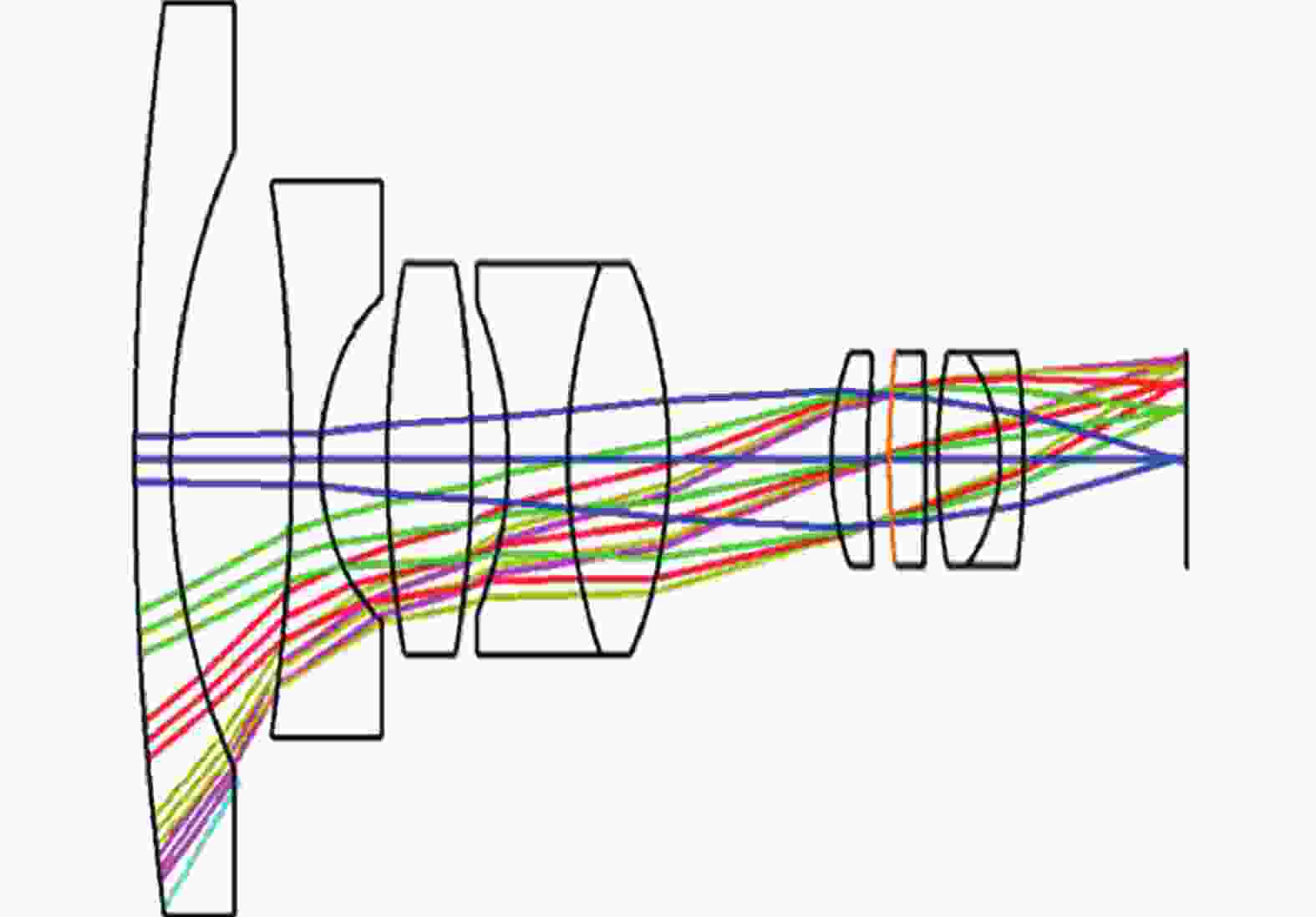
图 6 初始结构光路图
Figure 6. Light path diagram of initial structure
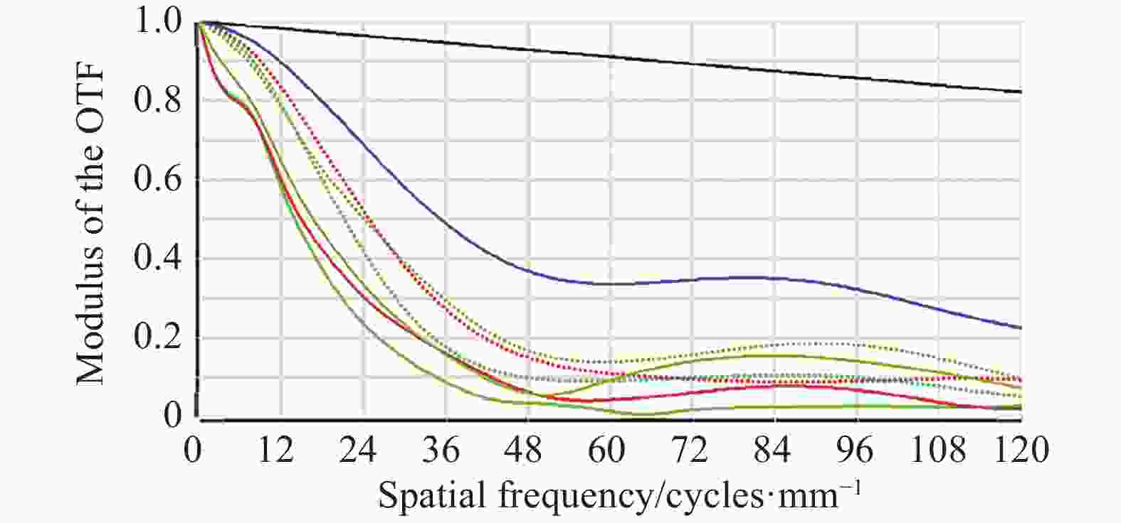
图 7 初始结构的MTF曲线图
Figure 7. MTF curve diagram of initial structure
该系统结构由3D打印技术进行制造,初始结构材料均是玻璃,无法作为3D打印的材料,为满足3D打印加工要求,需要对系统的材料进行替换。首先,将材料的折射率和阿贝数设为变量并优化至1.492和57.44,将材料替换为PMMA。其次,根据相应的设计指标要求,该初始结构长度偏大,将其缩小至原来的二分之一。由于转像系统的物面也是微透镜阵列的像面,应将初始结构的物面(无穷远)逐步优化至合理位置,并将其半径优化为3 mm。在合理控制系统筒长的基础上,将物距优化为 1.2 mm,系统焦距为1.44 mm。在优化过程中,观察该系统各个透镜的光焦度,将光焦度小、对光线偏折能力差的透镜进行合并或删除。将元件数量减少到四片,使结构更加紧凑,便于小型化、轻量化。最后,合理设置光阑位置,优化系统的整体结构,使其达到成像质量的要求。
系统像面由型号为Sony ICX-618ALA的四分之一CCD接收,该类型的CCD感光表面对角线的长度为4.5 mm,像素尺寸大小为5.6 μm×5.6 μm。根据奈奎斯特采样法计算出截止频率为89.3 lp/mm。
优化后的转像系统成像光路如图8所示,转像系统由四片透镜组成,共轭距离为6.5 mm。

图 8 转像系统光路图
Figure 8. Light path diagram of the relay system
对于成像光学系统来说,光学传递函数能够客观且全面地反映出系统的成像质量[12],如图9所示,在90 lp/mm,各视场的MTF曲线值均大于0.35,且曲线呈平滑趋势,满足该系统成像要求。
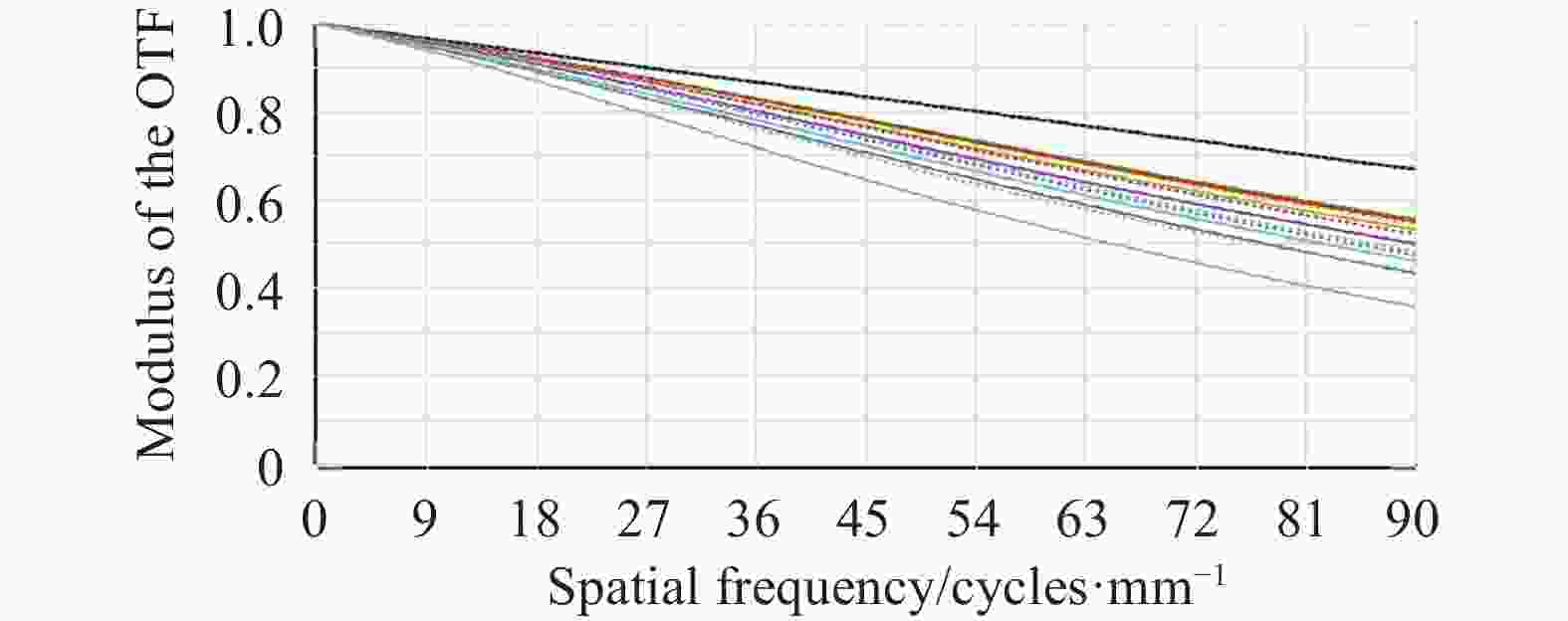
图 9 转换系统的MTF曲线图
Figure 9. MTF diagram of the conversion system
点列图中的点密集程度可以对光学系统的成像质量进行评估,同时也是常用像质评价方法之一[13]。如图10所示,各视场的RMS均方根半径均小于艾里斑半径,满足成像质量要求。

图 10 转换系统的点列图
Figure 10. Spot diagram of the conversion system
-
复眼系统由微透镜阵列、光阑阵列、转像系统组成。根据光学系统的光瞳衔接准则,微透镜阵列的出瞳位置应与转像系统的入瞳位置相重合,将光阑设置在转像系统第二片透镜的后表面上,系统组合完成后 其成像质量并不理想。考虑到子眼透镜口径和视场都很小,对像差的影响也很小,综合分析影响组合系统成像质量的最大因素是转像系统,通过系统优化来平衡光阑移动给系统带来的像差影响。
优化完成后的组合复眼光路如图11所示,利用多重结构给出七个视场(0°、10.5°、21°、30°、40.3°、50°、60°)的光路图,整个系统长度为8.7987 mm。

图 11 组合复眼系统的光路图
Figure 11. Light path diagram of the combined eye optical system
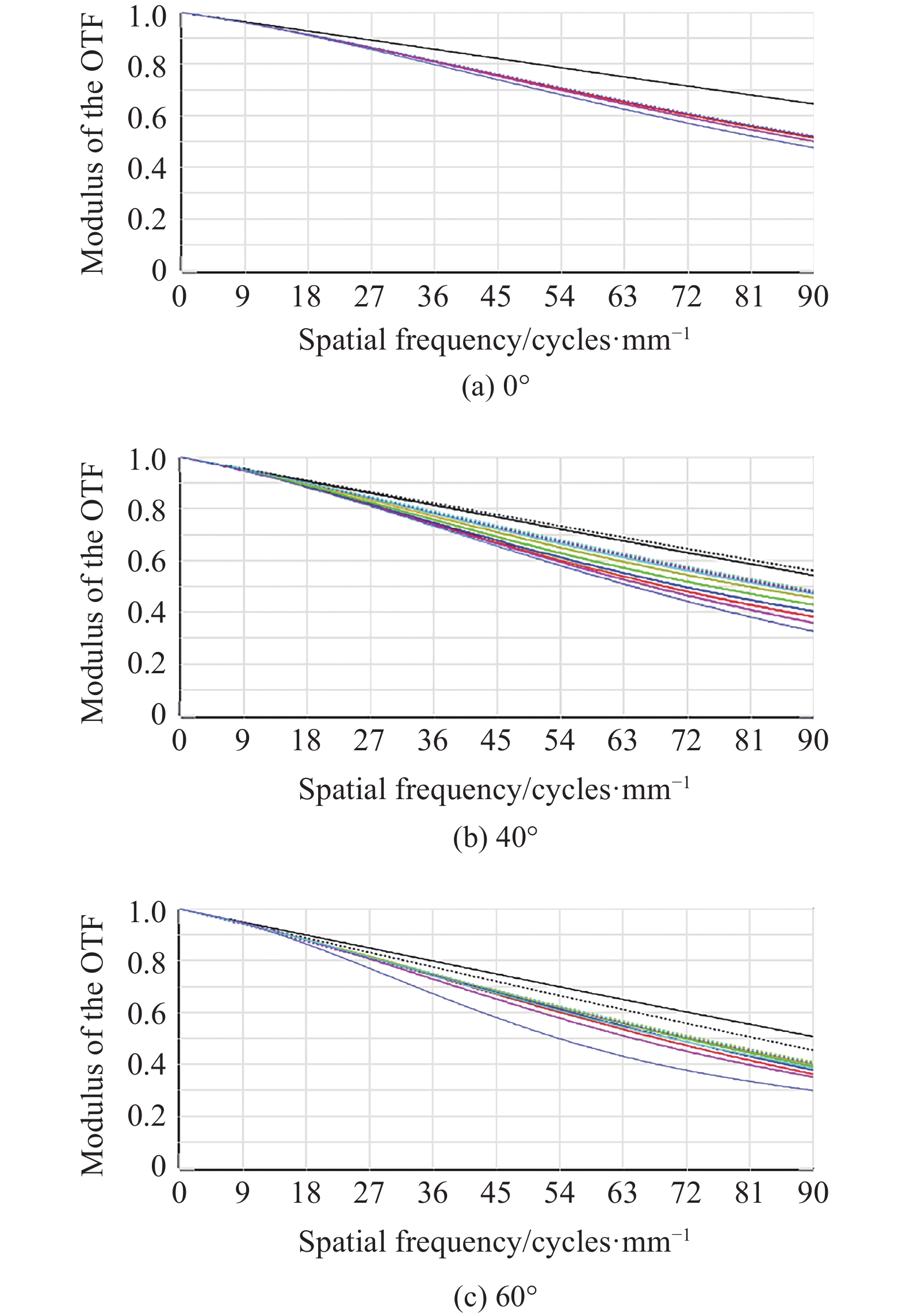
由于篇幅限制,文中仅给出三个视场下(0°、40°、60°)的MTF曲线图,如图12所示,在90 lp/mm处,三个视场的MTF分别大于0.45、0.32、0.3,该系统已达到成像质量要求。
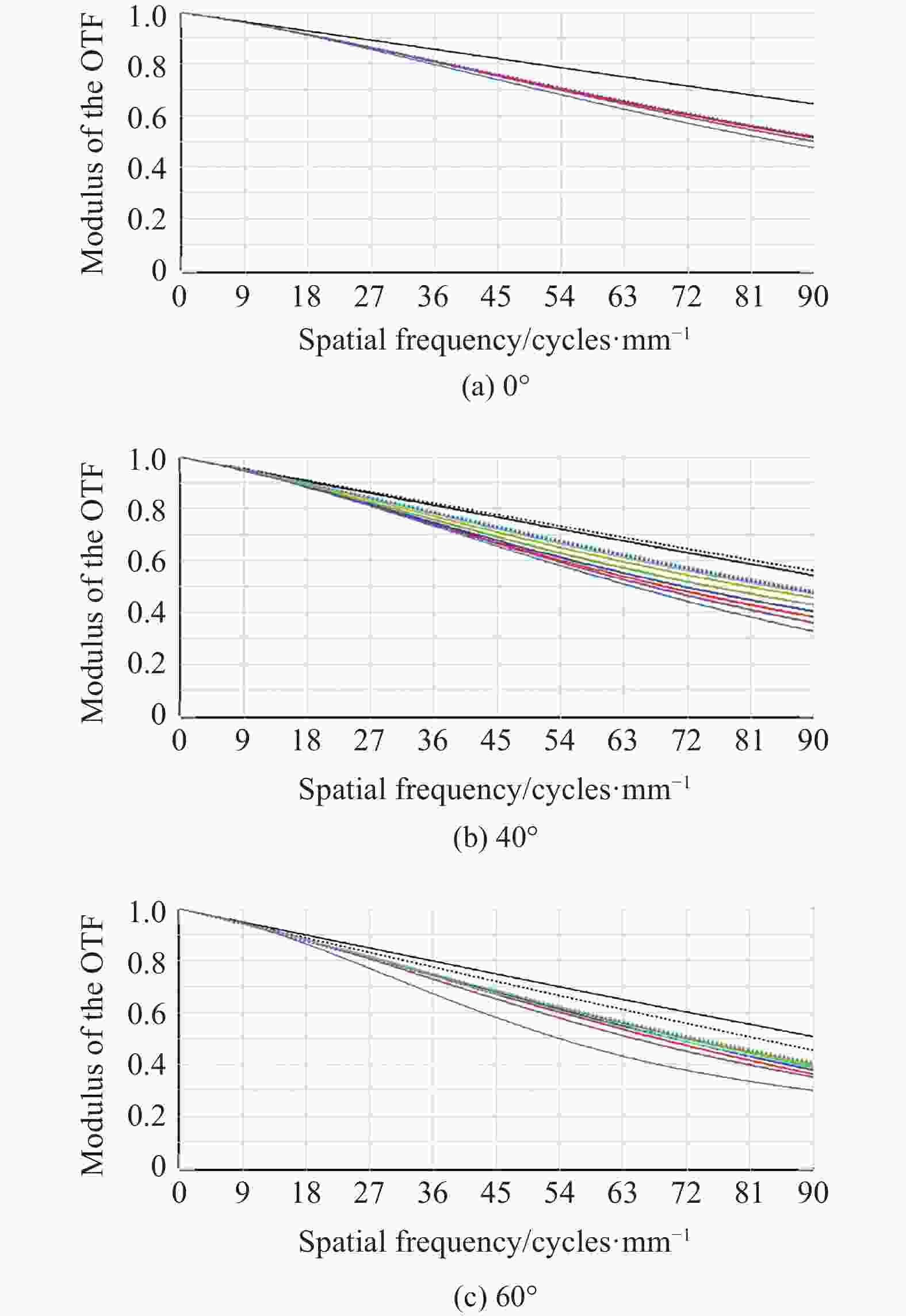
图 12 复眼系统不同视场的MTF曲线
Figure 12. MTF curves of compound eye system at different FOVs
三个视场(0°、40°、60°)的点列图如表1所示,各个视场的RMS半径小于艾里斑半径,且在探测器的像元尺寸范围内(5.6 μm)满足该系统的成像质量要求,且无明显色差。
表 1 不同视场的点列图
Table 1. Spot diagrams of different fields of view
Angle 0° 40° 60° 0° 


RMS radius 2.283 μm 2.701 μm 2.939 μm 3° 


RMS radius 2.547 μm 2.678 μm 2.632 μm −3° 


RMS radius 2.541 μm 3.172 μm 4.156 μm Airy radius 4.365 μm 4.732 μm 5.034 μm 复眼系统由S130型的3D打印设备进行制作,在透镜间设计柱状支撑结构,用于固定透镜位置,同时在打印过程中柱状结构有利于打印液的流出,从而确保打印精度。为了避免杂散光对复眼成像的影响,复眼结构的外壳均为遮光材料,“镜筒”、光阑由黑色树脂材料整体打印。以转像系统的光阑为分界,前后两部分分别进行打印,镜片和镜筒之间通过垫片和压圈固定。光阑阵列由黑色树脂材料单独打印,以柱状结构为支撑,装配在复眼球壳后部,复眼球壳及前后部分均以卡扣的形式安装在系统两侧。仿生复眼系统的结构图,如图13所示。
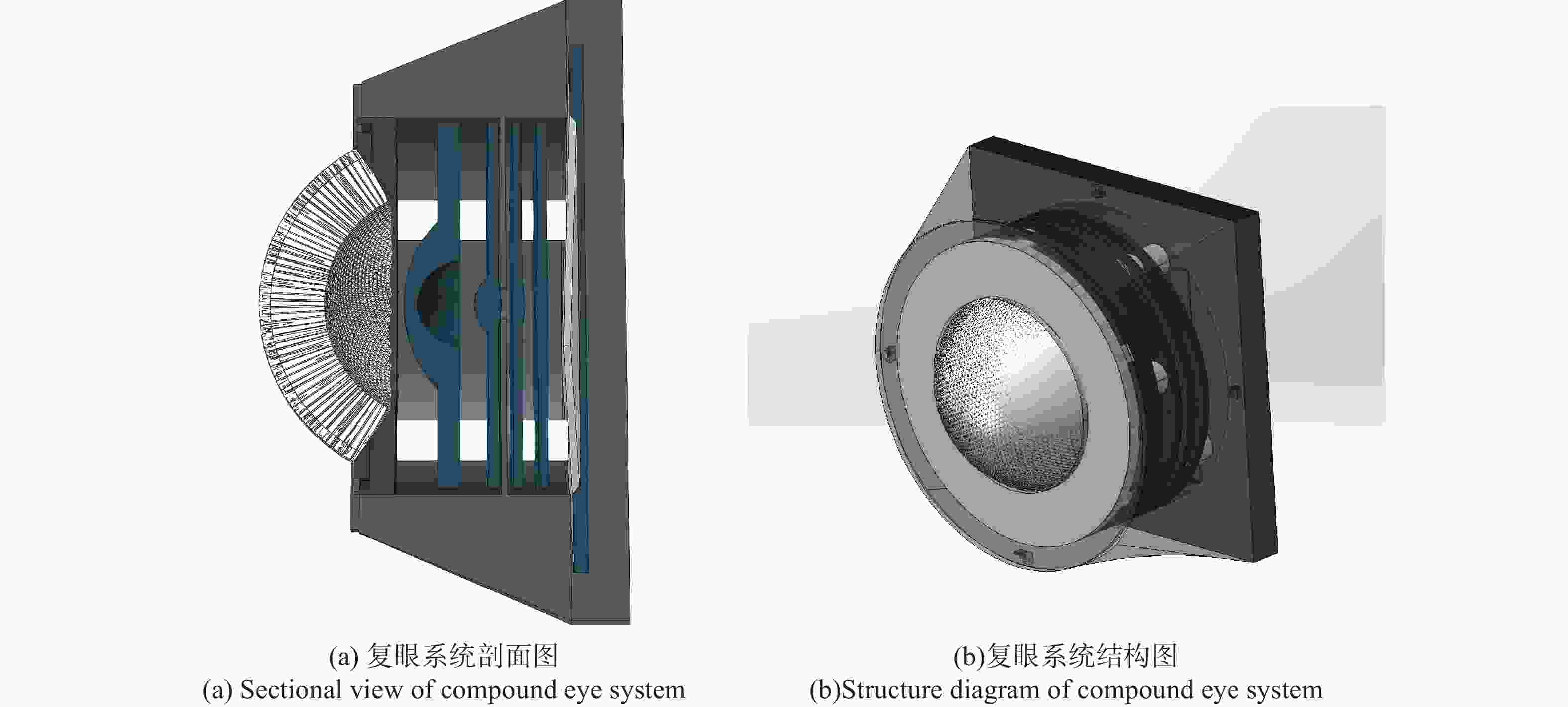
图 13 复眼系统模型
Figure 13. Model of compound eye system
文中对仿生复眼系统进行了公差分析,保证复眼系统加工的可行性。3D激光打印机的最高打印精度为2 μm,各公差参数设置范围如表2所示。选择“ MTF平均值”模式作为公差分析的评价方法,采用灵敏度法和蒙特卡洛法对1000组镜头数据进行公差分析,分析结果如表3所示。
表 2 公差参数范围
Table 2. Tolerance parameter range
Sort Data Radius/mm 0.002 Thickness/mm 0.002 Surface decenter/mm 0.002 Surface tilt 0.03° Element decenter 0.01 Element tilt 0.03 Abbe 0.5% Index 0.001 表 3 复眼系统公差分析结果
Table 3. Tolerance analysis results of compound eye system
Name Result Number of Monte Carlo 1000 MTF nominal value 0.348 542 13 MTF average 0.347 187 12 98% lens MTF value >0.336 334 57 80% lens MTF value >0.343 335 32 50% lens MTF value >0.348 132 40 20% lens MTF value >0.351 250 35 10% lens MTF value >0.352 350 71 2% lens MTF value >0.353 558 39 可以看出,系统MTF的名义值为0.34854213。透镜在98%和10%时的MTF值分别大于0.33633457和0.35235071。从以上数据可以看出,公差分析后MTF值的变化量很小,对仿生复眼系统的公差分析结果比较合理,可以满足系统成像质量的要求。
-
文中设计了一款基于六边形子眼紧密拼接结构的仿生复眼系统,总长度为8.7987 mm,视场为121°,单个子眼透镜的通光口径为500 μm,视场角为6°。曲面微透镜阵列采用正六边形紧密拼接的方式进行排布,提高了球壳基底的空间利用率的同时增大了光能利用率。加入光阑阵列,有效防止子眼间的成像串扰。通过设计转像系统,将曲面微透镜阵列所成的焦曲面像转换为平面像,优化完成后,复眼系统的全视场MTF值均大于0.3,RMS半径均在艾里斑半径内。在公差分析之后,设计的复眼系统满足成像要求。该系统光学性能良好,结构紧凑利于小型化、轻量化,在医疗检测、航空航天、军事方面等领域有着广泛的应用潜力。
Design of bionic compound eye system based on hexagonal closely spliced structure
-
摘要: 基于仿生复眼的视觉优势,分析了仿生复眼的研究进展,对复眼的成像原理及部分昆虫复眼的结构进行了研究。根据生物复眼的结构形态,设计了六边形紧密拼接形式的曲面微透镜阵列及转像系统。同时,为了防止相邻子眼间的成像光束串扰,设计了单个光阑长度为1.5 mm的光阑阵列,实现了各子眼的单通道成像。根据光瞳衔接原则,对微透镜阵列和转换系统进行组合并优化。整个复眼的口径为8.66 mm,视场角为121°,每个子眼的口径为500 μm,子眼视场角为6°,在90 lp/mm处,复眼系统的MTF值均大于0.3,其RMS半径均小于艾里斑半径,系统成像质量达到设计要求。为满足3D增材制造工艺需求,设计了复眼系统的机械结构。公差分析结果表明,3D增材制造工艺可以满足系统的像质要求。Abstract: Based on the visual advantages of bionic compound eyes, the research progress of bionic compound eyes was analyzed, and the imaging principle of compound eyes and the structure of some insect compound eyes were studied. According to the structure of the biological compound eye, a hexagonal closely spliced curved micro-lens array and image transfer system were designed. At the same time, in order to prevent the crosstalk of imaging beams between adjacent sub-eyes, an aperture array with a single aperture of 1.5 mm in length was designed to realize single-channel imaging of each sub-eye. According to the principle of pupil connection, the micro lens array and the conversion system were combined and optimized. The diameter of the entire compound eye was 8.66 mm, the field of view was 121°, the diameter of each sub-eye was 500 μm, and the field of view of the sub-eye was 6°. At 90 lp/mm, the MTF value of the compound eye system was greater than 0.3, and the RMS spot radius were less than the radius of the Airy disk, the imaging quality of the system meet the requirements of the design index. In order to met the requirements of 3D additive manufacturing process, the mechanical structure of the compound eye system was designed. The tolerance analysis result shows that the system structure meets the preparation requirements of 3D printing technology.
-
表 1 不同视场的点列图
Table 1. Spot diagrams of different fields of view
Angle 0° 40° 60° 0° RMS radius 2.283 μm 2.701 μm 2.939 μm 3° RMS radius 2.547 μm 2.678 μm 2.632 μm −3° RMS radius 2.541 μm 3.172 μm 4.156 μm Airy radius 4.365 μm 4.732 μm 5.034 μm  下载: 导出CSV
表 2 公差参数范围
Table 2. Tolerance parameter range
Sort Data Radius/mm 0.002 Thickness/mm 0.002 Surface decenter/mm 0.002 Surface tilt 0.03° Element decenter 0.01 Element tilt 0.03 Abbe 0.5% Index 0.001
下载: 导出CSV
表 3 复眼系统公差分析结果
Table 3. Tolerance analysis results of compound eye system
Name Result Number of Monte Carlo 1000 MTF nominal value 0.348 542 13 MTF average 0.347 187 12 98% lens MTF value >0.336 334 57 80% lens MTF value >0.343 335 32 50% lens MTF value >0.348 132 40 20% lens MTF value >0.351 250 35 10% lens MTF value >0.352 350 71 2% lens MTF value >0.353 558 39
下载: 导出CSV
-
[1] Zhang Hongxin, Lu Zhenwu, Wang Ruiting, et al. Study on curved compound eye imaging system [J]. Optics and Precision Engineering, 2006, 14(3): 346-350. (in Chinese) doi: 10.3321/j.issn:1004-924X.2006.03.002 [2] Lei Weining, Guo Yunzhi, Gao Tingting. Study on the structure of large field view detection system based on bionic compound eye [J]. Optics & Optoelectronic Technology, 2016, 14(3): 62-66. (in Chinese) [3] Tian Yuqi, Gao Tianyuan, Zhao Yu, et al. Angle error of bionic compound eye imaging system [J]. Infrared and Laser Engineering, 2018, 47(3): 0310001. (in Chinese) [4] Tan Xuechun, Wu Zhichao, Liang Zhu. Design and experiment of artificial compound eye receiving system [J]. Optics and Precision Engineering, 2011, 19(5): 992-997. (in Chinese) doi: 10.3788/OPE.20111905.0992 [5] 邹成刚. 仿生复眼的光学设计与模拟仿真[D]. 天津大学, 2013. Zou Chenggang. Optical design and simulation of the artificial compound eyes [D]. Tianjin: Tianjin University, 2013. (in Chinese) [6] Cao Axiu, Pang Hui, Zhang Man. et al. Design and fabrication of an artificial compound eye for multi-Spectral imaging [J]. Micromachines, 2019, 10(3): 208-218. doi: 10.3390/mi10030208 [7] Thiele S, Araenbacher K, Gissibl T, et al. 3D-printed eagle eye: Compound micro lens system for foveated imaging [J]. Science Advances, 2017, 3(2): e1602655. doi: 10.1126/sciadv.1602655 [8] Floreano Dario, Pericet-Camara Ramon, Viollet Stéphane, et al. Miniature curved artificial compound eyes [J]. Proceedings of the National Academy of Sciences of the United States of America, 2013, 110(23): 9267-9272. [9] Li Zhengwen, Wang Yu, Xiao Jianliang. Mechanics of bioinspired imaging systems [J]. Theoretical & Applied Mechanics Letters, 2016, 6(1): 11-20. [10] Hu Xulei, Gao Ming, Chen Yang. Design of curved bionic compound eye optical system with large field of view [J]. Infrared and Laser Engineering, 2020, 49(1): 0114002. (in Chinese) [11] Cao Zhaolou, Zhan Zhenxian, Wang Keyi. Structural design of spherical compound eye lens for moving object detection [J]. Infrared and Laser Engineering, 2011, 40(1): 70-73. (in Chinese) doi: 10.3969/j.issn.1007-2276.2011.01.015 [12] Fu Yuegang, Zhao Yu, Liu Zhiying, et al. Design of compact bionic compound eye optical system used for target identification [J]. Infrared and Laser Engineering, 2017, 46(6): 0602001. (in Chinese) [13] Cheng Hongtao, Wu Yuchong, Lu Jie, et al. Design of hyper-field zoom bionic eye optical system [J]. Infrared and Laser Engineering, 2016, 45(8): 0818004. (in Chinese) -

 点击查看大图

图(14) / 表(3)
计量
- 文章访问数: 666
- HTML全文浏览量: 236
- PDF下载量: 60
- 被引次数: 0


