


 下载:
下载:

-
运动物体的三维重构是线上产品检测等应用的基础。相移法(Phase Shifting Profilometry-PSP)因其精度高、速度快、鲁棒性强等优点,是目前最流行的三维重构技术之一。相移法测量系统通常包括一个相机和一个投影仪。投影仪从一个角度投射多幅(通常至少3幅)相移量已知的正弦波条纹图案到物体表面,由相机从另一个角度对条纹图案进行拍摄。通过对条纹图进行分析后提取正弦波条纹的相位值,最终利用相位信息进行物体三维重构。由于重构过程需要多幅条纹图,因此要求物体在条纹图拍摄过程中保持静止。物体运动不仅会导致多幅条纹图中的物体位置不匹配,还会改变物体同一点上条纹图之间的相移量。因此,传统的相移法算法在重构运动物体时会产生较大误差。
近年来,运动物体的三维重构受到了广泛关注。Shijie Feng等[1]提出了一种刚性物体运动误差补偿方法。通过分析由运动引起的测量误差机理,补偿了由物体运动引起的重构误差。然而该方法对于物体表面各个点的运动误差为常量时有效,无法解决物体表面不同点包含不同运动误差的情况。Ziping Liu等[2]通过对条纹图之间的物体运动进行估计,提出了一种基于迭代运算的运动物体测量方法。但该方法假设物体在多幅条纹图之间为匀速运动。Yajun Wang等[3]基于希尔伯特变换对运动引起的误差进行补偿。通过分析发现运动引起的波浪误差频率为投射条纹频率的两倍。通过希尔伯特变换将条纹图移动半个周期并提取相位,利用此相位信息补偿原始条纹图提取的相位值,进而减少由运动引起的相位误差。该方法对于表面高度缓慢变化物体效果较好。Xinran Liu[4]等提出使用一种计算运动后相移量的新方法,进而对运动误差进行补偿。该方法要求物体在多幅条纹图间进行匀速运动或加速度为常量的运动。Qian Jiaming[5]等提出了一种混合傅里叶变换相移轮廓术的新方法,实现了静态和动态场景下的三维重构。PSP应用于静态区域,FTP(Fourier transform profilometry)用于补偿运动对PSP引入的误差。该算法需要FTP和PSP。笔者课题组利用物体的运动信息进行三维重构,通过将运动信息引入到重构模型中,消除运动引起的误差,实现运动物体三维重构[6-10]。参考文献[6]首先实现了仅包含二维运动物体时的三维重构。通过预先放置在物体表面的标记点来跟踪物体的运动并计算描述物体运动的旋转平移矩阵;结合物体运动对相位信息的影响,提出了一种新的包含运动信息的三维重构模型,通过对新模型方程组进行求解,可以得到运动物体的正确的相位信息。由于需要预先在物体表面放置标记点,无法实现自动三维重构,因此参考文献[8]采用SIFT(Scale-invariant feature transform)算法来跟踪物体运动,达到自动跟踪、重构运动物体的目的。参考文献[7]采用迭代最小二乘法实现了对三维运动物体进行了重构。以上方法仅可重构单一的、高度缓慢变化的物体,参考文献[10]针对同一场景下的多个运动物体进行了重构,且被测物体高度可不连续变化。但此方法要求多个被测物体必须具有相同的运动轨迹。当多个运动物体具有不同的运动轨迹时则重构失败。
文中提出了一种新的多运动物体重构算法。多个被测物体之间可具有不同的二维运动。首先,对多个被测物体进行识别并确定相应的目标区域;然后基于目标区域分别对不同的被测物体进行跟踪,并得到描述不同物体运动的旋转平移矩阵。最后,基于包含运动信息的三维重构模型,逐一对被测物体进行重构。
-
对于N步相移法,相机拍摄到参考平面上的条纹图可以表示为:
$$I_n^p(x,y) = A + B\cos ({\phi ^p}(x,y) + \frac{{2\pi (n - 1)}}{N})$$ (1) 式中:p代表参考平面;
$n = 1,2,3, \cdots ...,N$ ;$I_n^p(x,y)$ 为条纹图的强度分布;A表示环境光强;B为正弦条纹图的振幅;${\phi ^p}(x,y)$ 为参考平面的相位分布。同理,物体表面的条纹图可以表示为:
$$I_n^w\left( {x,\left. y \right)} \right. = A + B\cos ({\phi ^w}\left( {\left. {x,y} \right)} \right. + \frac{{2\pi \left( {{{n - 1}}} \right)}}{{{N}}})$$ (2) 式中:
$w$ 代表物体表面;${\phi ^w}\left( {\left. {x,y} \right)} \right.$ 为物体表面的相位分布。相位分布
${\phi ^p}(x,y)$ 和${\phi ^w}\left( {\left. {x,y} \right)} \right.$ 可以分别通过如下公式计算获得:$${\phi ^p}(x,y) = \arctan \frac{{ - \sum\limits_{n = 1}^N {I_n^p(x,y)\sin 2\pi (n - 1)/N} }}{{\sum\limits_{n = 1}^N {I_n^p(x,y)\cos 2\pi (n - 1)/N} }}$$ (3) $${\phi ^w}(x,y) = \arctan \frac{{ - \sum\limits_{n = 1}^N {I_n^w(x,y)\sin 2\pi (n - 1)/N} }}{{\sum\limits_{n = 1}^N {I_n^w(x,y)\cos 2\pi (n - 1)/N} }}$$ (4) 由公式(3)和(4)可知,相位分布
${\phi ^p}(x,y)$ 和${\phi ^w}\left( {\left. {x,y} \right)} \right.$ 为包裹在$( - \pi ,\pi ]$ 范围内的周期性数值,相位解包裹可将不连续的相位分布变换为单调的连续相位,进而可得到物体相位与参考平面相位之间的相位差:$$\varPhi (x,y) = {\varPhi ^w}(x,y) - {\varPhi ^p}(x,y)$$ (5) 式中:
$\varPhi (x,y)$ 表示由于物体高度引起的相位差;${\varPhi ^w}(x,y)$ 和${\varPhi ^p}(x,y)$ 分别为物体和参考平面的解包裹相位,根据$\Phi (x,y)$ 可获得物体表面的三维信息。从公式(4)可以看出,此过程要求物体在不同条纹图之间保持静止。一旦物体发生运动,则不仅导致条纹图中物体的位置不匹配,还破坏了条纹图中设定的相移量,造成较大的重构误差。
-
当被测物体为多个独立运动物体时,首先需要确定被测物体的数量及位置,然后依次跟踪物体的运动,并分别计算描述物体运动的旋转平移矩阵。最后针对不同物体分别进行三维重构。具体实现过程如下:
多目标运动物体的三维重构,要求对多个物体分别进行运动跟踪。条纹信息是三维重构的重要因素但不利于对物体的识别和跟踪。物体的识别和跟踪要求清晰的物体图像信息,物体上的条纹则会影响识别效果。为了既获得物体的条纹信息,又采集到清晰的物体图像,文中利用彩色相机多通道手段来分离条纹和物体图像。投影仪投射红色条纹到物体表面,彩色相机拍摄反射回来的条纹图。在彩色条纹图中,红色通道中为包含相位信息的条纹图;蓝色通道中可以得到没有条纹的纯物体图像,纯物体图像可用来进行物体的识别和跟踪。需要注意的是,蓝色通道中的物体图像亮度取决于周围环境光的强弱,如果环境光强度较低,则蓝色通道中的物体图像较暗,成像较差,不利于后续的识别和跟踪。此时需在投射红色条纹时增加一定强度的蓝色背景光或白光。获得清晰的物体图像后,需要确定物体的数量及位置。文中通过手动方法在重构计算之前在图像中设置;
设置物体所在的区域后,采用高速跟踪算法KCF(Kernelized Correlation Filters)逐个跟踪目标区域内的物体[11]。KCF算法可有效确定物体运动后所在的区域范围,但不能获得物体的运动方向和旋转角度等信息。因此,文中采用了SIFT算法在物体运动前后区域内进行特征点匹配,获得特征点的对应关系。然后再利用特征点可以通过奇异值分解(Singular value decomposition-SVD)算法计算出描述物体运动的旋转平移矩阵[8]。重复执行以上步骤,获得不同物体对应的旋转平移矩阵。
在获得物体运动的数学描述后,根据运动对相位造成的影响,得到包含运动信息的三维重构模型。最终使用最小二乘算法提取正确的相位信息。详情可以参考文献[8]。假设场景中有三个被测物体,不同物体目标区域内的条纹图可表示为:
$$\begin{split} & I_n^{w1}\left( x, y \right) = A + \\ & B\cos \left({\phi ^p}(f_n^1(x,y),g_n^1(x,y)) + \varPhi \left( {x,y} \right) + \frac{{2\pi \left( {{{n - 1}}} \right)}}{{{N}}}\right)\end{split}$$ (6) $$\begin{split} & I_n^{w2}(x,y) = A + \\ & B\cos \left({\phi ^p}(f_n^2(x,y),g_n^2(x,y)) + \varPhi \left( {x,y} \right) + \frac{{2\pi \left( {{{n - 1}}} \right)}}{{{N}}}\right) \end{split}$$ (7) $$\begin{split} & I_n^{w3}(x,y) = A + \\ & B\cos \left({\phi ^p}(f_n^3(x,y),g_n^3(x,y)) + \varPhi \left( {x,y} \right) + \frac{{2\pi \left( {{{n - 1}}} \right)}}{{{N}}}\right) \end{split}$$ (8) 式中:
$I_n^{w1}$ 、$I_n^{w2}$ 和$I_n^{w3}$ 依次表示三个物体目标区域内的条纹图;$f_n^1( \cdot ),g_n^1( \cdot )$ 、$f_n^2( \cdot ),g_n^2( \cdot )$ 和$f_n^3( \cdot ),g_n^3( \cdot )$ 分别为三个物体对应的运动描述;${\phi ^p}$ 可以通过参考平面上的条纹图获得。以描述第一个被测物体的公式(6)为例的求解过程,其中
$I_n^{w1}(x,y)$ 和${\phi ^p}(f_n^1(x,y),g_n^1(x,y))$ 是已知参数,$A$ 、$B$ 和$\varPhi (x,y)$ 是未知参数。因此,当${{N}} \geqslant {{3}}$ 时,公式(6)可写为:$$I_n^{w1}(x,y) = A + C(x,y)\cos \delta + D(x,y)\sin \delta $$ (9) 式中:
$C(x,y) = B\cos \varPhi (x,y)$ ;$D(x,y) = - B\sin \varPhi (x,y)$ ,$\delta = $ ${\phi ^p}(f_n^1(x,y),g_n^1(x,y)) + \dfrac{{2\pi \left( {{{n - 1}}} \right)}}{{{N}}}$ 。假设拍摄到的条纹图为$\tilde I_n^{w1}(x,y)$ ,则每个像素的误差平方和为:$$S(x,y) = {\sum\limits_{n = 1}^{{N}} {\left[ {I_n^{w1}(x,y) - \tilde I_n^{w1}(x,y)} \right]} ^2}$$ (10) 基于最小二乘法,当公式(10)最小时,可得:
$$Z(x,y) = {U^{ - 1}}(x,y)V(x,y)$$ (11) 其中
$$U(x,y) = \left[ {\begin{array}{*{20}{c}} N&{\sum\limits_{n = 1}^N {\cos \delta } }&{\sum\limits_{n = 1}^N {\sin \delta } } \\ {\sum\limits_{n = 1}^N {\cos \delta } }&{\sum\limits_{n = 1}^N {{{\cos }^2}\delta } }&{\frac{1}{2}\sum\limits_{n = 1}^N {\sin 2\delta } } \\ {\sum\limits_{n = 1}^N {\sin \delta } }&{\frac{1}{2}\sum\limits_{n = 1}^N {\sin 2\delta } }&{\sum\limits_{n = 1}^N {{{\sin }^2}\delta } } \end{array}} \right]$$ (12) $$Z(x,y) =\left[\begin{array}{*{20}{c}} A &{C(x,y)} &{D(x,y)} \end{array}\right]^{\rm{T}}$$ (13) $$V(x,y) = \left[\!\!\!\!\begin{array}{*{20}{c}} {\sum\limits_{n = 1}^{N} {\tilde I_n^{w1}(x,y)} }\!&\!{\sum\limits_{n = 1}^{N} {\tilde I_n^{w1}(x,y)\cos \delta } }\!&\!{\sum\limits_{n = 1}^{N} {\tilde I_n^{w1}(x,y)\sin \delta } } \end{array}\!\!\!\! \right]^{\rm{T}}$$ (14) 未知参数
$A$ ,$C(x,y)$ 和$D(x,y)$ 可通过公式(11)~(14)得到。相位差$\varPhi \left( {x,y} \right)$ 可以由以下公式得到:$$\varPhi (x,y) = {\rm{arctan}}[ - D(x,y)/C(x,y)]$$ (15) 同理,可以求出
$I_n^{w2}\left( {x,\left. y \right)} \right.$ 和$I_n^{w3}\left( {x,\left. y \right)} \right.$ 对应物体的相位信息。综上所述,以上过程可以总结为以下步骤:
(1)投影红色条纹到物体表面并用彩色相机拍摄;
(2)手动设置多个被测物体的目标区域;
(3)以物体的目标区域内图像为模板,采用KCF算法对物体进行识别和跟踪,并得到运动后条纹图中的被测物体新的目标区域;
(4)通过SIFT算法得到运动前后物体目标区域内的特征点及其对应关系,并计算描述物体运动的旋转平移矩阵;
(5)通过公式(15)计算被测物体的相位信息;
(6)对所有被测物体依次进行(2)~(5),得到所有物体的相位信息;
(7)分别重构所有物体的三维形貌。
-
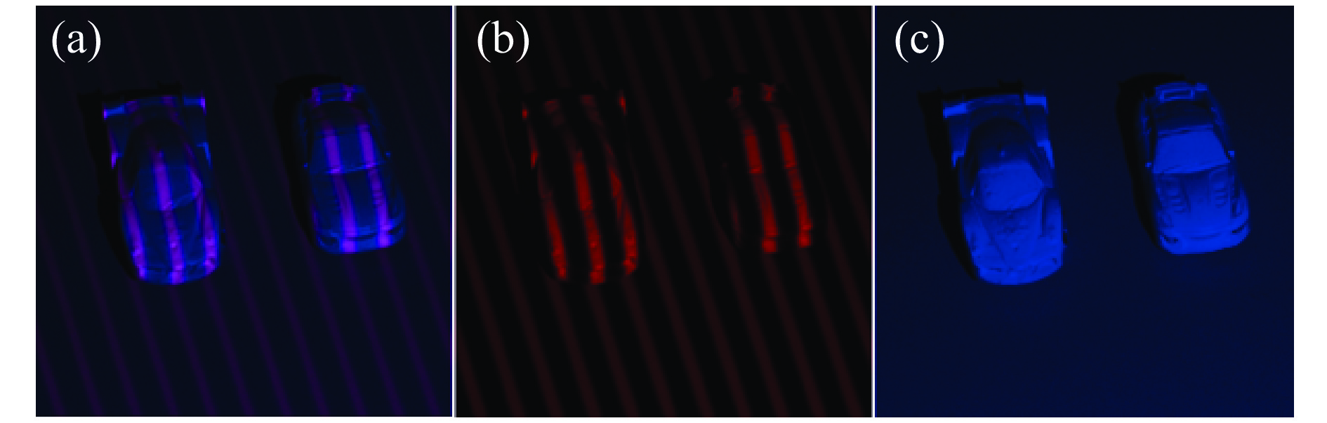
文中实验中采用了彩色摄像机(Allied Vision Manta 504C,分辨率2 452 ×2 056)和投影仪(Wintech DLP PRO 4500,分辨率912 ×1 140)以及两个汽车模型(如图1所示)来验证所提出方法的性能。首先,投影带有蓝色背景光的红色条纹至汽车模型上,并在小车不断发生运动的情况下拍摄条纹图。文中采用三步相移法进行重构,捕获条纹图如图1所示。
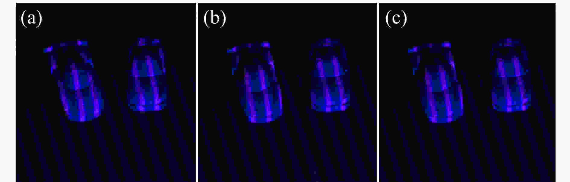
图 1 捕获到的条纹图。(a)~(c)三步PSP捕捉到的运动物体条纹图案
Figure 1. Captured fringe pattern. (a)-(c) The fringe pattern of the moving object captured by the three-step PSP
提取捕获条纹图的红色通道,得到条纹图;提取捕获条纹图的蓝色通道,得到无条纹的纯物体图像,分别如图2(b)~(c)所示。其中红色通道图像包含了相位信息,而蓝色通道图可用于被测物体的识别和跟踪。

图 2 不同通道中的图像。(a)拍摄的物体图像;(b)图2(a)的红色通道图像;(c)图2(a)的蓝色通道图像
Figure 2. Images in different channels. (a) Captured object image; (b) Red channel image of Fig. 2 (a); and (c) the blue channel image of Fig. 2 (a)
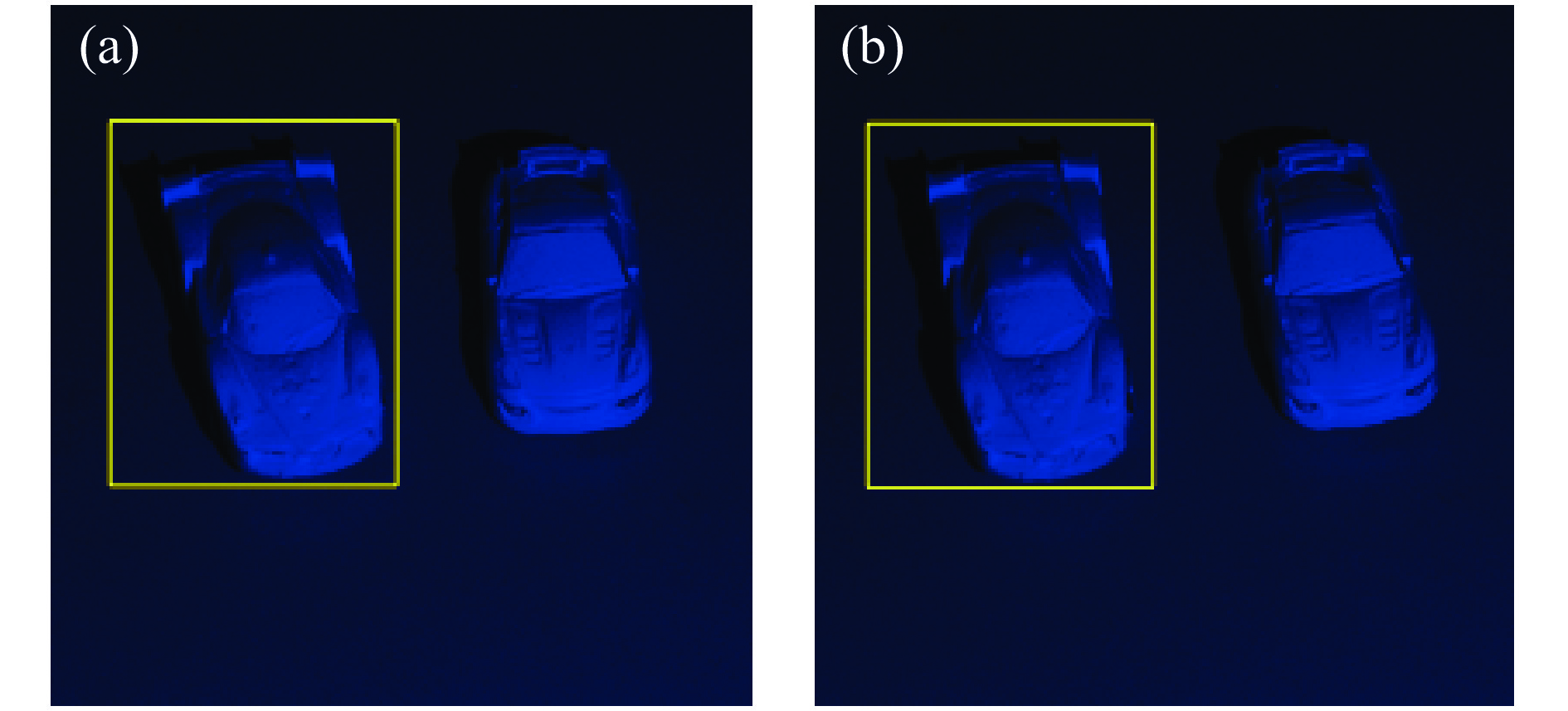
在蓝色通道图像中手动设置被测物体的目标区域(见图3),然后通过KCF算法跟踪框内物体运动,得到运动后的蓝色通道图像中被测物体新的目标区域,新目标区域可用于在下一帧图像中跟踪物体运动,直至完成后续所有运动的跟踪。

图 3 物体定位与跟踪。(a)测量前手动标出的物体目标区域;(b)连续图像中KCF的物体跟踪结果
Figure 3. Targeting and tracking. (a) Identified area of object before movement; (b) Tracking result by KCF
采用SIFT算法得到物体上的特征点及其对应关系(见图4)。对于不同的目标物体,选取其目标区域内至少三组特征点,使用SVD算法计算描述物体运动的旋转平移矩阵,直至获得所有物体运动的数学描述。
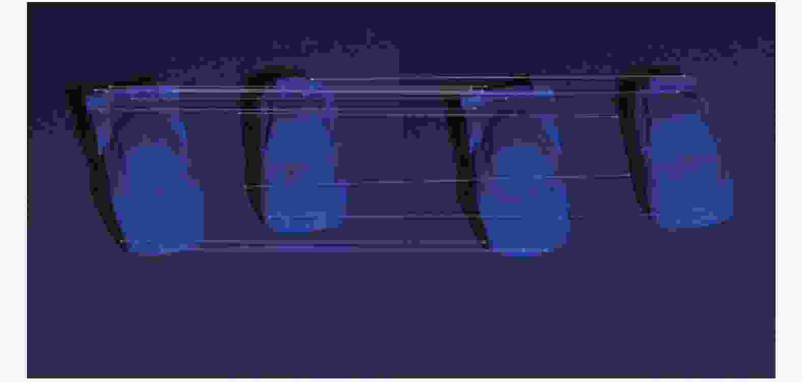
图 4 SIFT算法得到的特征点及其对应关系
Figure 4. Feature points obtained by SIFT algorithm and their corresponding relations
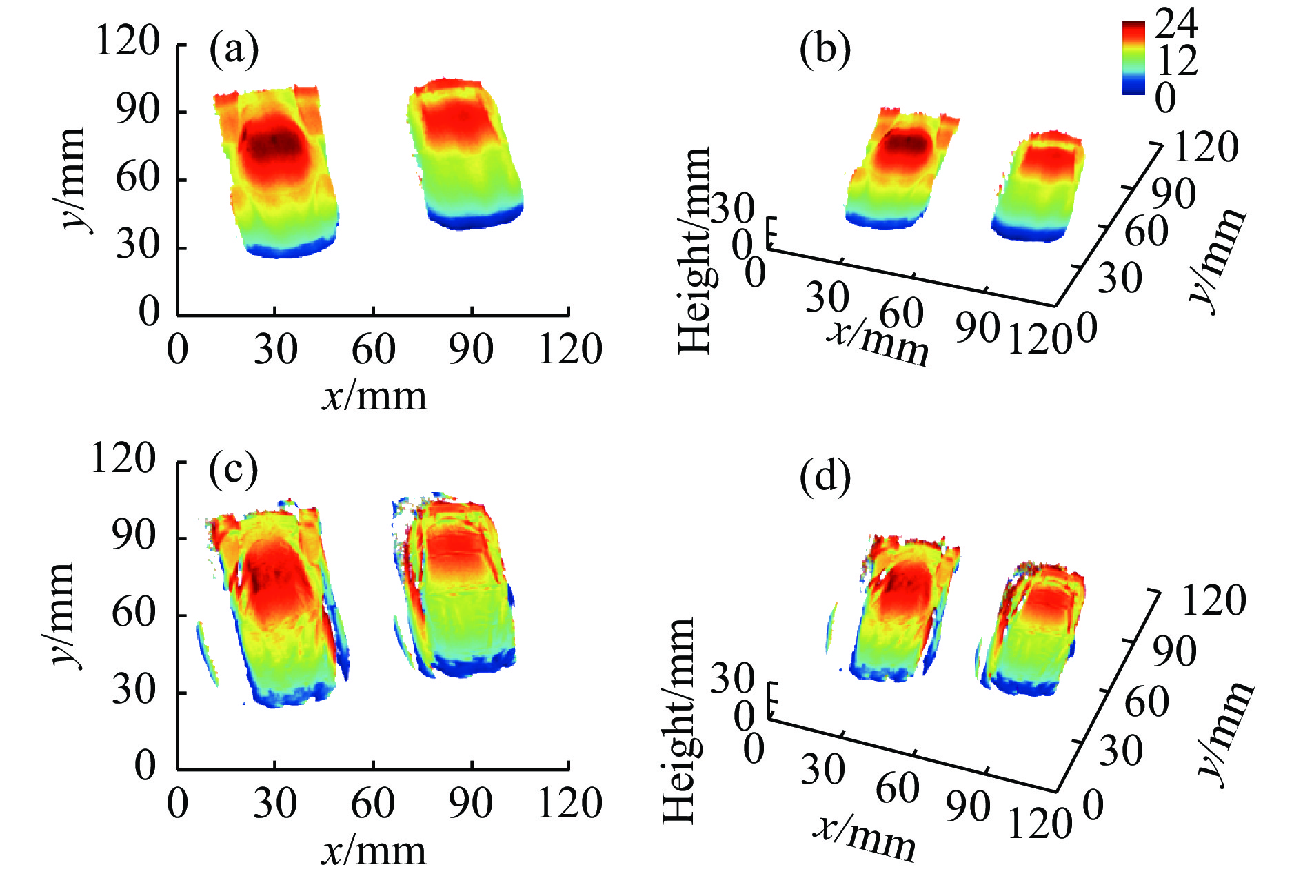
利用得到的每个目标物体的旋转平移矩阵计算出补偿了运动误差的正确相位,并使用双频率解包裹算法,对运动物体进行了三维重构,结果如图5(a)~(b)所示。结果表明本算法消除了运动引起的测量误差,得到了正确的物体三维形貌。为了对比实现效果,图5(c)~(d)是传统相移法的重构结果。可明显看出运动引起的误差。

图 5 基于传统的PSP算法和文中提出算法重构结果。(a)~(b)使用文中提出的算法的结果;(c)~(d)使用传统PSP算法的结果
Figure 5. Traditional PSP algorithm and the algorithm proposed in this paper are used for reconstruction. (a)-(b) the results of the algorithm proposed in this paper; (c)-(d) the results using traditional PSP
-
文中提出了一种基于相移法的多目标运动物体三维重构方法,通过设置被测物体目标区域,改算法可自动识别、跟踪多个被测物体,进而获得不同物体运动的数学描述,最终实现多个被测物体的三维重构。该算法实现了多个被测物体具有不同二维运动时的三维重构,具有较强的工业应用价值。
3D reconstruction of multi-target moving objects based on phase-shifting method
-
摘要: 相移法可实现静态物体三维形貌的高精度重构,对于运动物体形貌重构则误差较大。其根本原因为相移法需要多个条纹图进行物体重构,而传统相移法理论没有包含物体的运动信息,无法描述物体运动对相位的影响。导致当物体在条纹图间发生运动时测量误差较大。针对以上问题,提出了一种利用物体运动信息对多个二维运动物体进行三维重构的新方法。不同的被测物体可具有不同的运动轨迹。首先,对多个被测物体进行识别并确定目标区域;然后,采用KCF算法对物体进行跟踪并使用SIFT算法提取物体运动前后的特征点,分别估计描述物体运动的旋转平移矩阵。将运动信息带入条纹描述方程中,获得包含运动信息的三维重构模型,最终采用最小二乘法提取正确的相位值。结果证明:该方法能有效地减少由物体运动引起的测量误差,扩展了三维测量的应用范围,具有较高的工业应用价值。Abstract: Phase shifting profilometry (PSP) can reach high accuracy for the 3D shape measurement of static object. However, errors will be introduced when moving object was reconstructed. The fundamental reason was PSP required multiple fringe patterns to reconstruct the object and the traditional PSP did not contain movement information. Aiming at the above, a new method for the 3D reconstruction multiple 2D moving objects was proposed. Different objects can have different movement. Firstly, the multiple objects were identified and the areas of interests are defined. Then, the KCF algorithm was used to track the moving object and SIFT algorithm was used to retrieve the feature points of the object before movement and after movement. The rotation matrix and translation vector describing the movement was then obtained. With the help of the reconstruction model with movement information, the least-square algorithm was employed to retrieve the correct phase value. The results show that the proposed method can reduce the errors introduced by the movement and has the potential to be applied in industrial field.
-
Key words:
- phase shifting profilometry /
- 3D reconstruction /
- phase measurement /
- fringe analysis
-
图 1 捕获到的条纹图。(a)~(c)三步PSP捕捉到的运动物体条纹图案
Figure 1. Captured fringe pattern. (a)-(c) The fringe pattern of the moving object captured by the three-step PSP
图 2 不同通道中的图像。(a)拍摄的物体图像;(b)图2(a)的红色通道图像;(c)图2(a)的蓝色通道图像
Figure 2. Images in different channels. (a) Captured object image; (b) Red channel image of Fig. 2 (a); and (c) the blue channel image of Fig. 2 (a)
图 3 物体定位与跟踪。(a)测量前手动标出的物体目标区域;(b)连续图像中KCF的物体跟踪结果
Figure 3. Targeting and tracking. (a) Identified area of object before movement; (b) Tracking result by KCF
图 4 SIFT算法得到的特征点及其对应关系
Figure 4. Feature points obtained by SIFT algorithm and their corresponding relations
-
[1] Feng Shijie, Zuo Chao, Tao Tianyang, et al. Robust dynamic 3-D measurements with motion-compensated phase-shifting profilometry [J]. Optics and Lasers in Engineering, 2018, 103: 127−138. doi: 10.1016/j.optlaseng.2017.12.001 [2] Liu Ziping, Zibley Peter, Zhang Song. Motion-induced error compensation for phase shifting profilometry [J]. Optics Express, 2018, 26(10): 12632−12637. doi: 10.1364/OE.26.012632 [3] Flores Jorge L, Stronik Marija, Munoz Antonio, et al. Dynamic 3D shape measurement by iterative phase shifting algorithms and colored fringe patterns [J]. Optics Express, 2018, 26(10): 12403−12414. doi: 10.1364/OE.26.012403 [4] Liu Xinran, Tao Tianyang, Wan Yingying, et al. Real-time motion induced error compensation in 3D surface-shape measurement [J]. Optics Express, 2019, 27(18): 25265−25279. doi: 10.1364/OE.27.025265 [5] Qian Jiaming, Tao Tianyang, Feng Shijie, et al. Motion-artifact-free dynamic 3D shape measurement with hybrid Fourier-transform phase-shifting profilometry [J]. Optics Express, 2019, 27(3): 2713−2731. doi: 10.1364/OE.27.002713 [6] Lu Lei, Xi Jiangtao, Yu Yanguang, et al. New approach to improve the accuracy of 3-D shape measurement of moving object using phase shifting profilometry [J]. Optics Express, 2013, 21(25): 30610. doi: 10.1364/OE.21.030610 [7] Lu Lei, Xi Jiangtao, Yu Yanguang, et al. Improving the accuracy performance of phase-shifting profilometry for the measurement of objects in motion [J]. Optics Letters, 2014, 39(23): 6715. doi: 10.1364/OL.39.006715 [8] Lu Lei, Ding Yi, Luan Yinsen, et al. Automated approach for the surface profile measurement of moving objects based on PSP [J]. Optics Express, 2017, 25(25): 32120. doi: 10.1364/OE.25.032120 [9] Lu Lei, Luan Yinsen, Su Zhilong, et al. General model for phase shifting profilometry with an object in motion [J]. Applied Optics, 2018, 57(36): 10364. doi: 10.1364/AO.57.010364 [10] Lu Lei, Jia Zhaoyi, Luan Yinsen, et al. Reconstruction of isolated moving objects with high 3D frame rate based on phase shifting profilometry [J]. Optics Communications, 2018, 12: 092. [11] Henriques J F, Caseiro R, Martins P, et al. High-speed tracking with kernelized correlation filters [J]. IEEE Transactions on Pattern Analysis and Machine Intelligence, 2015, 37(3): 583−590. doi: 10.1109/TPAMI.2014.2345390 -

 点击查看大图
计量
- 文章访问数: 1077
- HTML全文浏览量: 379
- 被引次数: 0


