


-
C/SiC复合材料作为新型空间光机结构材料具有以下优异的特性[3]:
(1)低密度,根据碳纤维含量的不同,密度在1.7~2.7 g·cm−3 之间可调整;
(2)高比刚度、高比强度;
(3)低热胀系数,且可根据组分比来调节。由于碳纤维热胀系数的各向异性,通过改变空间编织结构可实现某一方向近零热胀系数的设计;
(5)热导率高,抗热震性能好;
(6)空间环境适应性好,耐腐蚀、耐辐射;
(7)整体性能可设计。
目前制备C/SiC复合材料的工艺主要有4种[4]:先驱体浸渍—裂解工艺(PIP)、化学气相渗透工艺(CVI)、液相渗硅反应烧结工艺(LSI)和气相渗硅反应烧结工艺(GSI)。这些工艺各有优劣,可通过某些混合工艺的形式来提高材料的综合性能、缩短研制的周期。
-
德国、日本、美国等航天强国在C/SiC复合材料应用于空间遥感领域的研究上走在世界前列[5-7]。
德国ECM公司基于液相渗硅法(LSI)制备出C/SiC复合材料,商品名为Cesic,密度为2.65 g·cm−3,模量为249 GPa,可在30~100 K范围内实现零膨胀[8-9]。日本三菱电气公司在此基础上做出改进,通过在碳纤维毡体里面混杂一系列不同尺寸的短切碳纤维,开发出商品名为HB-Cesic的C/SiC复合材料,进一步提高弯曲强度、弹性模量等性能[10-12]。这两种材料在反射镜制备上均有不少商业化应用,例如法国SPIRALE-A和SPIRALE-B卫星空间相机上采用了口径800 mm的HB-Cesic反射镜;GREGOR空间望远镜上口径分别为1500、420、360 mm的主镜、次镜、副镜均采用了Cesic材料;日本则针对SPICA空间望远镜研制了口径3 m以上的HB-Cesic反射镜[13]。但C/SiC复合材料在支撑结构方面公开信息较少,集中在光具座、镜筒等制备上[14-15]。
国内正针对C/SiC复合材料在空间遥感光机结构的应用积极开展研究,目前有北京空间机电研究所、中国科学院长春光学精密机械与物理研究所、哈尔滨工业大学、国防科技大学等科研院所,聚焦于轻质化、低热胀系数的反射镜零部件的研制上。
-
文中针对某大口径同轴三反相机次镜承力筒展开研究。该次镜承力筒采用薄壁筒式、支撑三翼、次镜座的组合形式[16-17]。次镜承力筒的外径为Φ1200 mm,高度为405 mm;支撑三翼的壁厚为8 mm。如表1所示,可选的支撑结构材料有钛合金TC4、Invar、C/SiC。
表 1 可选材料特性
Table 1. Properties of alternative materials
Sample name TC4 Invar C/SiC Density/kg·m-3 4.4×10³ 8.18×10³ 2.4×10³ Tensile modulus/GPa 114 150 110 Thermal conductivity/
W·(m·K)−18.8 1.47 4.6 Linear expansion coefficient/K−1 8.9×10⁻⁶ 0.55×10⁻⁶ 2×10⁻⁶ 文中对比两种材料方案:方案一采用钛合金TC4铸造成型;方案二采用C/SiC整体成型,对外接口则采用TC4预埋件,以弥补C/SiC机械切削加工工艺性差的缺点[18]。针对两种方案进行不同工况下的仿真,忽略接口影响,建立统一模型,以次镜承力筒上法兰安装孔为固定约束,分析TC4和C/SiC两种材料的结构性能差异。对于连续纤维增韧C/SiC材料而言,其材料特性为各向异性,但考虑到次镜承力筒为薄壁结构,整体性能主要表现为面内拉压,因此仿真时按各向同性作简化计算。
-
在仿真软件中建立有限元模型,如图1所示,对不同材料方案下次镜承力筒的质量、模态、热变形进行校核。
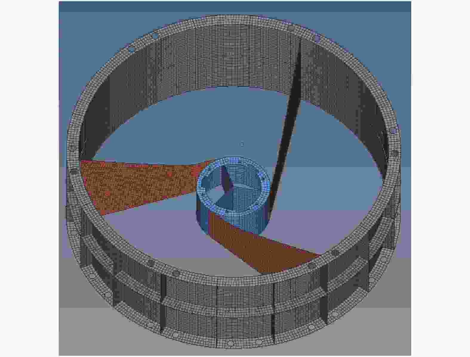
图 1 次镜承力筒有限元模型
Figure 1. Finite element model of secondary mirror bearing cylinder
-
方案一、方案二中次镜承力筒的质量分别为58.7 kg和32 kg。可以看出,采用C/SiC整体成型方案,次镜承力筒质量相比采用钛合金铸造成型方案质量下降了26.7 kg,减轻了45.5%。
-
文中研制次镜承力筒的设计要求为一阶固有频率大于100 Hz。分析时次镜承力筒加上次镜部件作为负载,对比两种方案下组件的固有频率和一阶振型。仿真结果如表2和图2所示。
表 2 两种方案结构的固有频率
Table 2. Natural frequencies of the structure with two schemes
Sample name TC4 C/SiC 1st natural frequency/Hz 183 204 2nd natural frequency/Hz 236 253 3rd natural frequency/Hz 237 254 4th natural frequency/Hz 284 335 
图 2 两种方案结构的一阶振型
Figure 2. First order vibration model of the structure with two schemes
从表2可见,两种方案均具有足够的刚度,能够满足设计要求。但C/SiC复合材料整体成型结构性能更优,其前四阶固有频率分别比采用TC4铸造成型结构提高了11.5%、7.2%、7.2%和18%。
-
分析次镜承力筒在均匀温升4 ℃工况下的变形情况,从图3可见,该工况下钛合金结构变形在10 μm级,而C/SiC结构变形要小一个量级。反映到次镜面形上,如表3所示,C/SiC结构支撑下的反射镜面形RMS为4.01 nm,相较前者提升约12%。
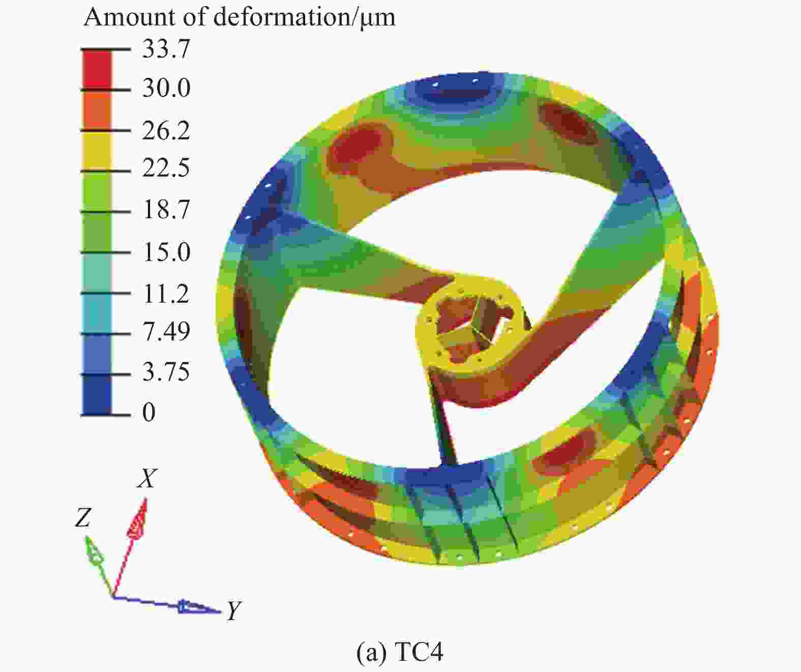

图 3 温度云图
Figure 3. Temperature cloud picture
表 3 均匀温升对面形的影响
Table 3. Influence of uniform temperature rise on the surface shape
Name RMS wavefront Image TC4 4.53 nm 
C/SiC 4.01 nm 
-
在经过预制体编织、热解碳制备、致密化、粗精加工等一系列流程之后,如图4所示,完成次镜承力筒的实物研制。通过对研制过程中的随炉试片进行检测,主要物理性能见表4。

图 4 次镜承力筒
Figure 4. Secondary mirror bearing cylinder
表 4 试片物理特性
Table 4. Physical properties of the sample
Name C/SiC Density/kg·m−3 2.31×10³ Tensile modulus/GPa 118.6 Thermal conductivity/W·(m·K)−1 4.95 Linear expansion coefficient/K−1 1.72×10⁻⁶ 在次镜承力筒的预留孔位处利用硅橡胶粘接嵌套,同时备紧螺母,如图5所示,并对嵌套端面进行精加工,以达到设计的尺寸精度。

图 5 安装嵌套后的次镜承力筒
Figure 5. Secondary mirror bearing cylinder after nesting
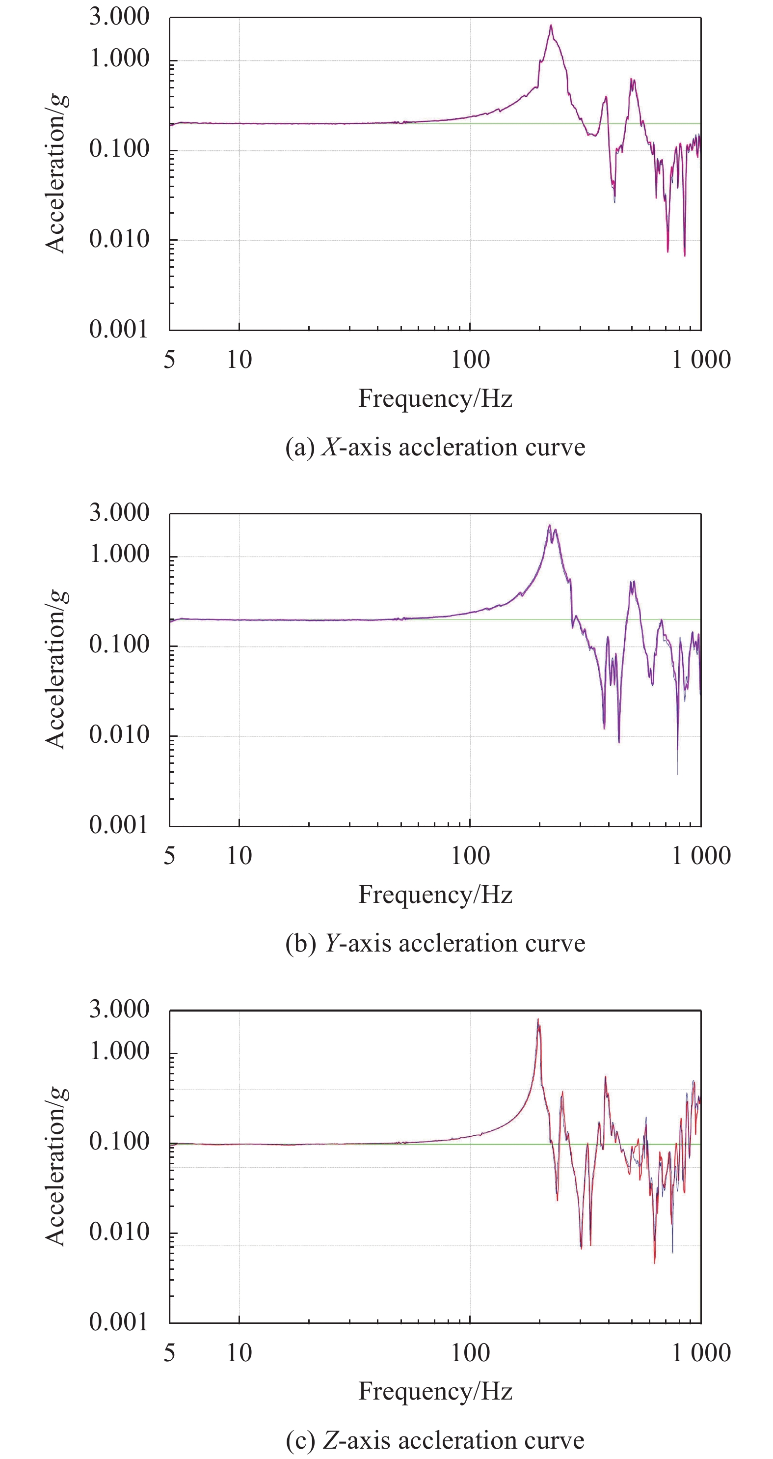
对次镜承力筒开展三个方向的力学环境试验考核,包括鉴定级正弦(频谱区为5~100 Hz,幅值分别为2、4.5、7.5、15 g)和随机振动试验(频谱区为10~2 000 Hz,总均方根加速度4 grms)。次镜承力筒X向振动基频为223 Hz,Y向振动基频为220 Hz,Z向振动基频为196 Hz,且经过正弦振动和随机振动之后特征级试验曲线复核较好,如图6所示,频漂小于1%,说明C/SiC次镜承力筒结构性能稳定。

图 6 振动前后的扫频曲线。 (a) X向振动;(b) Y向振动;(c) Z向振动
Figure 6. Frequency sweep curve before and after vibration. (a) X direction vibration; (b) Y direction vibration; (c) Z direction vibration
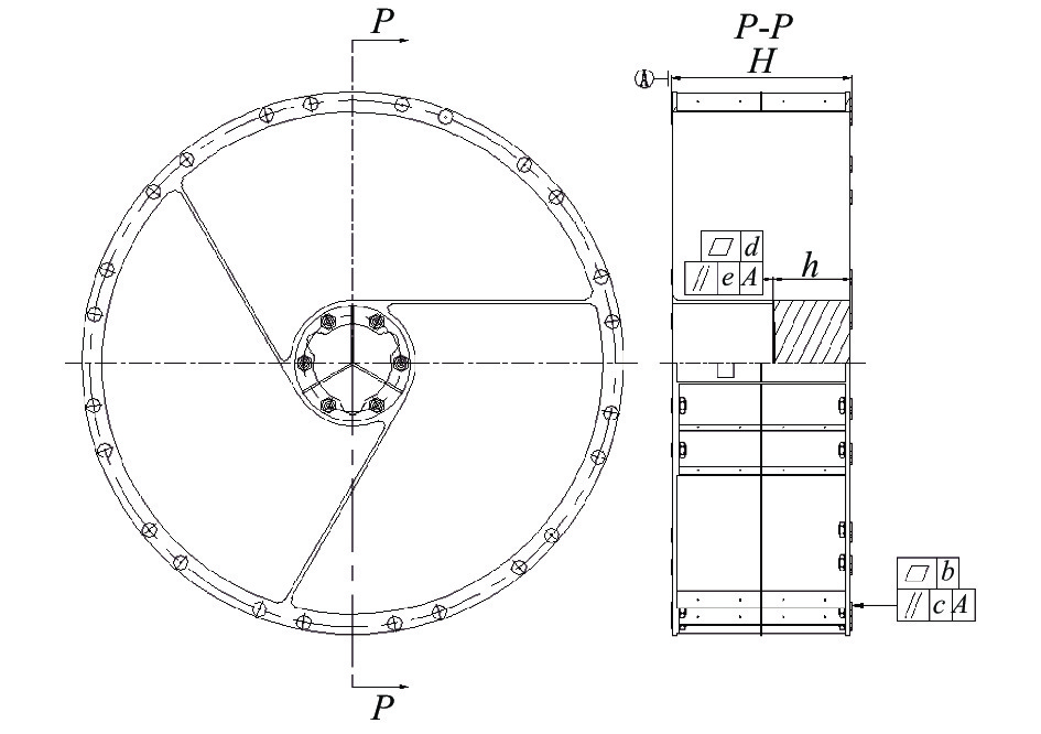
为考核振动过程中次镜承力筒的变形情况,用三坐标在振动试验前后对结构进行精密测量。如图7所示,主要考察以下重要参数:

图 7 结构重要参数
Figure 7. Vital parameters of the structure
A—下法兰嵌套面,作为基准;
b—上法兰嵌套面的平面度;
c—上法兰嵌套面相对下法兰嵌套面的平行度;
d—次镜座嵌套面的平面度;
e—次镜座嵌套面相对下法兰嵌套面的平行度;
h—次镜座嵌套面与上法兰嵌套面的距离;
H—下法兰嵌套面与上法兰嵌套面的距离。
如表5所示,振动前后测量数据有所变化,表明结构在振动中存在应力释放变形。但鉴于三坐标自身测量精度为微米级,而振动试验引起次镜支撑筒嵌套面的测量偏差(2.6、1.6、6.5、2.9、11.9、9.7 μm)在同一量级,可以认为C/SiC次镜支撑筒具有优异的位置稳定性,能够满足大口径空间望远镜对次镜支撑结构的要求。
表 5 振动前后结构测量
Table 5. Structure measurement before and after vibraton
Sample name Before vibration
/mmAfter vibration
/mmAmount of change
/mmb 0.0265 0.0291 0.0026 c 0.1283 0.1299 0.0016 d 0.0108 0.0173 0.0065 e 0.1153 0.1182 0.0029 H 405.0046 404.9927 −0.0119 h 178.3791 178.3694 −0.0097 -
文中介绍了C/SiC复合材料在国内外空间遥感领域的应用情况,分析了钛合金材料和C/SiC复合材料作为某大口径空间望远镜次镜承力筒材料时质量、振动模态和热变形。结果表明,在该次镜承力筒上应用C/SiC复合材料,相比钛合金材料,质量减小45.5%,一阶固有频率提高11.5%,同时具备较好的热稳定性。基于C/SiC复合材料设计,最终研制而成的次镜承力筒经严苛的力学环境分析,X、Y、Z三个方向特征级扫描试验的响应曲线重合良好,结构性能稳定。可以预见C/SiC材料在未来空间遥感器支撑结构的应用上将有更广泛的前景。
Application of C/SiC to secondary mirror bearing cylinder in large aperture space telescope
-
摘要: 设计并研制了基于C/SiC复合材料的大口径空间望远镜次镜承力筒。首先对C/SiC复合材料的特性以及在空间遥感器领域的应用进行了介绍。其次以某大口径空间望远镜次镜承力筒为例,对不同材料下次镜承力筒的质量、力热性能进行了对比。仿真分析表明:设计的C/SiC复合材料次镜承力筒低至32 kg,相比钛合金筒减轻45.5%;基频为204 Hz,满足设计要求;更易于控制热变形对反射镜面形的影响。最终完成了C/SiC复合材料次镜承力筒的研制和主要物理性能的检测,并进行了力学振动试验考核,对振动前后结构的三坐标测量数据进行了比对。结果表明:次镜承力筒组件的基频良好,振动试验前后频漂低于1%,结构的微位移变化量级在微米级。为应用C/SiC开展空间遥感器大尺寸整体成型支撑结构的设计提供有效的参考价值。Abstract: C/SiC composite material was applied to design of secondary mirror bearing cylinder in large aperture space telescope. Firstly, the material characteristics of C/SiC composite material and the applications in space optical remote sensor were introduced. Secondly, taking secondary mirror bearing cylinder of a large aperture space telescope as an example, the weight and structural-thermal performance based on different materials were compared. The analysis results indicate that C/SiC reduces the weight of secondary mirror bearing cylinder to 32 kg by 45.5% compared with titanium alloy cylinder. With natural frequency of 204 Hz, the structure meets the design requirement and can control the influence of thermal deformation on the shape of mirror. Finally, the C/SiC secondary mirror bearing cylinder was developed and the main physical properties were tested, and the mechanical vibration test was carried out, and the three-coordinate measurement data of the structure before and after vibration were compared. The results show that the fundamental frequency is excellent. Moreover, the frequency drift is less than 1% before and after the vibration test, and the micro displacement of the structure is in micron level. This paper provides several reference value for the design of large size integral bearing structure of space remote sensor by using C/SiC.
-
图 2 两种方案结构的一阶振型
Figure 2. First order vibration model of the structure with two schemes
图 6 振动前后的扫频曲线。 (a) X向振动;(b) Y向振动;(c) Z向振动
Figure 6. Frequency sweep curve before and after vibration. (a) X direction vibration; (b) Y direction vibration; (c) Z direction vibration
表 1 可选材料特性
Table 1. Properties of alternative materials
Sample name TC4 Invar C/SiC Density/kg·m-3 4.4×10³ 8.18×10³ 2.4×10³ Tensile modulus/GPa 114 150 110 Thermal conductivity/
W·(m·K)−18.8 1.47 4.6 Linear expansion coefficient/K−1 8.9×10⁻⁶ 0.55×10⁻⁶ 2×10⁻⁶  下载: 导出CSV
表 2 两种方案结构的固有频率
Table 2. Natural frequencies of the structure with two schemes
Sample name TC4 C/SiC 1st natural frequency/Hz 183 204 2nd natural frequency/Hz 236 253 3rd natural frequency/Hz 237 254 4th natural frequency/Hz 284 335
下载: 导出CSV
表 3 均匀温升对面形的影响
Table 3. Influence of uniform temperature rise on the surface shape
Name RMS wavefront Image TC4 4.53 nm C/SiC 4.01 nm
下载: 导出CSV
表 4 试片物理特性
Table 4. Physical properties of the sample
Name C/SiC Density/kg·m−3 2.31×10³ Tensile modulus/GPa 118.6 Thermal conductivity/W·(m·K)−1 4.95 Linear expansion coefficient/K−1 1.72×10⁻⁶
下载: 导出CSV
表 5 振动前后结构测量
Table 5. Structure measurement before and after vibraton
Sample name Before vibration
/mmAfter vibration
/mmAmount of change
/mmb 0.0265 0.0291 0.0026 c 0.1283 0.1299 0.0016 d 0.0108 0.0173 0.0065 e 0.1153 0.1182 0.0029 H 405.0046 404.9927 −0.0119 h 178.3791 178.3694 −0.0097
下载: 导出CSV
-
[1] Lu E, Yan C X, Wu Q W, et al. Research on adaptability of optical remote sensors in mechanical and space thermal environments [J]. Chinese Journal of Optics and Applied Optics, 2009, 2(5): 364-376. (in Chinese) [2] Zhang L H, Zhou H Z, Li M Z, et al. Review of aerospace composite technology [J]. Hi-Tech Fiber & Application, 2015, 40(3): 22-28. (in Chinese) [3] Zhang D K, Cao Y B, Liu R J, et al. Progress and prospect of C/SiC composites used in space opto-mechanical structures [J]. Materials Review, 2012, 26(13): 7-11. (in Chinese) [4] Huang L M, Zhang C R, Liu R J, et al. Process of C/SiC composites used in space mirror [J]. Aerospace Materials & Technology, 2016, 46(6): 26-29. (in Chinese) [5] Zhu X J, Xia Y W. Application of C/SiC composites in space optical system abroad [J]. Aerospace Materials & Technology, 2013, 43(4): 20-23. (in Chinese) [6] Li C J, Wang Z J, Zheng J H, et al. An overview on C/SiC composite mirror for space telescope [J]. Carbon, 2014(3): 13-19. (in Chinese) [7] Jiang T, Li R Z, Xie H Z. The development of large scale optical mirrors based on C/C-SiC [J]. Carbon, 2016(1): 24-29. (in Chinese) [8] Kroedel M, Kutter G S, Deyerlerl M. Short carbon-fiber reinforced ceramic cesic for optomechanical applications [C]//Proceedings of SPIE, 2003, 4837: 576-588. [9] Boy J, Kroedel M. Cesic light-weight SiC composite for optics and structure[C]//Proceedings of SPIE, 2005, 5868: 586807. [10] Kroedel M R, Ozaki T. HB-Cesic composite for space optics and structure[C]//Optical Materials & Structures Technologies III, 2007. [11] Devilliers C, Kroedel M. Cesic-optomechanical technology last development results and new HB-cesic, highly lightweighted space mirror development including corrective function[C]//7th International Conference on Space Optics, 2008. [12] Kroedel M, Ozaki T, Kume M, et al. Manufacturing and performance test of a 800 mm space optic[C]//Proceedings of SPIE, Advanced Optical and Mechanical Technologies in Telescopes and Instrumentation, 2008, 7018: 70180A. [13] Ozaki T, Kume M, Oshima T, et al. Mechanical and thermal performance of C/SiC composite for SPICA mirror[C]//Proceedings of SPIE, 2004, 5494: 132-141. [14] Papenburg U. Advanced ultra-lightweight C/SiC mirrors and opto-mechanical structures[C]//8th World Multi-Conference on Systemics, Cybernetics and Informatics, 2004. [15] Krodel M, Hofbauer P. Ultra-lightweighted HB-Cesic one-meter mirror demonstrator[C]//International Conference on Space Optics, 2010. [16] Liu P, Huang Q L, Yang J K. Research on support structure between primary and secondary mirror in large-aperture and long-focal-length space camera [J]. Spacecraft Recovery Remote Sensing, 2014, 35(3): 60-67. (in Chinese) [17] Lu X M, Jia J J, Zhou C L, et al. Optimization design of primary and secondary mirror supporting tube for space telescope [J]. Journal of Tianjin Polytechnic University, 2018, 37(4): 84-88. (in Chinese) [18] Wang Y X, Wang B, Ren J Y. Improvement of carbon fiber support structure and topology optimization design for space camera [J]. Infrared and Laser Engineering, 2009, 38(4): 702-704. (in Chinese) doi: 10.3969/j.issn.1007-2276.2009.04.027 -

 点击查看大图

计量
- 文章访问数: 104
- HTML全文浏览量: 28
- PDF下载量: 38
- 被引次数: 0

