


 下载:
下载:


-
在日趋复杂的高烈度空战环境中,准确快速地感知周边环境及威胁目标,精准完成末端防御措施释放和机动规避已经成为传统机载末端自卫技术发展的瓶颈之一。未来机载认知型末端防御技术必须具备多域感知、智能化决策、在线实时效能评估和持续自主执行的能力,将飞行员从防御性任务中解放出来,更好地专注于作战任务。机载自卫电子对抗系统智能决策算法的准确度和有效性依赖于大量的飞试和对抗数据,但是飞行试验存在组织困难、成本高昂、偶发因素较多和结果重现性差等诸多问题,亟需通过战术仿真开展飞试数据重现和数据推演,为飞机末端防御智能决策算法提供数据支持和校验手段。
随着信息科学与计算机技术的飞速发展,众多的军事研究从代价昂贵的单纯试验演练转变成了先仿真后验证的效高价廉的研究形式,战术仿真系统对于武器装备研发和战术使用研究的重要意义日益凸显。美国莱特帕德森研究与开发中心研发的动态红外导弹评估系统(DIME),以色列研发的红外场景仿真系统(IRSG),英国Chemring防务公司的全数字目标特征模拟系统(CounterSim),构建了大量封装好的舰船、飞机、车辆的红外和光电模型,基于3D场景模拟技术,可以真实再现海陆空等复杂场景下仿真目标的工作状态;法国OKTAL-SE公司开发的多传感器战场建模系统(SE-WORKBENCH)能够实现红外、毫米波、SAR成像等多频段三维场景合成建模,可以模拟传感器检测算法,评估干扰和制导效能[1-3]。
文中建立的飞机末端防御红外对抗仿真系统采用全数字仿真评估方法,基于飞机、面源、多点源和激光定向干扰的干扰作用机理,融合各类干扰手段的干扰特性和效能,虚拟构建机载末端防御场景下的复杂光电环境,模拟飞机、来袭导弹、多型红外诱饵的红外信号、运动、形态及扩散等物理特征在时域、空域及能量域的变化,实现弹目逼近场景中飞机机动样式和诱饵干扰效能的仿真分析、数据推演和作战效能评估,支撑飞机末端干扰技术指标体系优化和红外对抗决策算法研究。
-
飞机末端对抗红外仿真系统在并行仿真环境中实现交战场景中载机目标特性、诱饵辐射运动特性和复杂战场环境的红外特性建模,根据导引头观察角和弹目距离,实时生成导引头内红外图像,支持导引头抗干扰目标检测与飞行控制仿真,支持导弹抗干扰与飞机末端防御双方作战对抗效能评估。
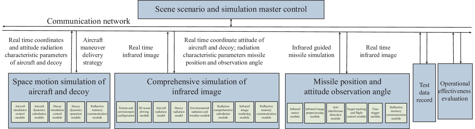
红外仿真系统内包含场景想定与系统总控、飞机诱饵空间运动仿真、红外图像综合仿真、红外制导导弹仿真、试验数据记录和作战效能评估六个组成单元,各单元通过反射内存网络实现通信与交互,仿真系统整体架构如图1所示。

图 1 仿真系统整体架构图
Figure 1. Overall architecture of simulation system
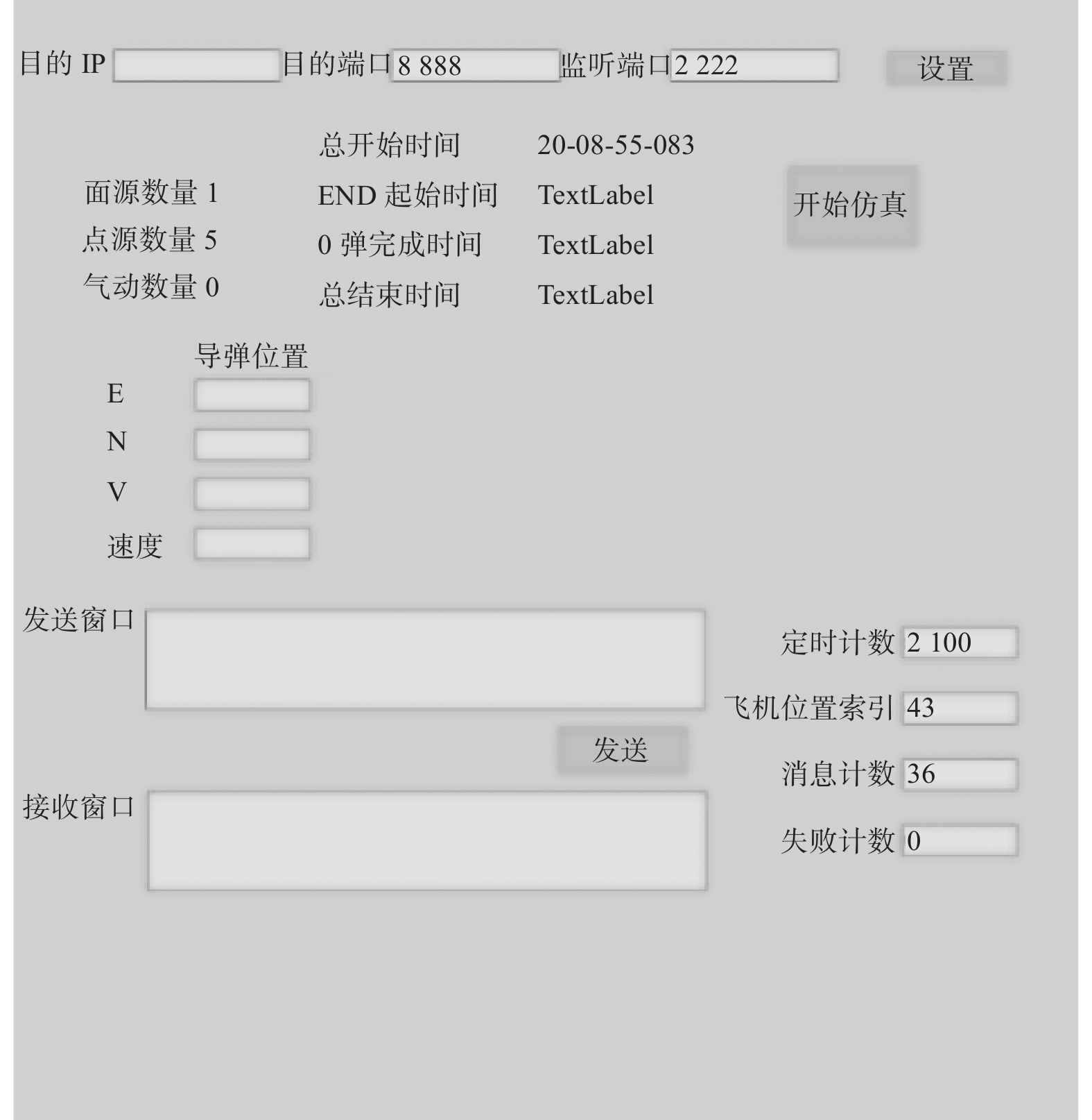
场景想定与系统总控单元用于实现场景初始化文件配置、仿真系统参数设置、网络节点管理和仿真节拍控制。
飞机及诱饵空间运动仿真单元包含飞机仿真控制、飞机动力学运算、诱饵仿真控制、诱饵动力学运算和反射内存通讯等功能模块,主要功能为接收场景想定初始化参数、飞机初始位置、机动样式、诱饵投放策略和节拍控制指令,调用诱饵运动扩散模型和飞机六自由度模型,计算飞机和诱饵实时位置信息、飞机姿态信息、扩散状态与辐射控制参数。
红外图像综合仿真单元包含地形与环境配置、三维场景驱动、飞机辐射模型、诱饵辐射模型、环境辐射与天气模块、辐射综合计算、红外图像渲染和反射内存通讯模块。红外图像综合仿真单元通过调用飞机和诱饵辐射模型,结合观测角、位置信息、姿态信息、扩散状态与辐射控制参数,与地形模型、环境场景模型和天气模型进行综合计算和叠加渲染。为了保证仿真系统红外图像输出的真实性,减轻数据同步压力,在仿真中,采用辐射控制参数描述飞机和诱饵的辐射面积、辐射温度和映射关系,最终生成导引头投影面的实时红外图像数据。
红外制导导弹仿真单元包含红外传感器、图像前处理、抗干扰检测、目标跟踪与飞控、引信触发和反射内存通信等模块。通过对视场内的实时红外图像进行预处理和抗干扰检测输出目标空间位置和弹目距离预测值,调用导引和飞控算法,实现导弹控制和目标跟踪,引信触发模块根据弹目距离预测值判断引信启动时机[4-5]。
试验数据记录单元逐帧记录总线上的通信数据,作战效能评估单元通过反演仿真数据,得出干扰或抗干扰作战成功率。
-
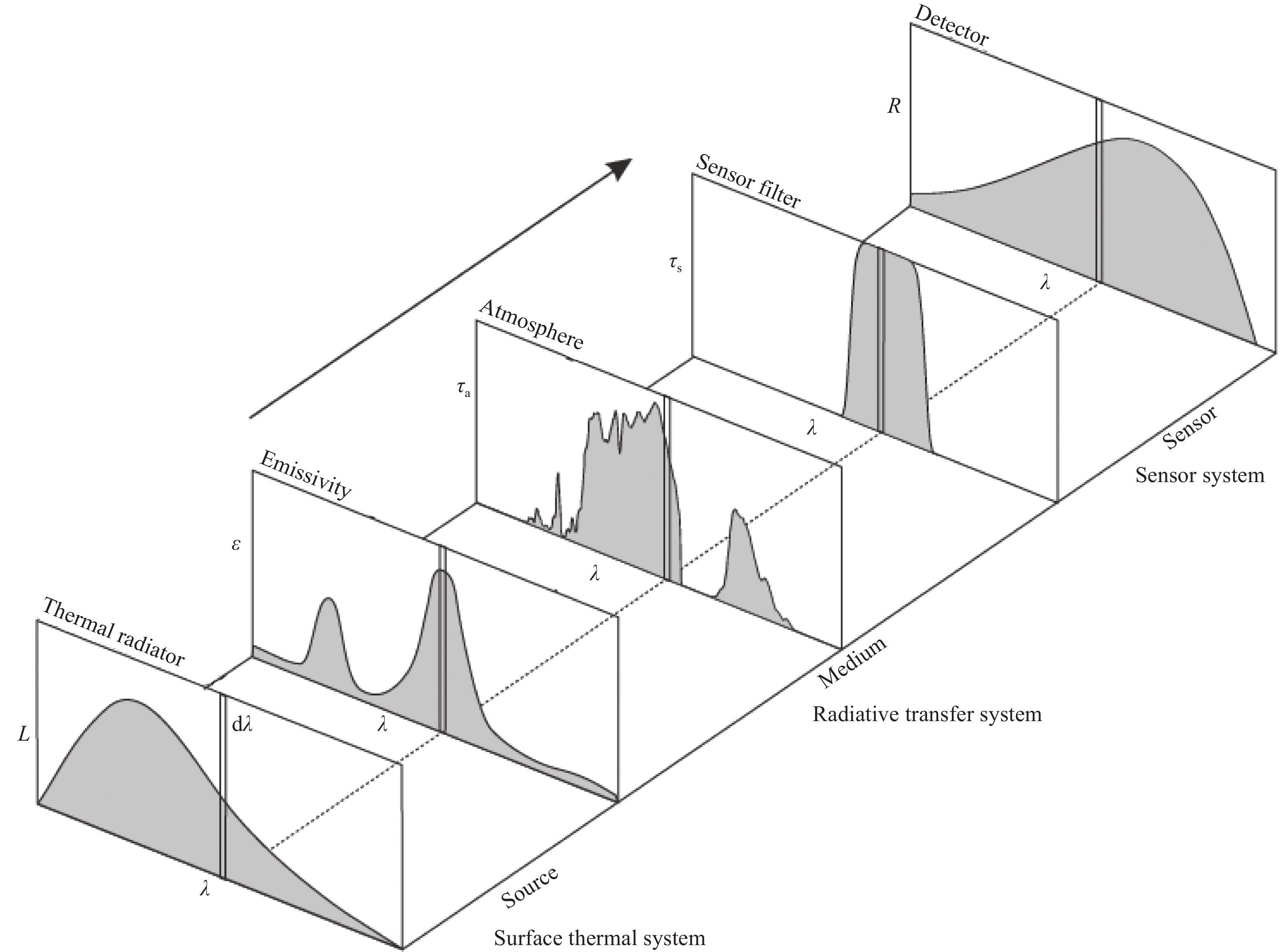
首先根据飞机红外辐射特性建立飞机排气系统和机体的红外辐射计算模型,然后考虑辐射传输路径上的大气衰减及探测器接收到的背景辐射,求解探测器视场内的目标和背景辐射亮度;最后将亮度值进行灰度量化,生成飞机的红外灰度图像,并根据所得图像求解飞机的红外辐射强度。
得到蒙皮温度场后,将蒙皮看作灰体,应用普朗克定律和基尔霍夫定律可得蒙皮自身辐射的红外辐射亮度,其计算公式为:
$$L_{\rm s}=\dfrac{\varepsilon}{\pi} \int_{\lambda_1}^{\lambda_2} \dfrac{c_1}{\lambda^5\left[{\rm e}^{c_2 /(\lambda T)}-1\right]}{\rm{ d}} \lambda $$ (1) 式中:ε为蒙皮发射率,与蒙皮材料和波长有关,对于飞机蒙皮材料通常可取ε=0.8;c1与c2为辐射常数。
蒙皮面元的红外辐射亮度等于自身辐射亮度与反射太阳辐射亮度之和,即
$$ L=L_{\rm s}+L_{\rm sun} $$ (2) 根据飞机的红外计算模型,分析计算结果得到飞机红外辐射的光谱特性、方位特性,以及发动机状态、飞行速度、高度等因素对飞机红外辐射的影响[6]。
-
面源红外干扰弹投放后在载机附近迅速扩散开来形成红外干扰云团,其与被保护载机的红外图像相似,或改变载机的红外图像特征,欺骗红外成像制导导弹,继而诱使红外成像制导导弹偏离被保护的载机[7]。
面源红外干扰弹作为一种自燃金属箔片,其辐射模型受到材料的物理性能和化学反应、空气气流的热交换以及干扰弹扩散规律等决定。由于燃烧反应物质有限,干扰弹红外辐射随时间必然是一个先增大后减小的过程,红外辐射强度随时间的变化规律如图2所示。
图 2 不同波段下的面源辐射强度仿真结果
Figure 2. Simulation results of area source radiation intensity under different bands
-
多点源红外干扰弹发射后形成多个分散的点源红外干扰弹,连续投放后形成多个点状发热体。采用多发齐射或多方位齐射时,可迅速在一定空域形成红外高辐射区,并在导引头瞬时视场内形成持续的多个干扰源,将目标信号淹没,导引头就必须处理多组脉冲信号,降低了导引头检测目标的概率,红外导引头即使启动了抗干扰措施,但因探测器的噪声几何级数增大,而难以提取有效的制导信号,从而起到保护载机的作用[8-11]。
-
点面复合红外干扰弹是点源与面源红外干扰弹的物理组合,通过在单发干扰弹内同时装填点源/面源干扰载荷,发射后在一定空间区域形成辐射强度大于载机巡航态、辐射面积大于载机、能有效抑制红外制导导弹的多种抗干扰检测措施的面源红外诱饵辐射云团和红外辐射源。面源红外辐射云团和红外辐射源与载机同处于来袭导弹导引头的视场内,点红外辐射源与目标红外辐射逐渐融合,严重破坏目标红外辐射特征,通过强红外辐射干扰源对红外制导导弹实施压制、转移式干扰;面源红外辐射云团能够使导引头的跟踪中心逐渐偏向红外辐射源,并能够掩盖和歪曲红外成像探测系统所要观察的目标征候及信号特征,混淆目标的大小、位置和数量,从而有效降低导引头的目标识别与跟踪性能。
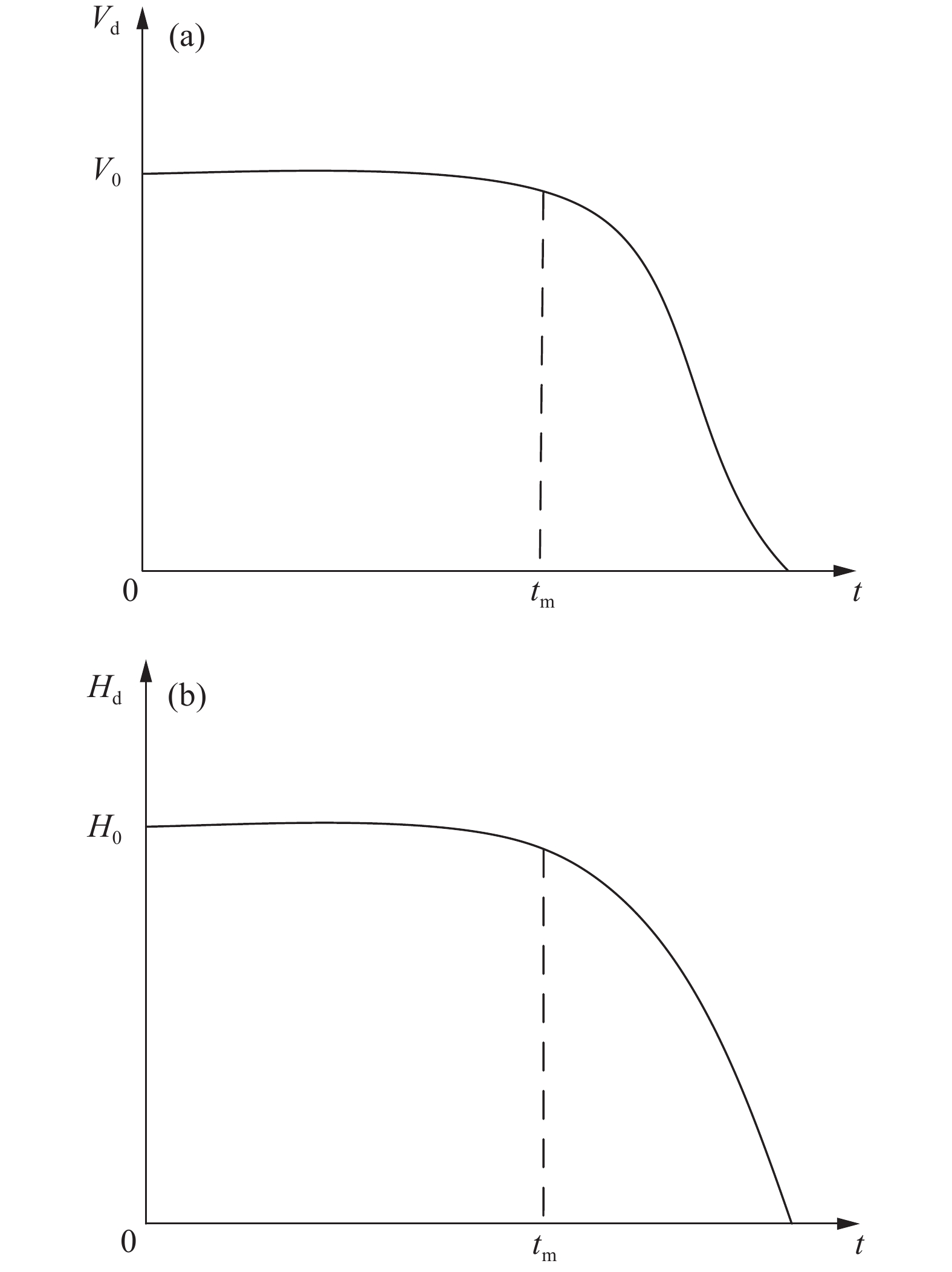
动力光谱红外干扰弹的运动特征为:发射后以发射时的初始绝对速度基本达到匀速平飞,装药燃尽后红外干扰弹减速下降。其速度、高度的变化如图3所示。图中,
$ V_{0} $ 和$ H_{0} $ 为发射时的初始绝对速度和高度;$ t_{m} $ 为动力光谱红外干扰弹的有效作用时间。
图 3 动力光谱的速度特性与高度特性
Figure 3. Velocity and height characteristics of dynamic spectrum
-
红外定向干扰属于光电有源干扰,通过红外激光光源和跟踪瞄准转台向导引头发射激光光束,持续对红外制导导弹进行主动干扰压制,在验证试验中,利用中波红外激光对数千米外中波导引头进行照射,可在导引头视场内形成一定面积的干扰耀斑,实现有效干扰[12-13],如图4所示。
图 4 中波红外激光干扰红外导引头效果
Figure 4. Effect of medium wave infrared laser jamming infrared seeker
-
由于飞机、导弹在远距离时,其成像不能充满跟瞄系统的瞬时视场,可作为红外点源处理,跟瞄系统作用距离公式为:
$$ R=\left[\frac{\pi \cdot \delta \cdot \tau_{\rm a} \cdot \tau_{0} \cdot J \cdot D^{*} \cdot D_{0}^{2}}{4 \cdot \sqrt{A_{\rm d}} /\left(2 t_{\text {int }}\right) \cdot S N R}\right]^{1 / 2} $$ (3) 式中:
$ \delta $ 为信号峰值因子;$\tau_{\rm {a }}$ 为大气透过率,采用MOTRAN软件计算;$ \tau_{0} $ 为系统光学效率;D*为探测率;D0为跟瞄系统光学口径;Ad为探测器光敏元面积;$ t_{\text {int }} $ 为探测器积分时间;SNR为探测所需信噪比,取5;J为目标红外辐射强度。 -
大气相干长度为:
$$ r_{0}=\frac{C \lambda^{6 / 5}}{\left(C_{n}^{2} L\right)^{3 / 5}} $$ (4) 式中:
$ C $ 为常数,对于平面波,取0.185;${C}_{n}^{2}$ 为折射率结构特征参数,一般来说,近地面湍流强度可粗略分为三类:强湍流$ C_{n}^{2}=10^{-12} \mathrm{~m}^{+200} $ ,中湍流$ C_{n}^{2}=10^{-14} \mathrm{~m}^{+200} $ ,弱湍流$ C_{n}^{2}=10^{-16} \;{\rm{m}}^{-2 / 2} $ ;$ \lambda $ 为激光波长;$ L $ 为目标距离。在传输过程中受大气湍流影响,光斑发散角将放大,湍流放大系数为:
$$ A^{\prime}=\sqrt{\left(1+\left(\frac{D}{r_{0}}\right)^{2}\right.} $$ (5) 式中:
$ D $ 为激光发射装置的有效发射口径。激光束经敌方目标光学系统会聚后,照射到敌方探测器靶面上的光斑直径为:
$$ d^{t}=f \theta_{0} A^{t}+2.44 \lambda F $$ (6) 式中:
$ f $ 敌方光学焦距,$ f=D \times F $ ;$ \theta_{0} $ 为激光发射装置出射口的激光发散角;$ F $ 为敌方光学系统的F数。最终激光入射到敌方探测器上的激光功率密度为:
$$ E=P_{0} \tau_{\rm a} \tau_{0} \frac{A_{0} \cos \sigma}{\pi\left(L \theta_{0} A^{\prime} / 2\right)^{2} \times \pi\left(d^{\prime} / 2\right)^{2}} $$ (7) 式中:
$ P_{0} $ 为激光发射功率;$ \tau_{0} $ 为敌方光学系统的光学透过率;$ A_{0} $ 为敌方光学系统通光面积;$ \sigma $ 为攻击角。假设敌方光学目标的干扰阈值为
$E_{\text {th }}$ ,则当$E > E_{\rm th}$ 时,可成功干扰敌方目标。由上述各公式可迭代计算出红外定向干扰系统对目标的最大干扰距离$ L $ 。 -
(1) 红外特征实时解算
红外场景生成模块基于模型数据库中的几何特征和材质数据,并结合当前的大气环境数据,计算当前场景的红外辐射特征并输出红外仿真图像。模型基于真实的物理过程建立,考虑了大气的辐射、太阳直射、物体自身的吸收和散射等物理过程,能够真实还原当前场景的物理特征,如图5所示。
图 5 红外仿真模型
Figure 5. Infrared simulation model
(2) 红外场景仿真
根据前面建立的飞机、诱饵、激光定向干扰模型,将其注入到飞机末端对抗红外仿真系统,红外图像渲染模块主要包括外部激励数据通信、Vege Prime三维可视化渲染引擎、OndulusIR红外仿真解算引擎、三维模型库和光电属性材质库等部分。红外图像渲染模块的架构如图6所示。

图 6 红外图像渲染模块架构图
Figure 6. Architecture of infrared image rendering module
基于三维模型的几何特征和纹理特征,对模型所对应的材质进行分类、识别并定义各类材质的电磁散射、投射特性和红外辐射特性。这些和地理数据关联的模型参数存入统一的模型数据库中。这些模型的几何特征和物理材质将作为之后传感器仿真计算的基础。此时,则完成了传感器建模所需的战场或仿真环境建模。在三维可视化渲染工作中,根据外部数据激励(诱饵运动、扩散及辐射状态数据)定义诱饵在仿真环境中的相互位置、扩散运动参数,红外传感器相对目标的视角关系,实现当前仿真条件下的动态场景渲染。三维场景生成模块同时提供粒子系统和热点建模能力,基于粒子系统和热点建模能力实现对点源/多点/动力光谱诱饵源和面源诱饵源的图像渲染建模,根据控制信息实现红外干扰源的类型选择、触发机制、释放方向、粒子扩散方向、消隐轨迹、消隐时间、风速影响、红外特征等调节。
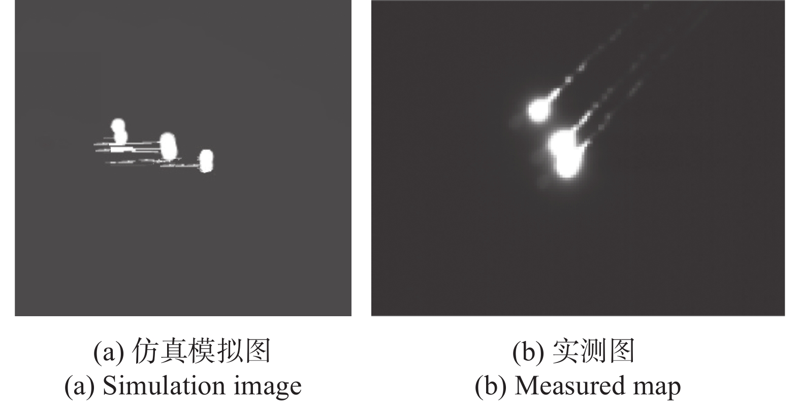
如图7、图8所示,通过前面建立的不同类型的干扰辐射模型,进行红外动态场景渲染,能较好地模拟导引头视场内的帧频红外图像和动态红外视景。图7对单发面源诱饵有效扩散下的红外场景仿真进行模拟,与实测数据进行对比,从扩散形状、运动趋势、红外辐射亮度等都能有效地模拟诱饵红外场景。图8对单发多点源的红外场景进行仿真模拟,与实测数据进行对比,在诱饵的形状、尾迹拖尾、辐射亮度等能真实模拟多点源诱饵在导引头视场内的特征。

图 7 面源的红外场景
Figure 7. Infrared scene of area source
图 8 多点源的红外场景
Figure 8. Infrared scene of multi-point source
通过利用可见光和红外场景构建、诱饵运动和辐射模型驱动、实时场景融合与可见光、红外场景输出,能有效地对实际作战场景下飞行状态下,导引头视场内的目标与诱饵动态红外特性、背景特征进行模拟仿真。同时通过飞机末端对抗仿真系统,对不同场景下仿真场景与实测场景进行对比分析,能有效地对不同场景的红外对抗进行仿真,为诱饵干扰效能评估提供逼真的红外对抗场景。
-
根据已建立的辐射模型和飞机末端对抗红外仿真系统,对不同作战环境、干扰场景的飞机末端防御进行仿真分析,调用红外仿真解算模块,根据三维场景生成模块中对目标、背景、干扰的位置定义,根据诱饵热力学参数、大气模型、传感器模型、热源模型等进行诱饵的红外特征解算计算出当前场景的红外辐射特征,实现空战场景下诱饵和目标的红外图像渲染[14-15]。根据红外图像渲染和模型解算,仿真得到飞机末端防御的红外对抗场景设定,如图9、图10所示。
根据飞机末端防御红外对抗的作战需求,通过建立的飞机末端对抗仿真系统,仿真得到典型作战场景下的面源、多点源、动力光谱、激光定向干扰作用的红外对抗场景,为红外干扰效能评估提供实时的红外对抗场景。

图 9 红外对抗场景的飞参数据
Figure 9. Flight parameter data of infrared countermeasure scene
图 10 干扰源作用下的红外对抗场景仿真
Figure 10. Simulation of infrared countermeasure scene under the action of jamming source
图 11 多点源和面源复合作用下的红外对抗场景仿真
Figure 11. Simulation of infrared countermeasure scene under the combined action of multi-point source and area source
-
结合典型作战场景对飞机末端防御对抗效能进行了仿真评估。仿真模型包括:数字化导引头、导弹飞控模型、飞机红外特征模型、飞机机动模型(加速、减速、盘旋、上升、俯冲、战斗转弯、滚筒等)、云雾等环境参数模型、地面地形环境模型、叠加地物、空天背景的可视化场景及红外辐射图像渲染模型、导弹命中飞机目标的命中点计算模型和脱靶量计算模型。
通过干扰手段典型的使用方式和干扰策略,定义单独投放多点源、面源干扰弹和使用红外定向干扰,以及组合使用多点源、面源和红外定向干扰时(图11),通过干扰效能仿真评估其干扰成功率。
-
根据飞机典型的作战态势和机动方式,对不同机动、导弹攻击方式、末端对抗的干扰诱饵和红外定向干扰使用方式进行仿真分析,评估飞机末端红外对抗干扰效能。定义导弹脱靶量为导弹命中率高低的判定标准,干扰成功率=1−导弹命中率。干扰效能仿真评估结果如图12所示。
根据数组的仿真结果对比分析,对不同干扰使用策略下的干扰成功率进行仿真计算,从图12(a)可知单独使用多点源干扰弹经过数次仿真的结果对比,干扰成功率在40%左右,干扰成功率相对稳定;从图12(b)可知单独使用面源干扰弹经过数次仿真结果的对比,干扰成功率在60%左右,干扰成功率相对稳定;从图12(c)可知单独使用红外定向干扰经过数次仿真结果的对比,干扰成功率在50%左右,同时会出现干扰不成功的情况;从图12(d)可知单组合使用多点源、面源和红外定向干扰经过数次仿真结果的对比,干扰成功率在90%以上,能有效地对抗来袭的红外制导导弹。
图 12 干扰成功率仿真结果图
Figure 12. Simulation results of interference success rate
图12仿真结果表明,单一使用多点源、面源、红外定向干扰等干扰手段的干扰成功率没法达到最优干扰效能。通过组合使用多点源和面源、多点源和红外定向干扰、面源和红外定向干扰三种干扰方式,具备干扰资源配置数量少、干扰效能高、干扰成功率大等优势。
-
结合飞机不同方向上的红外辐射特征,以及多点源红外干扰弹、多点源红外干扰弹、面源红外干扰弹和激光定向干扰的技术特点,可分析出飞机在对抗光学非成像和成像红外导弹导引头时红外对抗的策略。当来袭红外制导导弹距飞机较远时,飞机在红外导引头中显示为一个热点,此时采用多点源红外干扰弹,以质心干扰的方式诱骗红外导引头和增加导引头处理干扰信号数量,同时启动激光定向干扰设备跟踪搜索目标,对来袭导弹达到实施精确跟瞄;随着来袭导弹与飞机距离缩短,飞机在导引头中面积逐渐增大,导引头处于亚成像工作状态,此时组合释放多点源与面源红外干扰弹,同时发射红外定向激光,面源红外干扰云团与飞机图像融合,使导引头分辨不出目标,多点源红外干扰源以质心干扰方式诱骗导引头和迅速增大导引头处理干扰信号的数量,红外定向激光能在一定程度上致炫导引头,三者结合可大幅提升对干扰红外成像导引头的干扰效能;当红外导弹进一步靠近时,导引头能够对视场内目标清晰成像,此时通过持续释放面源红外干扰弹,同步输出红外定向激光,实现对导引头的图像和能量双重压制,提升干扰概率和飞机末端生存力。
-
为了研究飞机末端对抗红外干扰策略,建模分析了飞机红外特性、诱饵干扰特性、激光定向干扰特性和干扰作用机理,结合飞机末端防御的红外对抗态势,建立了飞机末端对抗红外仿真研究方法。结合点源红外干扰弹、面源红外干扰弹、红外定向干扰等红外对抗技术特点,开展了飞机对抗红外制导导弹的干扰决策原则研究,干扰手段组合使用策略和对抗效能。飞机末端防御红外对抗仿真逼着度高,能有效地对飞机末端红外对抗进行仿真评估分析和干扰策略研究。
Simulation of airborne terminal infrared countermeasure operational effectiveness
-
摘要: 为研究飞机末端红外对抗作战效能,通过建立红外对抗仿真系统,分别对飞机红外特性、诱饵干扰特性、激光定向干扰特性进行建模仿真,通过红外特征实时解算的方法建立红外对抗场景,结合不同作战环境、干扰场景的飞机末端防御,进行红外图像渲染和模型解算,为红外干扰效能评估提供实时的红外对抗场景。结合典型的作战态势和飞机机动方式,仿真分析了导引头视场内的目标与诱饵动态红外场景,进行飞机末端防御的不同干扰手段干扰效能评估和干扰使用策略研究。仿真结果表明,飞机红外对抗仿真系统能有效地对末端红外对抗作战效能和干扰策略想定进行研究。Abstract: In order to study the operational effectiveness of aircraft terminal infrared countermeasure, the infrared countermeasure simulation system is established to model and simulate the aircraft infrared characteristics, decoy jamming characteristics and laser directional jamming characteristics respectively. The infrared countermeasure scene is established by the method of real-time calculation of infrared characteristics to combine the aircraft terminal defense of different operational environments and jamming scenes. Infrared image rendering and model solving are carried out to provide real-time infrared countermeasure scene for infrared jamming effectiveness evaluation. Combined with the typical combat situation and aircraft maneuver mode, the dynamic infrared scene of target and decoy in the seeker field of view is simulated and analyzed, and the jamming effectiveness evaluation and jamming use strategy research of different jamming means for aircraft terminal defense can be carried out. The simulation results show that the aircraft infrared countermeasure simulation system can effectively study the operational effectiveness and jamming strategy formulate of the terminal infrared countermeasure.
-
图 2 不同波段下的面源辐射强度仿真结果
Figure 2. Simulation results of area source radiation intensity under different bands
图 4 中波红外激光干扰红外导引头效果
Figure 4. Effect of medium wave infrared laser jamming infrared seeker
图 10 干扰源作用下的红外对抗场景仿真
Figure 10. Simulation of infrared countermeasure scene under the action of jamming source
图 11 多点源和面源复合作用下的红外对抗场景仿真
Figure 11. Simulation of infrared countermeasure scene under the combined action of multi-point source and area source
-
[1] Song Minmin, Tang Shanjun, Wang Biyun, et al. Infrared decoy simulation based on MOS resistance array [J]. Infrared and Laser Engineering, 2017, 46(5): 0504002. (in Chinese) doi: 10.3788/IRLA201746.0504002 [2] Shepherd S D. Air Force Electronic Warfare Evaluation Simu-lator (AFEWES) infrared test and evaluation capabilities [C]//Proceedings of SPIE, 2001, 4366: 41-44. [3] Li Jianxun, Tong Zhongxiang, Fan Xiaoguang, et al. Research of an effectiveness evaluation method of infrared countermeasure process [J]. Infrared and Laser Engineering, 2016, 45(3): 0304008. (in Chinese) doi: 10.3788/IRLA201645.0304008 [4] Ruan Liming, Qi Hong, Wang Shenggang, et al. Numerical simulation of the infrared characteristic of missile exhaust plume [J]. Infrared and Laser Engineering, 2008, 37(6): 959-962. (in Chinese) [5] Niu Deqing, Wu Youli, Xu Yang, et al. Quantification modeling for environmental complexity under point source infrared decoy interference [J]. Infrared and Laser Engineering, 2020, 49(2): 0204003. (in Chinese) doi: 10.3788/IRLA202049.0204003 [6] Xue Chenghong. Research on infrared radiation energy measurement method based on skin [D]. Shenyang: Shenyang University, 2014. (in Chinese) [7] Kong Xiaoling, Ma Shengxian, Du Yuping. Simulation research of non-point source infrared jammer against infrared imaging guided missile [J]. Command, Control and Simulation, 2011, 33(1): 78-81. (in Chinese) [8] Fu Wei, Hou Zhenyu. Jamming mechanism and tactical appli-cation of infrared jamming projectile [J]. Laser & Infrared, 2000, 30(3): 171-174. (in Chinese) [9] Pan Gongpei. Infrared jamming projectile and its development [J]. Initiating Explosive Devices, 1995, 4: 30-33. (in Chinese) [10] Liu Xiaojun, Song Kai. Jamming principle analysis of airborne infrared jamming projectile [J]. Journal of Missile and Guidance, 2003, 23(1): 174-176. (in Chinese) [11] White J R. Aircraft infrared principles, signatures, threats, and countermeasures, NAWCWD TP8773[R]. VA, USA: Naval Air Warfare Center Weapons Division, 2012. [12] Wang Weiqiang, Jia Xiaohong, Han Yumeng, et al. Infrared imaging modeling and simulation of DIRCM laser [J]. Infrared and Laser Engineering, 2016, 45(6): 0606005. (in Chinese) doi: 10.3788/IRLA201645.0606005 [13] Fan Jinxiang, Li Liang, Li Wenjun. Development of direct infrared countermeasure system and technology [J]. Infrared and Laser Engineering, 2015, 44(3): 789-794. (in Chinese) [14] Lu Xiao, Liang Xiaogeng, Jia Xiaohong. Study on intelligent counter-countermeasures of infrared imaging air-to-air missiles [J]. Infrared and Laser Engineering, 2021, 50(4): 20200240. (in Chinese) doi: 10.3788/IRLA20200240 [15] Yu Kun, Duan Yuhan, Cong Mingyu, et al. Optimal calculation method of aircraft infrared physical imaging simulation [J]. Infrared and Laser Engineering, 2021, 50(4): 20200241. (in Chinese) doi: 10.3788/IRLA20200241 -

 点击查看大图
计量
- 文章访问数: 287
- HTML全文浏览量: 47
- PDF下载量: 110
- 被引次数: 0


