


 下载:
下载:


-
1987年,J. Durnin等人[1]提出了无衍射光束的概念。无衍射光束是自由空间标量波动方程的一组特殊解,它意味着随着传播,横向平面的强度分布不会发生改变。1979年,Berry等人[2]发现了理想的艾里函数,并且经过公式推导发现了艾里函数具有无衍射性和自弯曲性,理想艾里函数具有无限大能量,当时无法通过实验验证理想艾里函数的特性。2007年,Siviloglou等人[3]利用指数函数对艾里函数进行了“截趾”操作,生成了有限能量的艾里函数,之后他们[4]利用艾里光束的傅里叶变换,首次通过空间光调制器实验产生了艾里光束,并且验证了艾里光束自恢复和自弯曲性。
2014年,Tom Vettenburg等人[5]将艾里光束用作光片荧光显微镜的照明光束,相较于高斯光片和贝塞尔光片显微镜的成像结果,艾里光片显微镜能够在保持一定的轴向分辨率的情况下,有效增大光片显微镜的成像视场。但是艾里光束的旁瓣较多,会对成像造成较大影响,后期需进行图像的反卷积处理以恢复其轴向分辨率。艾里光束的自弯曲特性也会造成成像的失真及伪影。双光子激发[6-7](two-photon excitation, 2-PE)的艾里光束轴向分辨率降低,旁瓣减少。
文中研究利用计算方法将艾里光束旋转45°扫描生成一种平板艾里光片。在双光子激发下,平板艾里光片显微镜不需要进行图像后处理,并且能够大范围扩展艾里光片显微镜的成像视场,能够实现更快、光毒性更低的生物样本三维扫描。能够对斑马鱼自发性脑出血模型进行三维实时观测,实现 0.60 mm×0.60 mm×0.40 mm的单次成像体积,并且对斑马鱼脑血管的生长和脑血管破裂的过程进行实时观测,有助于进一步探究脑出血疾病的发病机制及治疗方法。
-
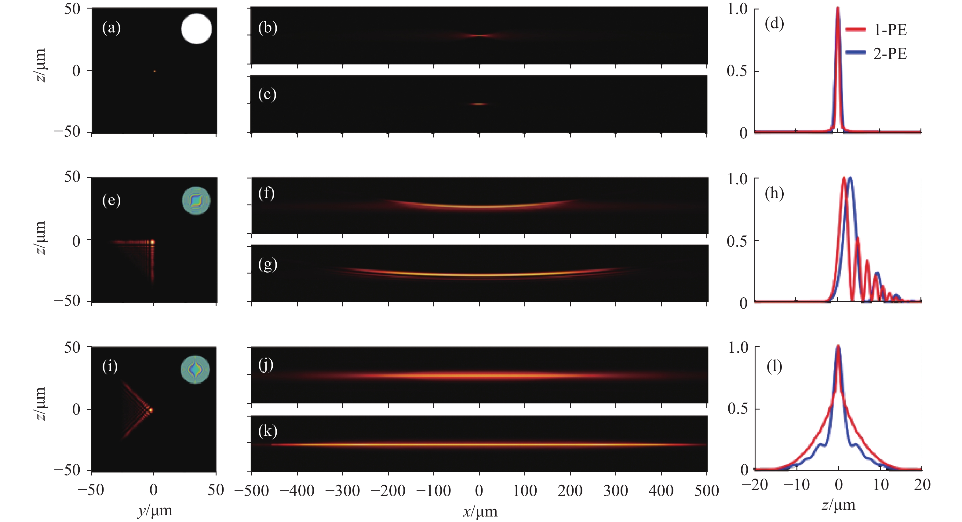
2020年,Neveen A. Hosny等人[8]提出了平板艾里光片的概念。图1为高斯光束、艾里光束与平板艾里光束在静止与扫描时不同方向的轮廓。光片显微镜通常以高斯光束为照明光束,高斯光束在束腰处最细(图1(a)),成像的分辨率最高,但在束腰两侧,光束迅速发散,轴向分辨率变差,如图1(b)所示,在单光子(one-photon excitation, 1-PE)激发条件下,高斯光束的成像视场较小。双光子激发(图1(c))对高斯光束成像的影响较小。图1(d)展示了在x = 0时,不同条件下高斯光束在z向的强度分布,可以看出双光子激发的高斯光束与单光子高斯光束的轴向分辨率相差不大。相较于以普通光片显微镜而言,艾里光片显微镜将艾里光束作为照明光束,能够大大提升显微镜的成像视场。图1(e)展示了静态艾里光束的y-z截面,右上角是加载在空间光调制器上的立方相位图。图1(f)是单光子激发的艾里光片的x-z截面,可以明显看到成像视场的增大,但由于艾里光束旁瓣的存在,在成像后需要进行图像反卷积处理,才能够获得较好的轴向分辨率。而且,由于艾里光片的自弯曲特性,成像会出现一定的失真及伪影。而双光子激发的艾里光片(图1(g))能够一定程度上减少旁瓣的存在,但是,剩余的旁瓣和光片的自弯曲仍然会导致成像伪影和失真。图1(h)展示了在x = 0时,单双光子激发的艾里光束在z向的强度分布,可以看出双光子激发的艾里光束会产生一定的轴向偏移。双光子激发的艾里光片主瓣的半峰宽较大,说明双光子激发会降低艾里光片显微镜的轴向分辨率,但双光子激发的艾里光片的旁瓣数量确实有所降低。笔者将普通艾里光束的三次相位图像旋转45°,从而产生一个y-z面旋转的艾里光束(图1(i)),之后经过y方向的扫描,生成平板艾里光片,该光片的旁瓣不明显而且两侧对称(图1(j))。双光子激发后,旁瓣的能量更进一步的降低(图1(k)),几乎可以视为没有旁瓣。最终的成像结果 可以免除反卷积处理这一步骤。通过图1(l)可以验证,双光子平板艾里光片显微镜的轴向分辨率比单光子更高。因此,文中实验采用双光子激发以验证平板艾里光片显微镜相较于普通艾里光片显微镜的成像优势。
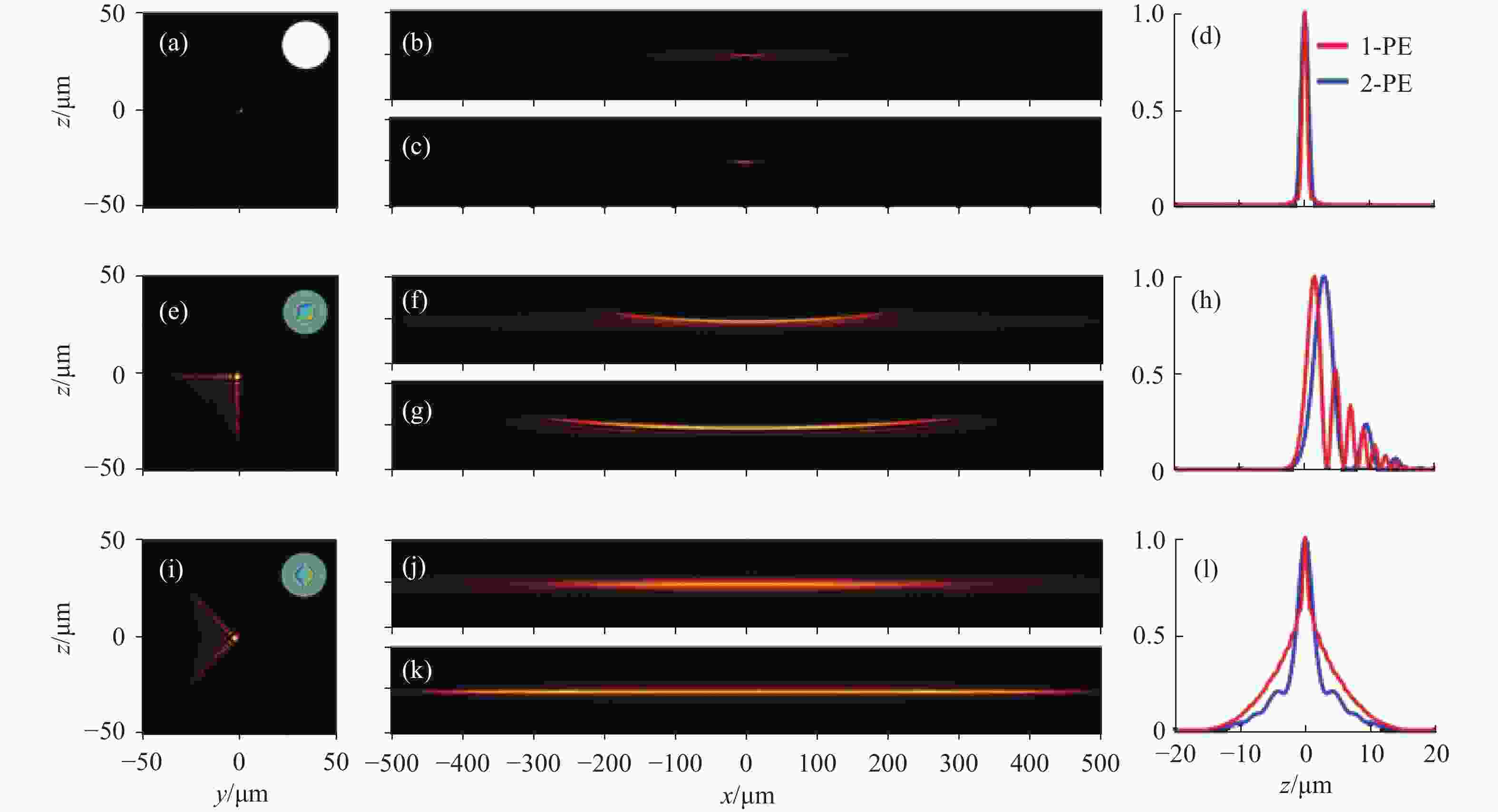
图 1 高斯光束、艾里光束与平板艾里光束在静止与扫描时不同方向的轮廓及强度分布。(a) 静态高斯光束在束腰(x = 0)处,y-z截面轮廓图;(b)沿y轴扫描的高斯光片,单光子激发的x-z截面轮廓;(c)双光子激发的高斯光片x-z截面轮廓;(d) x=0处,单光子和双光子激发的高斯光片z向强度分布;(e)~(h) 艾里光束在静止与扫描之后在不同方向的轮廓及强度分布图;(i)~(l) 平板艾里光束在静止与扫描之后在不同方向的轮廓及强度分布图
Figure 1. Profiles and intensity distributions of Gaussian beams, Airy beams, and planar-Airy beams in different directions at static and scanning. (a) The y-z cross-section profile of static Gaussian beam at the beam waist (x=0); (b) The x-z cross-section profile of one-photon excited, Gaussian light-sheet scanned along the y-axis; (c) The x-z cross-section profile of Gaussian light-sheet excited by two-photon; (d) The z-direction intensity distribution of the Gaussian light-sheet excited by one-photon and two-photon at x = 0; (e)-(h) The profile and intensity distribution of Airy beam in different directions at static and after scanning; (i)-(l) The profile and intensity distribution of planar-Airy beam in different directions at static and after scanning
-
光片显微镜的基本结构如图2(a)所示,激发光源采用飞秒激光器(Spectra-Physics, InSight ® X3™, 680~ 1300 nm),飞秒激光的脉宽小于120 fs,能够实现双光子激发。激光器发出的激光经过半波片调节光强,之后再经过偏振分束器(PBS)和第二个半波片将光束调制为偏振光。经过透镜组L1(f =50 mm)和L2(f = 250 mm)进行扩束,在此 4f 系统的傅里叶平面上放置口径为100 μm的针孔滤波器(Pinhole)以滤除散射光,从而提升光束质量。
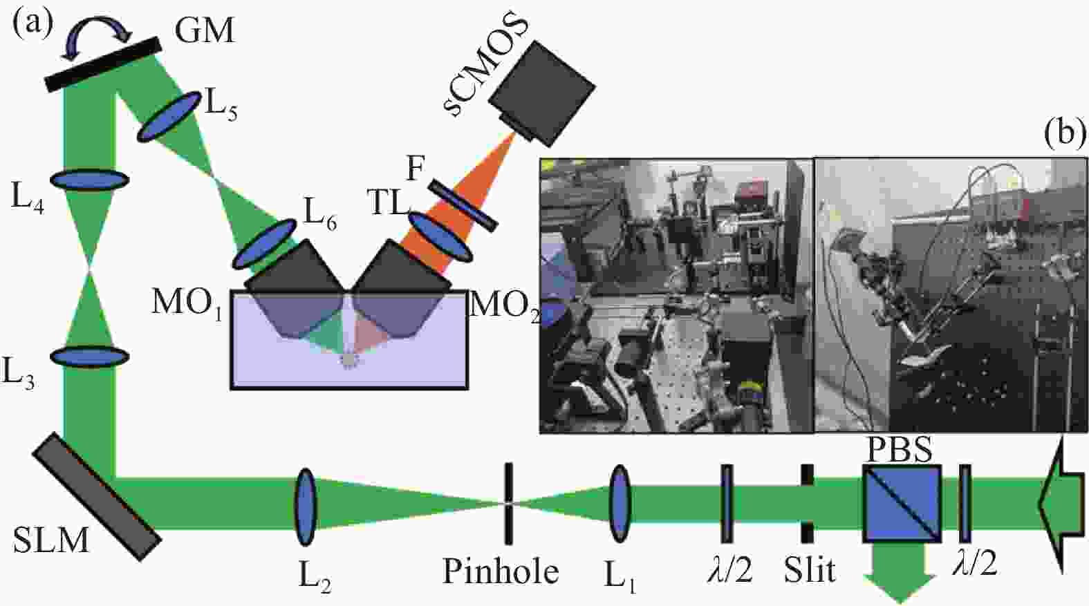
图 2 (a) 光片荧光显微镜光路图;λ/2: 半波片;PBS:偏振分束器;Slit:狭缝;L:透镜;Pinhole:针孔滤波器;SLM:空间光调制器;GM:扫描振镜;MO:物镜;TL:筒镜;F:滤波片;(b) 光片荧光显微镜实验装置图
Figure 2. (a) Optical diagram of light-sheet fluorescence microscope; λ/2: half-wave plate; PBS: polarization beam splitter; Slit: slit; L: lens; Pinhole: pinhole filter; SLM: spatial light modulator; GM: galvo mirror; MO: microscope objective; TL: tube lens; F: filters; (b) Experimental setup of light-sheet fluorescence microscope
之后将特定方向的偏振光束引入到空间光调制器(SLM, Thorlabs, EXULUS-4 K1/M, 400~850 nm)上进行相位调制[9-10]。在实验中,笔者利用空间光调制器加载不同的相位图,以生成不同的光束,如高斯光束、艾里光束和平板艾里光束等。调制后的光束经过通过由L3(f = 45 mm)和L4(f = 75 mm)透镜组继续进行扩束,之后到达扫描振镜(GM, Thorlabs, GVS011, 400 nm~2 μm),扫描振镜所在的位置与激发物镜 (MO1, Nikon, CFI Plan Flour 10×) 的入瞳共轭。透镜组L5(f = 50 mm)和L6(f = 100 mm)将光束放大到12.2 mm从而完全覆盖激发物镜的入瞳,L5和L6透镜组也与扫描振镜组成了f-theta扫描透镜,可以通过信号发生器控制扫描透镜的扫描频率及振幅等参数[11],使光束沿y轴进行扫描以产生光片。扫描频率一般取200~300 Hz,振幅大小受实验条件的改变而改变,以满足不同的激发需求。
样本池中的样本受照明光片的激发,产生荧光。探测物镜 (MO2, Nikon, CFI Plan Flour 10×) 与筒镜能够(TL, f = 200 mm)结合能够收集焦平面上的荧光信号,并聚焦成像在sCMOS相机(Hamamatsu, C11440-42U30) 上。在成像的过程中,根据激发波长的不同还需要更换不同的滤波片[12](F, Thorlabs, FKSP01&01-IR) 以满足成像需要。样本的自动化控制依赖于三维位移台(thorlabs, RBL13D/M,行程为13 mm)与步进电机驱动器(thorlabs, ZST213B)的结合。将样本固定到样本池内,对焦后,可以实现x-y面的成像。使用开源软件Micromanger可以实现sCMOS相机与三维位移台的联动,实现光片对样本的z向扫描成像。根据样本的特性,可以选取不同的曝光时间和扫描步长。曝光时间一般选取100 ms,扫描步长选取1 μm。
实际搭建的光学系统如图2(b)所示。光片显微镜的横向分辨率与轴向分辨率互不影响,横向分辨率由检测物镜的数值孔径(Numerical Aperture, NA)大小决定。研究所用的激发物镜NA为0.27,探测物镜NA为0.3,理论上能够获得的横向分辨率公式为:
$$ {R}_{T}=\frac{0.61{\lambda }_{\rm em}}{{NA}_{\rm det}} $$ (1) 式中:λem为发射波长;NAdet检测物镜的数值孔径。假设发射波长为950 nm时,横向分辨率为1.93 μm。
光片显微镜的轴向分辨率受光片厚度和检测物镜的景深影响。而增大激发物镜的实际数值孔径,能够使高斯光束的束腰变得更细,从而获得高轴向分辨率。当光片厚度小于检测物镜景深时,轴向分辨率由光片厚度决定,即由照明物镜NA决定。反之,则由检测物镜景深决定。检测物镜的景深计算公式为:
$$ DOF=\frac{4n{\lambda }_{\rm em}}{{NA}_{\rm det}^{2}} $$ (2) 式中:n为介质的折射率,这里取水的折射率1.33。假设发射波长为500 nm时,成像系统的景深为29.56 μm。在研究中,探测物镜对成像系统的轴向分辨率没有制约,成像系统的轴向分辨率由光片厚度决定。通过控制激发物镜的实际数值孔径可以改变系统的轴向分辨率。
-
成像系统的点扩散函数(point spread function,PSF)测量是必不可少的,通常估量点扩散函数的方式有两种:数值计算和物理测量。物理测量通常使用荧光微球检测的方法,原理是对纳米尺寸的荧光微球成像,得到显微物镜聚焦平面的荧光微球强度分布函数。荧光微球的直径足够小,可以将其近似为系统的点扩散函数PSF。因此,文中利用荧光微球(QDSphere, QDSF21001; Mean diameter:1.1 μm)对成像系统进行校正。
使用1.5%的琼脂糖包埋荧光微球,之后用Fep (Fluorinated Ethylene Propylene) 管装载琼脂糖,Fep管规格为内径2 mm,外径3 mm。
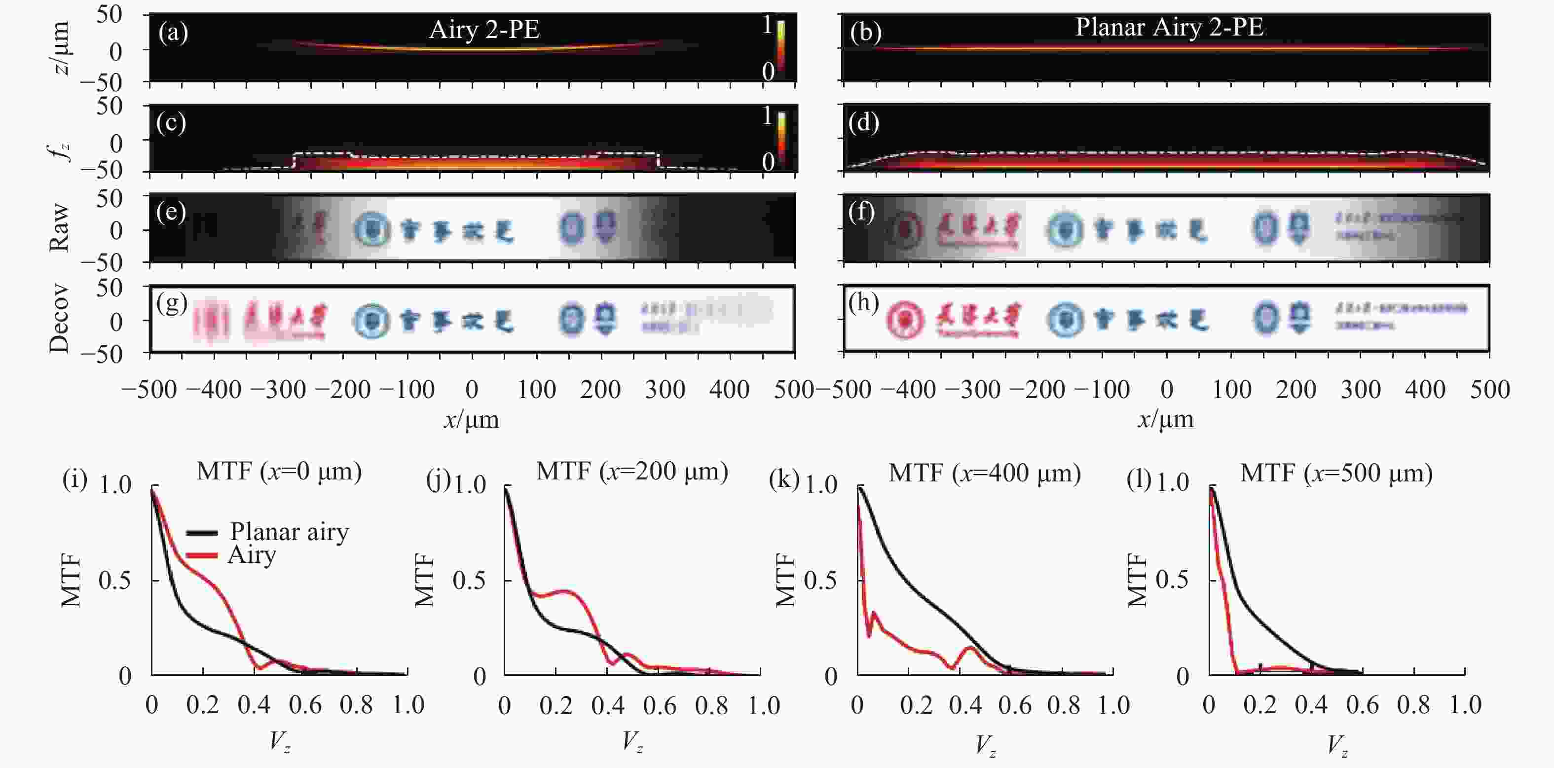
图 3 双光子激发下,艾里光片和平板艾里光片的数值计算结果。(a)、(b) 艾里光片和平板艾里光片的x-z截面轮廓;(c)、(d) 艾里光片和平板艾里光片沿x轴的MTF分布;(e)、(f) 仿真成像结果;(g)、(h) 反卷积处理之后的结果;(i)、(l) 在不同传播位置(x = 0、200、400、500 μm),普通艾里光片与平板艾里光片的MTF分布情况
Figure 3. Numercial calculation results of Airy light-sheet and planar-Airy light-sheet under 2-PE. (a), (b) The x-z cross-section profile of Airy light-sheet and planar-Airy light-sheet; (c), (d) MTF distribution along the x-axis for Airy light-sheet and planar-Airy light-sheet; (e), (f) Simulation imaging results; (g), (h) Result after deconvolution processing; (i), (l) MTF distribution of Airy light-sheet and planar-Airy light-sheet at different propagation positions (x = 0, 200, 400, 500 μm)
-
对成像系统进行校正后,利用其探究了自发性脑出血斑马鱼模型的脑血管的发育和破裂现象。文中利用阿托伐他汀(ATV)诱导斑马鱼脑出血,进行生物造模。研究采用斑马鱼转基因品系为:Tg(flk: EGFP)标记斑马鱼血管内皮细胞,Tg(gata1: Dsred)标记斑马鱼红细胞。将琼脂糖溶液与麻醉的斑马鱼胚胎混合,并置于Fep管中。待琼脂糖凝固后起到固定作用,后将Fep管置于样本池中,为成像实验做准备。
-
文中在2-PE情况下对普通艾里光片与平面艾里光片进行了数值计算,结果如图3所示。图3(a)、(b)展示了两种光束在传播方向上的光片轮廓,普通艾里光束由于探测物镜的景深限制,超出景深之外的部分难以被收集;而平板艾里光束是平坦的,不会产生超出景深之外的部分,因此,平板艾里光束的成像视场相较于普通艾里光片的视场增大。图3(c)、(d)是z向的调制传递函数(MTF)分布,普通艾里光片在x =±300 μm时MTF骤降,超出此范围的部分便超出了显微镜的视场。平板艾里光片在x=±450 μm内都能维 持较高的MTF,表示平板艾里光片显微镜的成像视场在理论上能够达到900 μm。图3(e)、(f)为艾里光片显微镜和平板艾里光片显微镜的仿真成像结果。图3(g)、(h)为成像结果经反卷积处理之后的图像。从图3(e)~(h)中可以看出普通艾里光片显微镜的成像结果很模糊并且有图像畸变,必须经过图像处理才能够得到清晰的图像。而平板艾里光片显微镜则能够得到较为清晰的原始图像(图3(f)),经过图像处理之后(图3(h))效果更好。对比图3(e)~(h)可以得到,平板艾里光片显微镜明显能够得到较大成像视场(~ 900 μm)。图3(i)~(l)分别展示了在x= 0、200、400、500 μm处,普通艾里光片和平板艾里光片显微镜的MTF分布图像,MTF代表了光学系统传递信息的能力。在靠近光片中心的位置(图3(i)),黑色线整体低于红色线,说明平板艾里光片传递信息的能力不如普通艾里光片显微镜。但在接近视场边缘的位置,平板艾里光片显微镜依然可以传递较多的低频信息,如图3(l)所示,在x = 500 μm处,艾里光片显微镜几乎不能传递频率超过0.1的低频信息,平板艾里光片显微镜依然能够传递频率在0~0.4之间的低频信号,可以验证平板艾里光片显微镜的成像视场增大。
-
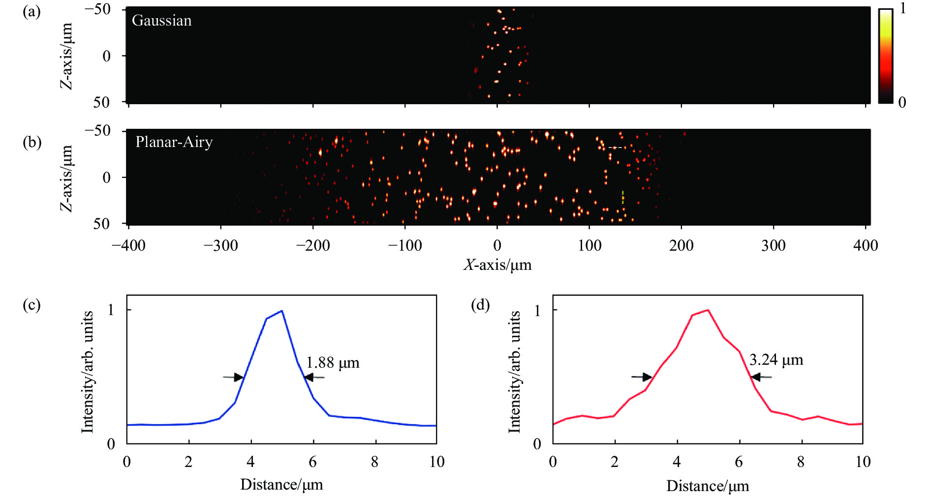
在实验台搭建完成后,进行荧光小球校正实验。设置激发波长为920 nm,选取800 nm和700 nm的短通滤波片。如图4所示,普通光片显微镜和平板艾里光片显微镜的成像结果具有较大差异。普通艾里光片显微镜以高斯光束为激发光束,成像视场在100 μm以内,但以平板艾里光束为激发光束,笔者可以得较长(500 μm)的荧光微球成像视场。而且,双光子激发还可以免去后处理步骤,大大提高了成像的效率。
图4(c)为平板艾里光片显微镜成像结果的横向强度分布,对应于图4(b)中的白色虚线,其半峰宽为1.88 μm,统计成像视场内的多个荧光微球的横向强度分布,最终得到平板艾里光片显微镜的横向分辨率为(1.93±0.17) μm,与理论值近似。图4(d)为平板艾里光片显微镜成像荧光微球的轴向强度分布,对应于图4(b)中的黄色虚线,其半峰宽为3.24 μm,统计成像视场内的多个荧光微球的轴向强度分布,最终得到平板艾里光片显微镜的轴向分辨率为(3.19±0.41) μm。

图 4 双光子激发下,高斯光片和平板艾里光片显微镜的成像结果。(a)普通光片显微镜在双光子激发下的成像结果;(b)平板艾里光片显微镜在双光子激发下的成像结果;(c)强度分布图示,对应于图(b)的白色虚线;(d)强度分布图示,对应于图(b)的黄色虚线
Figure 4. Imaging results of Gaussian and planar-Airy light-sheet microscope under 2-PE. (a) Imaging results of ordinary light-sheet microscopy under 2-PE; (b) Imaging results of planar-Airy light-sheet microscopy under 2-PE; (c) Graphical representation of the intensity distribution, corresponding to the white dotted line of figure (b); (d) Graphical representation of the intensity distribution, corresponding to the yellow dotted line of figure (b)
-
文中对斑马鱼脑出血情况进行了实时监测。在2-PE模式下,以920 nm的照明波长激发绿色荧光蛋白(EGFP),以730 nm的波长激发红色荧光蛋白(Dsred)。在探测光路上使用650 nm和700 nm短通滤波片,以消除激发光及其他光源的干扰。在双通道成像时发现,切换波长会导致光片产生一定的偏移,影响最终成像的质量。为了消除不同激发波长切换对成像实验的不利影响,可以通过在平板艾里光片的调制相位上叠加菲涅耳相位以补偿。可以得到斑马鱼大脑x×y×z=0.60 mm×0.60 mm×0.40 mm/60 s的时间分辨率成像,将双通道成像结果组合,如图5(a)所示。笔者不仅可以对斑马鱼脑部进行快速大体积成像,而且能够实时观测斑马鱼脑部血管的发育情况。如图5(b)~(e)所示,对应于图(a)黄框内的局部血管,在44.5~46.5 hpf(hours post fertilization)的时间段内,斑马鱼大脑局部有脑血管的发育,将两条未连接的血管串联在一起。

图 5 (a) 斑马鱼脑血管的双通道单次三维成像结果; (b) 44.5~46.5 hpf时间段内局部脑血管的生长图像
Figure 5. (a) Two-channel single-shot 3D imaging results of zebrafish intracerebral vessels; (b) Images of local cerebrovascular growth during the 44.5-46.5 hpf
在接下来的时间内,这条刚刚发育出的血管却发生了破裂。图6展示了这条血管在54 hpf时的碎裂情况。图6(a)中左边一列图展示了在碎裂处(黄框)的血管单通道成像结果(47.5~54 hpf),可以明显看出血管细胞的游离及消失。右边一列图展示了在51~54 hpf时间内的双通道成像结果,可以明显看出表达Dsred细胞在破裂处溢出并大量聚集,侧面验证了脑血管的破裂现象。
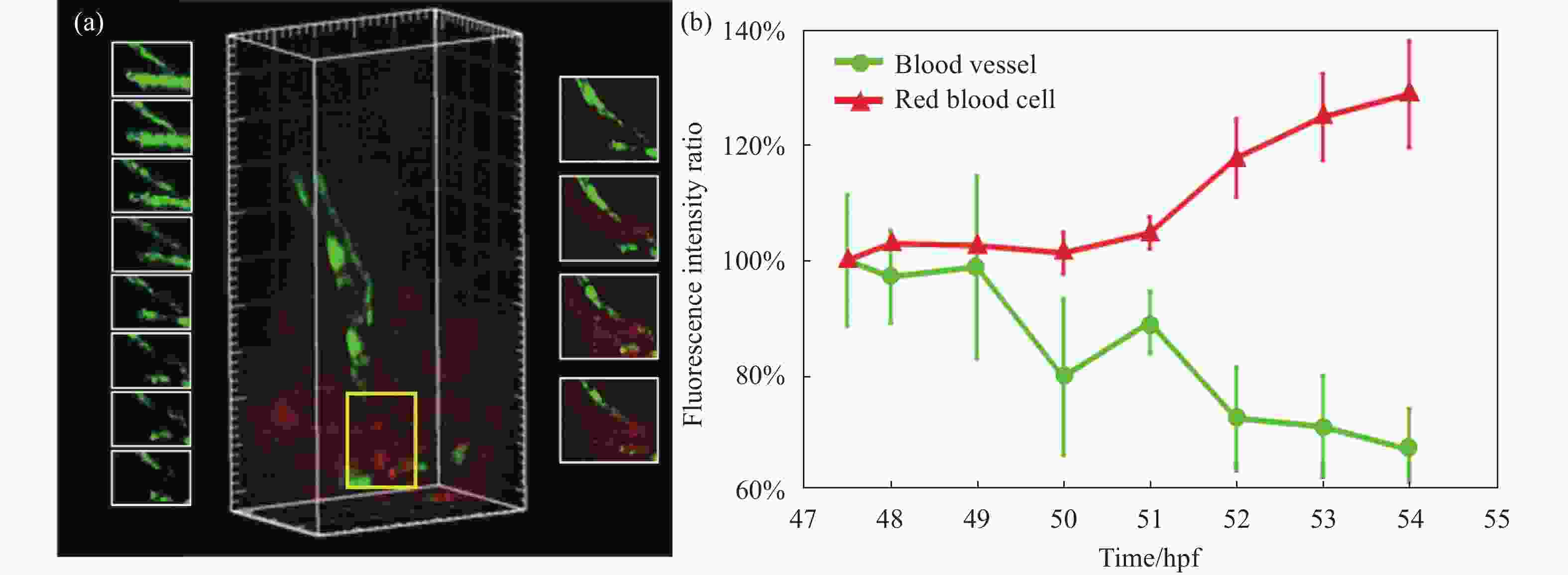
图 6 出血脑血管及红细胞荧光强度随时间的变化分析。(a)黄框中血管和红细胞荧光强度变化示意图(47.5~54 hpf);(b)不同时间点下血管和红细胞的荧光强度比变化曲线
Figure 6. Analysis of the changes of fluorescence intensity of hemorrhagic intracerebral blood vessels and red blood cells with time. (a) Schematic diagram of the changes in the fluorescence intensity of blood vessels and red blood cells in the yellow box (47.5-54 hpf); (b) Fluorescence intensity ratio curves of blood vessels and red blood cells at different time points
文中还统计了血管破裂位置荧光强度的变化(见图6(b))。为了定量表示斑马鱼脑血管破裂与荧光强度之间的关系,可以统计斑马鱼出血部位的荧光强度变化,并以斑马鱼未发生出血时的脑血管和红细胞的荧光强度为初始值Ic,此后各个时间点内观察到的荧光信号强度为If,计算q=If / Ic。q值代表了脑血管破裂时相较于正常情况下,血管荧光的减小和红细胞荧光的增加。除了上述发现的血管出血区域,笔者还找到斑马鱼脑出血的其他部位,将多个出血区域作为量化强度变化的样本,绘制出斑马鱼脑血管荧光强度和血细胞荧光强度与脑出血之间的关系图。图6(b)量化了不同时间点下血管荧光与红细胞荧光q值的变化,可以明显看出脑血管的荧光比值逐渐降低,说明了脑血管结构逐渐被破坏,表达EGFP荧光的细胞数量逐渐减少。而红细胞荧光比值逐渐增高,在51 hpf迅速增大,说明51 hpf后血管破裂较为明显,表达Dsred的细胞在破裂处溢出并大量聚集,也能从侧面验证脑血管的破裂现象。
-
文中阐述了光片显微镜的基本成像结构,并比较了普通艾里光片显微镜与平板艾里光片显微镜的不同点。利用Matlab进行光片仿真,并对成像系统的点扩散函数、调制传递函数进行了分析,理论验证了双光子激发条件下平板艾里光片显微镜的成像视场大(900 μm×900 μm),无需图像后处理的优点。然后利用荧光微球实验和生物实验进一步展现出平板艾里光片显微镜大视场成像的优点。实验证明,平板艾里光片显微镜能够对斑马鱼模型实现0.60 mm
$ \times $ 0.60 mm$ \times $ 0.40 mm的单次成像体积。平板艾里光片显微镜能够实现一些疾病模型,如斑马鱼脑出血的实时监测分析,有希望在将来的研究中,通过标记不同的生物标志物,探究出更多的脑血管破裂的相关机制及规律,也可应用于脑出血药物的精准筛选,为人类脑出血疾病的预后治疗做出更大贡献。
Research on field-enhanced planar-Airy light-sheet microscopy (invited)
-
摘要: 光片显微镜是近些年来研究较多的生物成像技术,相较于传统的激光共聚焦扫描显微镜而言,光片显微镜能够实现快速、低光毒性的体积成像。光片显微镜的照明光束可以选择高斯光束或其他无衍射光束(如贝塞尔光束、艾里光束等)。艾里光片显微镜是目前研究较多的技术,但是普通的艾里光片显微镜存在一个较大的问题,艾里光束具有自弯曲的特性,导致艾里光片在视场的两端超出探测物镜的景深范围,无法发挥出最优的成像效果。将艾里光束旋转45°形成平板艾里光片,使艾里光片不超出探测物镜的景深,以增大光片显微镜的成像视场。并利用双光子荧光激发技术,免除图像的后处理过程,大大提高了成像的效率。利用Matlab进行光学仿真,得到平板艾里光片显微镜的成像视场(~900 μm)比普通艾里光片显微镜的成像视场(~600 μm)增加了50% 。搭建的平板艾里光片显微镜利用荧光微球进行校正实验,得到成像系统的横向分辨率为(1.93±0.17) μm,轴向分辨率为(3.19±0.41) μm。对斑马鱼脑出血模型的实时观测中,可以得到时间分辨率为x×y×z = 0.60 mm×0.60 mm×0.40 mm/60 s 的成像结果,并可以对局部血管的生长和发育进行实时监测,有利于脑出血疾病的机制探究。Abstract: Light-sheet microscopy is a biological imaging technology that has been studied a lot in recent years. Compared with traditional confocal laser scanning microscopy, light-sheet microscopy can achieve rapid volume imaging with low phototoxicity. The illumination beam of light-sheet microscope can choose Gaussian beam or other non-diffracting beams (such as Bessel beam, Airy beam, etc.). Airy light-sheet microscopy is the most researched technology at present, but there is a big problem with ordinary Airy light-sheet microscopy. Airy beam has the characteristic of self-bending, which causes Airy beam to exceed detection at both ends of the field of view. The depth of field of the objective lens cannot produce the best imaging effect. The Airy beam was rotated by 45° to form a planar-Airy light-sheet, so that the Airy light-sheet did not exceed the depth of field of the detection objective, so as to increase the imaging field of view of the light-sheet microscope. And using two-photon fluorescence excitation technology, the post-processing process of the image was eliminated, greatly improving the efficiency of imaging. In this study, Matlab was used for optical simulation, and the imaging field of view (~900 μm) of the planar-Airy light-sheet microscope was increased by 50% compared with the imaging field of view (~600 μm) of the ordinary Airy light-sheet microscope. The constructed planar-Airy light-sheet microscope was calibrated with fluorescent microspheres, and the lateral resolution of the imaging system was (1.93±0.17) μm and the axial resolution was (3.19±0.41) μm. In the real-time observation of the zebrafish intracerebral hemorrhage model, imaging results with a temporal resolution of x
$ \times $ y$ \times $ z = 0.60 mm$ \times $ 0.60 mm$ \times $ 0.40 mm/60 s can be obtained, and the growth and development of local blood vessels can be monitored in real-time to explore the mechanism of cerebral hemorrhage disease. -
图 1 高斯光束、艾里光束与平板艾里光束在静止与扫描时不同方向的轮廓及强度分布。(a) 静态高斯光束在束腰(x = 0)处,y-z截面轮廓图;(b)沿y轴扫描的高斯光片,单光子激发的x-z截面轮廓;(c)双光子激发的高斯光片x-z截面轮廓;(d) x=0处,单光子和双光子激发的高斯光片z向强度分布;(e)~(h) 艾里光束在静止与扫描之后在不同方向的轮廓及强度分布图;(i)~(l) 平板艾里光束在静止与扫描之后在不同方向的轮廓及强度分布图
Figure 1. Profiles and intensity distributions of Gaussian beams, Airy beams, and planar-Airy beams in different directions at static and scanning. (a) The y-z cross-section profile of static Gaussian beam at the beam waist (x=0); (b) The x-z cross-section profile of one-photon excited, Gaussian light-sheet scanned along the y-axis; (c) The x-z cross-section profile of Gaussian light-sheet excited by two-photon; (d) The z-direction intensity distribution of the Gaussian light-sheet excited by one-photon and two-photon at x = 0; (e)-(h) The profile and intensity distribution of Airy beam in different directions at static and after scanning; (i)-(l) The profile and intensity distribution of planar-Airy beam in different directions at static and after scanning
图 2 (a) 光片荧光显微镜光路图;λ/2: 半波片;PBS:偏振分束器;Slit:狭缝;L:透镜;Pinhole:针孔滤波器;SLM:空间光调制器;GM:扫描振镜;MO:物镜;TL:筒镜;F:滤波片;(b) 光片荧光显微镜实验装置图
Figure 2. (a) Optical diagram of light-sheet fluorescence microscope; λ/2: half-wave plate; PBS: polarization beam splitter; Slit: slit; L: lens; Pinhole: pinhole filter; SLM: spatial light modulator; GM: galvo mirror; MO: microscope objective; TL: tube lens; F: filters; (b) Experimental setup of light-sheet fluorescence microscope
图 3 双光子激发下,艾里光片和平板艾里光片的数值计算结果。(a)、(b) 艾里光片和平板艾里光片的x-z截面轮廓;(c)、(d) 艾里光片和平板艾里光片沿x轴的MTF分布;(e)、(f) 仿真成像结果;(g)、(h) 反卷积处理之后的结果;(i)、(l) 在不同传播位置(x = 0、200、400、500 μm),普通艾里光片与平板艾里光片的MTF分布情况
Figure 3. Numercial calculation results of Airy light-sheet and planar-Airy light-sheet under 2-PE. (a), (b) The x-z cross-section profile of Airy light-sheet and planar-Airy light-sheet; (c), (d) MTF distribution along the x-axis for Airy light-sheet and planar-Airy light-sheet; (e), (f) Simulation imaging results; (g), (h) Result after deconvolution processing; (i), (l) MTF distribution of Airy light-sheet and planar-Airy light-sheet at different propagation positions (x = 0, 200, 400, 500 μm)
图 4 双光子激发下,高斯光片和平板艾里光片显微镜的成像结果。(a)普通光片显微镜在双光子激发下的成像结果;(b)平板艾里光片显微镜在双光子激发下的成像结果;(c)强度分布图示,对应于图(b)的白色虚线;(d)强度分布图示,对应于图(b)的黄色虚线
Figure 4. Imaging results of Gaussian and planar-Airy light-sheet microscope under 2-PE. (a) Imaging results of ordinary light-sheet microscopy under 2-PE; (b) Imaging results of planar-Airy light-sheet microscopy under 2-PE; (c) Graphical representation of the intensity distribution, corresponding to the white dotted line of figure (b); (d) Graphical representation of the intensity distribution, corresponding to the yellow dotted line of figure (b)
图 5 (a) 斑马鱼脑血管的双通道单次三维成像结果; (b) 44.5~46.5 hpf时间段内局部脑血管的生长图像
Figure 5. (a) Two-channel single-shot 3D imaging results of zebrafish intracerebral vessels; (b) Images of local cerebrovascular growth during the 44.5-46.5 hpf
图 6 出血脑血管及红细胞荧光强度随时间的变化分析。(a)黄框中血管和红细胞荧光强度变化示意图(47.5~54 hpf);(b)不同时间点下血管和红细胞的荧光强度比变化曲线
Figure 6. Analysis of the changes of fluorescence intensity of hemorrhagic intracerebral blood vessels and red blood cells with time. (a) Schematic diagram of the changes in the fluorescence intensity of blood vessels and red blood cells in the yellow box (47.5-54 hpf); (b) Fluorescence intensity ratio curves of blood vessels and red blood cells at different time points
-
[1] Durnin J. Exact solutions for nondiffracting beams. I. The scalar theory [J]. J Opt Soc, 1987, 4(4): 651-654. doi: 10.1364/JOSAA.4.000651 [2] Berry M V. Nonspreading wave packets [J]. American Journal of Physics, 1998, 47(3): 264-267. doi: 10.1119/1.11855 [3] Siviloglou G A, Chrlstodoulides D N. Accelerating finite energy Airy beams [J]. Optics Letters, 2007, 32(8): 979-981. doi: 10.1364/ol.32.000979 [4] Siviloglou G A, Broky J, Dogariu A, et al. Observation of accelerating airy beams [J]. Physical Review Letters, 2007, 99(21): 213901. doi: 10.1103/PhysRevLett.99.213901 [5] Vettenburg T, Dalgarno H I C, Nylk J, et al. Light-sheet microscopy using an Airy beam [J]. Nature Methods, 2014, 11(5): 541-544. doi: 10.1038/nmeth.2922 [6] Ying Yachen, Zhang Guangjie, Jia Huilin, et al. Multi-photon skin tissue imaging technology and its applications [J]. Chinese Optics, 2019, 12(1): 104-111. (in Chinese) doi: 10.3788/CO.20191201.0104 [7] Su Yahui, Qin Tiantian, Xu Bing, et al. Patterned microlens processed using two-photon polymerization of femtosecond laser and its imaging test [J]. Optics and Precision Engineering, 2020, 28(12): 2629-2635. (in Chinese) doi: 10.37188/OPE.20202812.2629 [8] Hosny N A, Seyforth J A , Spickermann G, et al. A planar airy beam light-sheet for two-photon microscopy [J]. Biomedical Optics Express, 2020, 11(7): 3927-3935. doi: 10.1364/BOE.395547 [9] Fu Yanjun, Han Yonghua, Chen Yuan, et al. Research progress of 3D measurement technology based on phase coding [J]. Infrared and Laser Engineering, 2020, 49(3): 20200301. (in Chinese) doi: 10.3788/IRLA202049.0303010 [10] Yang Jingyu, Ren Zhijun, Huang Wenjun, et al. Complex non-diffraction beams generated using binary computational holography [J]. Chinese Optics, 2022, 15(1): 14-21. (in Chinese) doi: 10.37188/CO.2021-0061 [11] Xu Baoteng, Yang Xibin, Liu Jialin, et al. Image correction for high speed scanning confocal laser endomicroscopy [J]. Optics and Precision Engineering, 2020, 28(1): 60-67. (in Chinese) doi: 10.3788/OPE.20202801.0060 [12] Du Jianxiang, Zong Xiaoying, Luo Shikui, et al. Plane wave transmitted wavefront simulation and measurement of filter with multi-spectrum [J]. Infrared and Laser Engineering, 2021, 50(9): 20210923. (in Chinese) doi: 10.3788/IRLA20200528 -

 点击查看大图
计量
- 文章访问数: 233
- HTML全文浏览量: 45
- PDF下载量: 71
- 被引次数: 0


