


 下载:
下载:


-
随着数字技术的快速发展,光学三维测量因其非接触、精度高、分辨率高、视场大等优势在工业设计、智能制造、医学整形、农产品检测、数字影像等方面有了广泛的研究和应用[1-6]。结构光测量方法[7-8]作为光学三维测量方法中最常用的一种方法,研究内容主要分为单帧投影三维测量和多帧投影三维测量两大类[9]。多帧结构光测量主要以相移算法(PMP)[10]为代表,投影N帧(N≥3)正弦光栅至被测物体表面,精确的相位信息能够通过相机(CCD)采集的受物体面形调制的N帧变形条纹图计算提取,经相位展开和相位-高度映射而获得物体三维面形信息,其测量精度随着正弦光栅相移步数增加而提高,但测量速度因相移步数增加而相对较慢,难以适应运动物体的实时或在线测量,因此,以单帧结构光投影的实时三维测量方法备受人们关注。单帧三维物体测量主要分为投影单帧正弦光栅和投影单帧正交调制复合光栅[9]等方式。单帧正弦光栅投影以Takeda等人提出的傅里叶变换轮廓术(FTP)[11]为代表,只需投影一帧正弦光栅,经傅里叶变换后在频率内提取包含物体面形信息的基频成分,经逆傅里叶变换得到空域内的物体相位信息。其测量速度快,适合动态目标测量,但由于频域滤波行为,其测量精度相对PMP较低。由Guan C等人[12]提出的复合结构光的测量方法基于频分复用的原理将PMP的N帧正弦光栅通过与其相移方向正交的N个不同载频相乘组合成一幅复合光栅(OCG),此方法有效地结合了PMP的测量精度高和单帧FTP测量速度快的优点。He Yuhang等人[13-15]在此基础上通过投影参数校正、背景光和对比度校正等方法,He, D. W等人[16]对相移条纹周期优化,都较大程度地提高了正交复合光栅的测量精度。然而,目前研究的复合光栅投影方法仍然存在一个共同的问题,受商用DLP标准限制[17],被调制的多帧光栅像共享256灰阶动态范围,不可避免地使解调的变形条纹图的动态范围相对较小,被测物体面形相位信息被压缩,使相位极点相对增多而出现展开相位断裂现象甚至无法展开,因此文中提出了一种基于灰度拓展复合光栅(OCGGE)的单帧三维测量方法,首先设计一期望具有766灰阶的正交复合光栅,采用时分复用原理[18],将设计的复合光栅按照最小差值方法拆分为三幅不同的具有256灰阶的复合条纹图,并以此三幅复合条纹图编辑成一重复播放的视频,将该视频投射到待测物体表面,设置10 bit CCD的曝光时间为3倍视频刷新周期的整数倍,就可采集到具有766灰阶动态范围的变形复合光栅像,提高解调正弦相移条纹图的对比度和动态范围,从而丰富重构物体面形细节信息,减少极点数量,有效提高测量精度。
-
PMP相移测量轮廓术具有像素级的测量精度,并且对环境光与物体反射率变化有很强的鲁棒性,但是由于需要投射多幅图像以计算物体相位信息需要花费较多的时间,因此这种方法对物体实时三维形貌测量误差较大[19]。Guan C等人[12]提出的复合光栅投影方法将N幅相移光栅与不同频率的正弦光栅正交相乘后组合得到一帧复合光栅像,如图1所示。
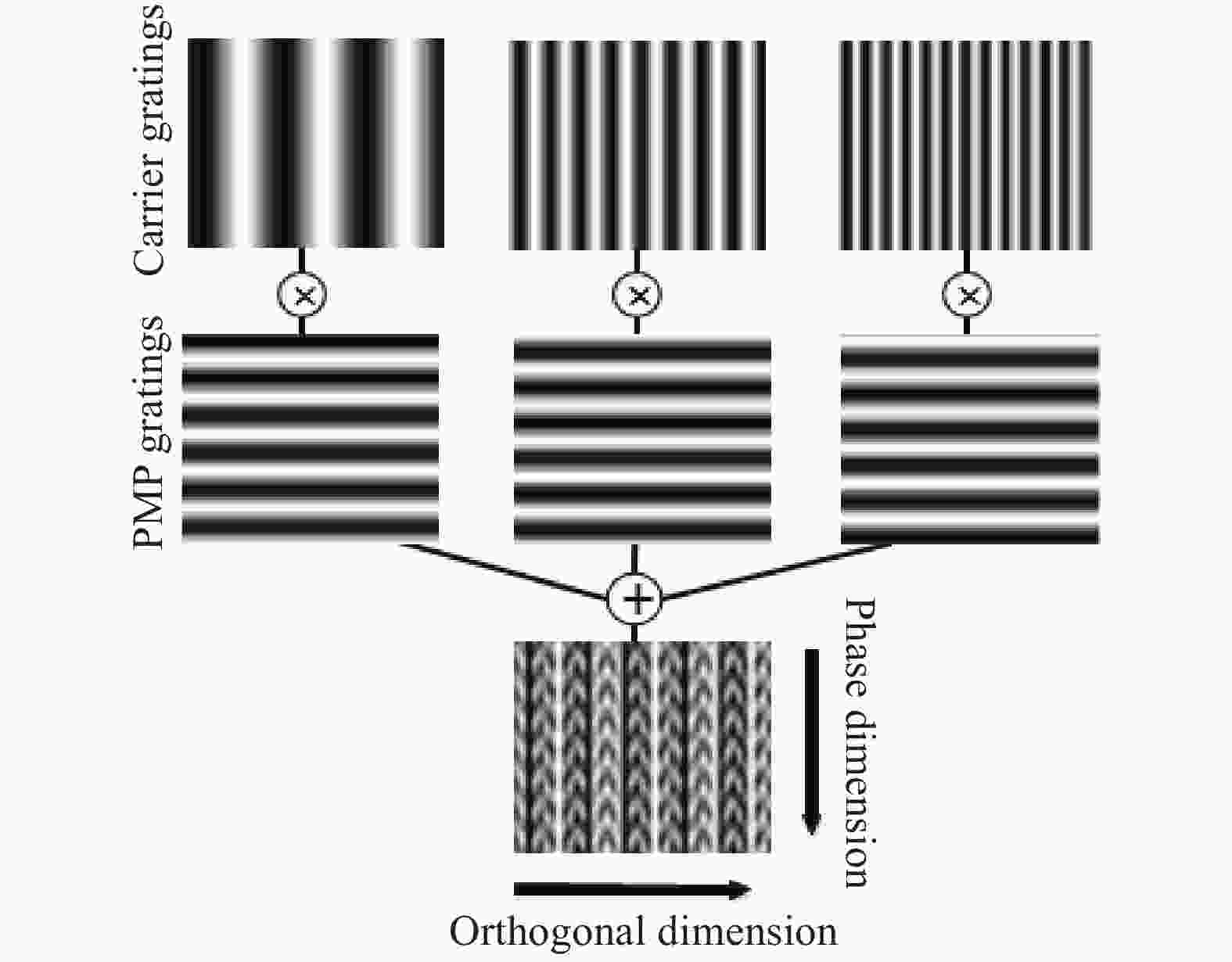
图 1 正交复合光栅复合过程
Figure 1. Procedure of orthogonal composite grating
通过投影一帧复合光栅图像到物体表面,CCD获取经物体调制后的变形光栅图像,经过滤波程序,得到N幅携带物体形貌特征的相移变形条纹图,经过相位计算、相位展开和高度映射,重建物体的三维面形。
编码的复合光栅表达式为:
$$I_p^{256}({x^p},{y^p}) \!=\! {\rm{INT}}8\left\{ {C \!+\! D\sum\limits_{n = 1}^N {I_n^p} ({x^p},{y^p})\cos (2{\text{π}} f_n^p{x^p})} \right\}$$ (1) 式中:
${\rm{INT}}\left\{ \bullet \right\}$ 表示8 bit无符号取整算子;$I_n^p({x^p},{y^p})$ 为N幅调制的正弦相移光栅:$$I_n^p({x^p},{y^p}) = A + B\cos (2{\text{π}} f_\varphi ^p{y^p} + 2{\text{π}} n/N)$$ (2) 式中: n=1,2,3.....,N为载频序数;A和B、
$f_\varphi ^p$ 分别为被调制的相移正弦光栅的背景光、对比度和空间频率;$\left( {{x^p},{y^p}} \right)$ 为投影坐标,${y^p}$ 方向为物体高度引起的相位变化方向,与之垂直的${x^p}$ 方向为正交方向;$f_n^p$ 是平行于正交方向的载波频率;C、D为两个常数,由以下公式计算:$$D = ({I_{{{{\rm{max}}}}}} - {I_{{{{\rm{min}}}}}})/\left( \begin{array}{l} ({\rm{max}}\left\{ {\sum\limits_{n = 1}^N {I_n^Pcos(2{\text{π}} f_n^P{x^p})} } \right\} \\ - {\rm{min}}\left\{ {\sum\limits_{n = 1}^N {I_n^Pcos(2{\text{π}} f_n^P{x^p})} } \right\} \\ \end{array} \right)$$ (3) $$C = {I_{{\rm{min}}}} - D{\rm{min}}\left( {\sum\limits_{n = 1}^N {I_n^Pcos(2{\text{π}} f_n^P{x^p})} } \right)$$ (4) $\left[ {{I_{{\rm{min}}}},{I_{{\rm{max}}}}} \right]$ 为与DLP投影强度一致的正交复合光栅的光强范围,通常落在[0,255]灰阶范围内。${\rm{max}}\left\{ \bullet \right\}$ 表示取最大值算子,${\rm{min}}\left\{ \bullet \right\}$ 表示取最小值算子。将光栅$I_p^{256}({x^p},{y^p})$ 投射到被测物体表面后,经过物体反射后CCD拍摄到的变形条纹图为:$$I_{}^{256}(x,y) = r({x^s},{y^s})\left\{ {{\rm{c}} + d\sum\limits_{n = 1}^N {I_n^s} ({x^s},{y^s})\cos (2{\text{π}} f_n^s{x^s})} \right\}$$ (5) 式中:
$r({x^s},{y^s})$ 为物体的反射率;$({x^s},{y^s})$ 代表CCD像素坐标;$I_n^s({x^s},{y^s})$ 为第n帧变形相移条纹图。$$I_n^s({x^s},{y^s}) = a + bcos\left[ {2{\text{π}} f_\varphi ^s{y^s} + \phi ({x^s},{y^s}) + 2{\text{π}} n/N} \right]$$ (6) 通过对变形条纹图快速傅里叶变换得到其频谱,在光栅相移方向设置对应的滤波器滤掉载频,再进行傅里叶逆变换得到。a,b为背景光和对比度,
$\phi ({x^s},{y^s})$ 为物体高度所引起的相位变化值。基于N帧相移变形条纹图计算反应物体高度的相位信息如公式(7)所示:$$\phi ({x^s},{y^s}) = \arctan \left[ {\frac{{\sum\limits_{n = 1}^N {I_n^s} ({x^s},{y^s})\sin (2{\text{π}} n/N)}}{{\sum\limits_{n = 1}^N {I_n^s} ({x^s},{y^s})\cos (2{\text{π}} n/N)}}} \right]$$ (7) 物体相位信息包裹在[-π,π)之间,通过相位展开算法获得连续的相位信息,综合考虑参考面与被测物面信息得到仅受物体高度调制的连续相位
$\psi (x,y)$ ,通过被测物体高度-相位映射关系[20]公式(8)重建物体高度信息。$$\frac{1}{{h(x,y)}} = \alpha (x,y) + \beta (x,y)\frac{1}{{\psi (x,y)}} + \gamma (x,y)\frac{1}{{\psi {{(x,y)}^2}}}$$ (8) 式中:
$\alpha (x,y)$ 、$\beta (x,y)$ 和$\gamma (x,y)$ 均为系统常数,可通过系统标定获得。 -
由于商用DLP的256灰度动态范围的标准限制[17],由OCG测量方法的原理可知,调制进复合光栅的多幅正弦相移光栅共享256个灰阶动态范围而致各幅调制光栅动态范围受到压缩,表达物体面形特征的相位信息受到压缩,引起相位展开环节的展项极点增多,增大解相误差,甚至导致相位断裂而发生物体重建不完整现象。为了解决这一问题,文中提出了一种基于灰度拓展复合光栅的单帧三维测量方法。流程图如图2所示。
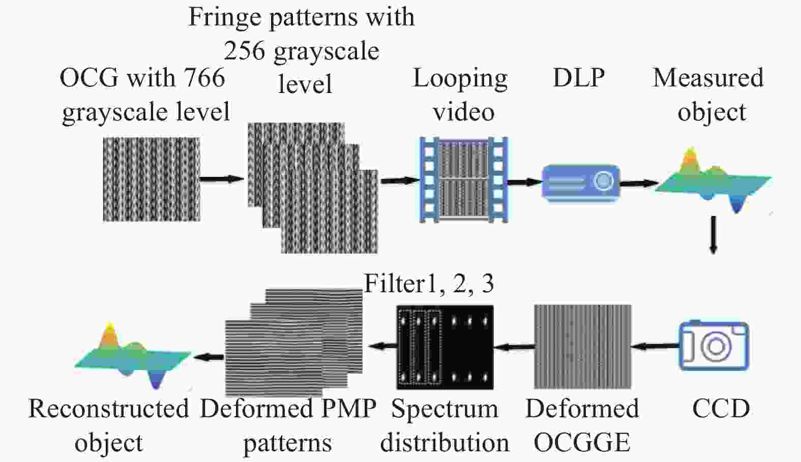
图 2 基于灰度拓展的正交复合光栅测量流程
Figure 2. Procedure of OCGGE
首先,设计一个期望具有766灰度动态范围的正交复合光栅图像为:
$$I_p^{766}({x^p},{y^p}) = INT16(C + D\sum\limits_{n = 1}^N {I_n^p} ({x^p},{y^p})\cos (2{\text{π}} f_n^p{x^p}))$$ (9) 有效相位信息为10 bit,N=3,投影常数
C、D的计算以获得最优的被测物的深度信息 $\left[ {{I_{{\rm{min}}}},{I_{{\rm{max}}}}} \right]$ 落在[0,765]之间。$$D = 765/\left( \begin{array}{l} (\max\left\{ {\sum\limits_{n = 1}^N {I_n^Pcos(2{\text{π}} f_n^P{x^p})} } \right\} - \\ \min\left\{ {\sum\limits_{n = 1}^N {I_n^Pcos(2{\text{π}} f_n^P{x^p})} } \right\} \end{array} \right)$$ (10) $$C = - D\min\left( {\sum\limits_{n = 1}^N {I_n^Pcos(2{\text{π}} f_n^P{x^p})} } \right)$$ (11) 虽然理论设计的OCGGE具有766灰阶动态范围,但是由于商用DLP的标准限制其只能投射256灰阶动态范围的光栅图像,如果直接将设计的具有766灰阶动态范围的复合光栅投射到被测物体表面,DLP将自动压缩其灰阶范围在[0,255]范围内,难以达到灰阶拓展的目的。如果直接投影256灰阶动态范围的复合光栅图像
$I_p^{256}({x^p},{y^p})$ ,设置CCD的曝光时间为DLP刷新周期的3 m倍,获得的灰度值为:$$ F\left( {x,y} \right) = 3m*I_p^{256}({x^p},{y^p})\;\;\;m = 1,2,3.... $$ (12) 采集到的最大灰阶个数为255×1+1=256个,即只能增大对应点整体亮度而不能达到增大灰阶动态范围的目的。由时分复用原理可知,如果将正交复合光栅图像均匀拆分为3幅图像并依次投影,调整CCD积分时间为三幅图像投影周期的m倍,采集得到图像灰度值为:
$$ {F^e}\left( {x,y} \right) = m*\sum\limits_{i = 1}^N {I_p^{256}(x_i^p,y_i^p)} \;\;\;m = 1,2,3\ldots $$ (13) 采集到的最大灰阶个数为255×3+1=766个,因此正交复合光栅
$I_p^{766}$ 拆分为3幅具有256动态范围的正交复合光栅图像需满足以下要求:$$\left\{ \begin{aligned} & I_p^{766} = I_1^{256}+I_2^{256}+ I_3^{256}\\ & \left| {I_i^{256} - I_j^{256}} \right| \le 1\;i = 1,2,3;\;j = 1,2,3 \end{aligned} \right.$$ (14) 如果直接依次投射所拆分的三幅复合条纹图,每幅图像投射需要较长时间,且各幅图像投射时间会因程序指令差异而导致不一致,采集图像一方面会因设置CCD曝光时间较长而过饱和失真,另一方面会因不同图像投射时间的差异性而使不同时刻采集的图像灰度存在差异,导致图像采集的不稳定。为此,提出了将三幅静态图像依次连续地加载进视频,用重复视频播放投影替换传统静态图像投影,这样一方面使CCD曝光时间显著缩短以确保采集的变形条纹图不致饱和失真,另一方面会因视频刷新帧率的稳定而确保图像采集的稳定。为了进一步量化分析,设视频中每帧图像的播放周期为
${t_0}$ ,完成三帧条纹投影的完整周期为$t = 3{t_0}$ ,如果调整CCD的曝光时间为t的整数m倍即${T_{{\rm{CCD}}}} = mt$ ,这样无需考虑DLP与CCD同步,只要选择10 bit及以上的CCD即可采集到动态范围为[0,755]的组合变形条纹图。此时采集到的组合变形条纹表达式可表示为:
$$I^{766}(x,y) = r({x^e},{y^e})({{c}} + d\sum\limits_{n = 1}^N {I_n^{\rm{e}}} ({x^e},{y^e})\cos (2{\text{π}} f_n^e{x^e}))$$ (15) 通过傅里叶变换后通过选择恰当的滤波器滤波得到三帧变形相移条纹图像:
$$I_n^e({x^e},{y^e}) = {{a}} + bcos[2{\text{π}} f_\varphi ^e{y^e} + \phi ({x^e},{y^e}) + 2{\text{π}} n/N]$$ (16) 物体相位信息
$\phi ({x^e},{y^e})$ 同理可通过公式(7)计算得到,经相位展开与相位-高度映射算法即可重建被测物体的三维面形。 -
为了充分验证所提方法的实用性与有效性,进行了多次实验测量。实验系统主要包括一台DLP(View Sonic PLED-W200,标准分辨率1 200×800,最大刷新频率为75 fps),一台高速CCD(BEV-B1610M相机,空间分辨率为1 628×1 236,文中使用信息输出格式为10 bit的二进制输出格式文件)、一台联想电脑(配置为Intel(R) core(TM) i5-4590 CPU @ 3.30 GHz and 1.86 GHz 8 GB 物理内存)。为了获取具有766灰阶动态范围的变形条纹图,首先设计766灰度动态范围的正交复合光栅,然后按照公式(14)拆分后的三幅图像制成帧率为60 fps的循环播放的视频,即
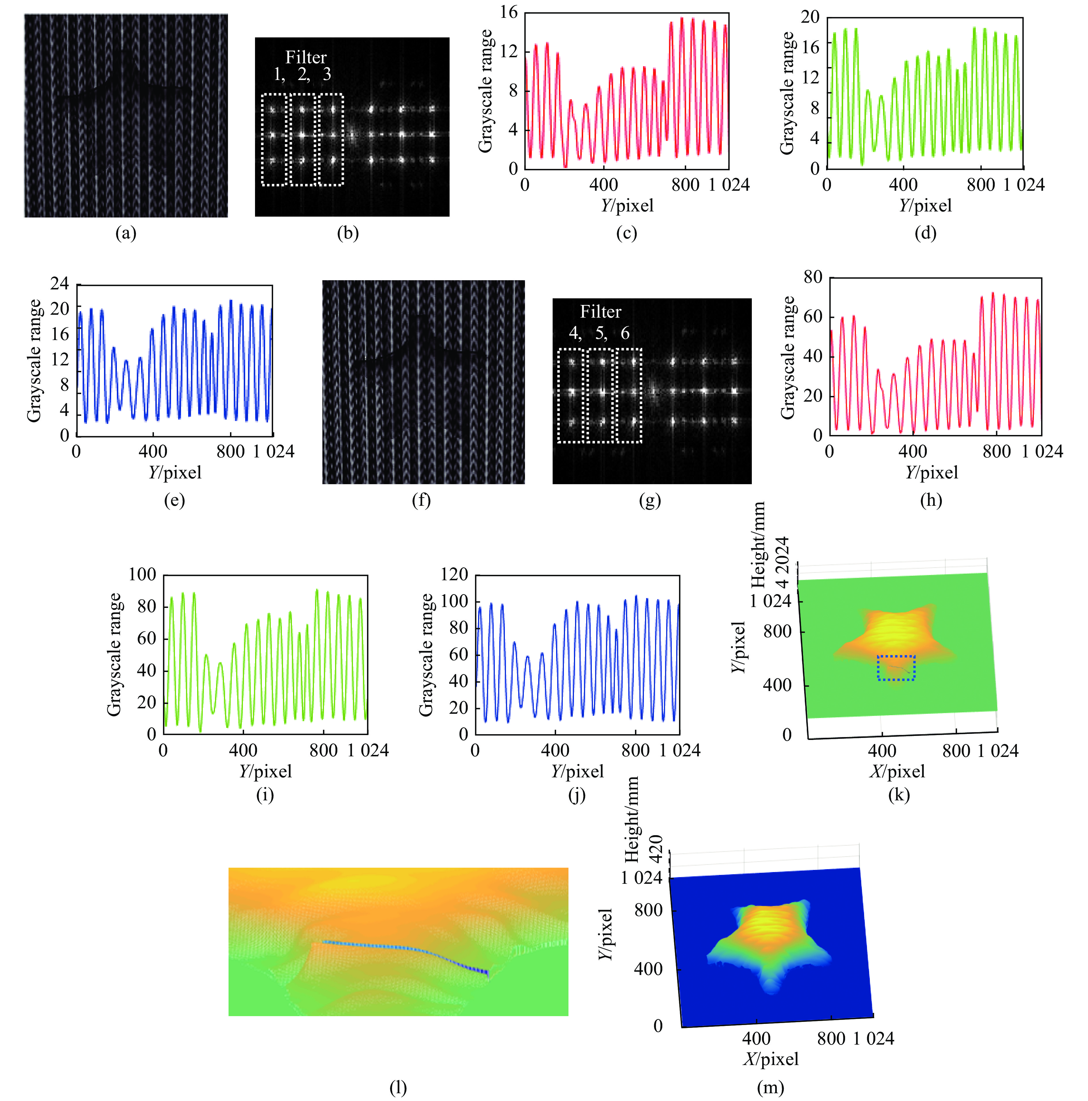
${t_0}$ =1/60 s,循环播放的视频经DLP投射到参考面与被测物体表面,按所提方法设置CCD曝光时间,即TCCD=3t0,合理调节增益,即可采集所需的高动态范围条纹图。分别使用OCG与文中所提OCGGE方法对同一星形物体进行测量并进行对比分析。两种方法的测量过程与结果如图3所示。图3(a)、3(f)分别表示OCG和OCGGE方法的变形光栅图,图3(b)、3(g)表示OCG和OCGGE方法的变形光栅图经二维快速傅里叶变换后的频谱分布图。图3(c)、3(d)、3(e)代表OCG法经过滤波器滤波后得到的三幅变形相移条纹图第512列的剖面图,图3(c)灰阶为15.29,图3(d)的灰阶为18.61,图3(e)的灰阶为22.45,三帧图灰阶均值为18.78;图3(h)、3(i)、3(j)代表OCGGE法经过三个滤波器滤波后得到的三幅变形相移条纹图第512列的剖面图,图3(h)的灰阶为72.30,图3(i)的灰阶为90.66,图3(j)的灰阶为104.69,图3(h)、3(i)、3(j)灰阶均值为89.22,对比两种方法的灰阶,OCGGE法的灰阶为OCG方法的的4.75倍,明显大于OCG方法的灰阶,其能反应更多和更强的被测物体特征信息。OCG方法的重建结果如图3(k)所示,可以看出,在星形的一角出现断裂现象,其局部放大图如图3(l)所示,反应了采用OCG方法进行测量由于受调制的正弦相移光栅灰阶信息受到压缩,有效相位信息减少而使相位极点增多,在相位展开环节出现了相位断裂现象而引起了物体面形重建不完整现象。OCGGE方法的重建结果如图3(m)所示,能够完整地重建星形物体,反应了所提方法能够保留物体更多更强的特征信息,提高解相精度而保证物体的三维面形能够完整重建。
图 3 OCG和OCGGE方法的实验对比。(a),(f)OCG与OCGGE的变形条纹图;(b),(g)OCG和OCGGE方法的频谱分布;(c),(d),(e)OCG方法从滤波器1,2,3中提取的变形相移条纹图在第512列的截面图;(h),(i),(j)OCGGE方法从滤波器4,5,6中提取的变形相移条纹图在第512列的截面图;(k)OCG的重建结果;(l)图3(k)中虚线框的局部放大图;(m)OCGGE方法的重建结果
Figure 3. Experimental contrast between OCG and OCGGE. (a), (f) Deformed pattern of OCG and OCGGE; (b), (g) spectrum distribution of OCG and OCGGE; (c), (d), (e) OCG cutaway views at column 512 of the deformed phase shifting fringe patterns extracting from filter1, filter2, filter3; (h), (i), (j) OCGGE cutaway views at column 512 of the deformed phase shifting fringe patterns extracting from filter4, filter5, filter6; (k) reconstructed result of OCG; (l) zoom in on the dashed box from Fig.3(k); (m) reconstructed result of OCGGE
为了进一步验证所提方法的有效性与测量精度,分别使用测量精度高的八步PMP方法、传统的OCG方法和文中所提OCGGE方法对一具有复杂面形的人脸进行测量并比较分析,实验结果如图4所示。

图 4 OCG, OCGGE和PMP方法实验结果对比。(a)被测物体;(b)OCGGE方法所获取的变形条纹图;(c)OCGGE方法重建的三维面形;(d)三种方法在第476列的剖面图;(e)图4(d)中短划线框的局部放大图;(f)图4(d)中方点线框的局部放大图
Figure 4. Comparison results between OCG, OCGGE and PMP. (a) Measured object; (b) deformed pattern of OCGGE; (c) reconstructed result with OCGGE; (d) cutaway view at column 476 with OCG, OCGGE and PMP; (e) magnified view of the dashed box from Fig. 4(d); (f) magnified view of the point line box from Fig. 4(d)
图4(a)表示具有复杂面形的被测人脸模型,图4(b)表示采集到的使用OCGGE方法的变形条纹图,4(c)表示使用OCGGE方法重建的物体三维形貌;图4(d)表示使用OCG、OCGGE和八步PMP三种方法重建的物体在第476列的截面图,可以看出OCGGE方法的面形重建结果优于传统的OCG方法而更接近八步PMP的重建结果。进一步对物体面形凸起处如图3中的点划线框和方点线框凸起处的局部放大图如图4(e)和图4(f)分析,可以看出对于物体突变部位OCGGE的重建精度明显优于OCG方法。表明采用OCGGE方法能够保留被测物体更多更强的特征信息使对于复杂面形突变部位有更高的重建精度。
-
由于商用DLP灰阶动态范围标准为256灰阶,由多帧正弦相移光栅调制而成的复合光栅共享256灰阶动态范围,各帧正弦光栅的条纹动态范围受到压缩,使重构物体面形的细节信息丢失,导致解相极点增多,甚至导致相位展开出现断裂或不能完整重建物体三维面形的现象。文中提出了灰度拓展的单帧复合光栅三维测量方法,将复合光栅的灰度动态范围设计为766灰阶,基于时分复用原理,用投影视频复合光栅替换传统投影静态复合光栅,实现了采集高动态范围的复合变形条纹图,不受DLP[0,255]灰阶投影标准限制,所提方法能够拓展调制的相移光栅的灰阶,丰富被测物面细节信息,减少相位误差点,避免相位展开时的相位断裂而导致相位信息重建不完整现象。
Single-shot 3D measurement using grayscale expanded composited grating
-
摘要:
提出了一种基于灰度拓展的单帧正交复合光栅三维测量方法。由于受商用DLP最大灰阶动态范围256的标准限制,单帧复合光栅中的多张调制光栅共享256灰阶动态范围导致其对比度变小,其表征的三维物体的相位信息被压缩,解相过程出现相位断裂现象,测量误差增大。采用时分复用原理,将一具有766灰阶的正交复合光栅拆分为三幅不同的具有256灰阶的条纹图。依次序加载进循环播放的视频中投射至待测物体表面,当用曝光时间为3倍视频刷新周期的整数倍10 bit CCD采集时,就可采集到具有766灰阶动态范围的变形复合光栅像。通过滤波和灰度校准等计算后,物体的三维面形能够完整而精确的重建。经仿真和实验验证,所提方法打破了DLP256灰度投影的限制,有效提高了相移变形条纹的动态范围,增大了被测物体细节信息,避免了相位展开环节相位断裂而引起物体面形重构不完整的现象。
Abstract:A single-shot 3D shape measurement using orthogonal composited grating based on grayscale expanding (OCGGE) was proposed. In the traditional orthogonal composited grating (OCG) profilometry, the modulated gratings in the orthogonal composited grating must share the same grayscale level since the maximal grayscale dynamic range of commercial Digital Light Processing (DLP) is limited in 256, that results in some phenomenon increasing the measuring error, including the weakened contrast of the modulated grating, the compressed phase information and the broken phase during the process of phase unwrapping. Based on the principle of time division multiplexing, one orthogonal composited grating was designed with 766 gray level and was spited into three different fringe patterns with 256 grayscales, then loaded these patterns in sequence to edit a video. When this video was played and projected onto the measured object continuously, by setting the exposure time as an integer times of the 3 times of the frame refresh cycle of the video for a 10bit CCD, a deformed pattern with 766 grayscales could be obtained. After the filtering and grayscale calibration, the object could be reconstructed accurately and completely. Both simulation and experiment results prove that the proposed method can break the limit of 256 grayscale projection and increase the dynamic range of the phase-shifting deformed patterns efficiently. And it can also enrich the detailed information of the measured object and avoid the incomplete surface reconstruction caused by phase break.
-
图 3 OCG和OCGGE方法的实验对比。(a),(f)OCG与OCGGE的变形条纹图;(b),(g)OCG和OCGGE方法的频谱分布;(c),(d),(e)OCG方法从滤波器1,2,3中提取的变形相移条纹图在第512列的截面图;(h),(i),(j)OCGGE方法从滤波器4,5,6中提取的变形相移条纹图在第512列的截面图;(k)OCG的重建结果;(l)图3(k)中虚线框的局部放大图;(m)OCGGE方法的重建结果
Figure 3. Experimental contrast between OCG and OCGGE. (a), (f) Deformed pattern of OCG and OCGGE; (b), (g) spectrum distribution of OCG and OCGGE; (c), (d), (e) OCG cutaway views at column 512 of the deformed phase shifting fringe patterns extracting from filter1, filter2, filter3; (h), (i), (j) OCGGE cutaway views at column 512 of the deformed phase shifting fringe patterns extracting from filter4, filter5, filter6; (k) reconstructed result of OCG; (l) zoom in on the dashed box from Fig.3(k); (m) reconstructed result of OCGGE
图 4 OCG, OCGGE和PMP方法实验结果对比。(a)被测物体;(b)OCGGE方法所获取的变形条纹图;(c)OCGGE方法重建的三维面形;(d)三种方法在第476列的剖面图;(e)图4(d)中短划线框的局部放大图;(f)图4(d)中方点线框的局部放大图
Figure 4. Comparison results between OCG, OCGGE and PMP. (a) Measured object; (b) deformed pattern of OCGGE; (c) reconstructed result with OCGGE; (d) cutaway view at column 476 with OCG, OCGGE and PMP; (e) magnified view of the dashed box from Fig. 4(d); (f) magnified view of the point line box from Fig. 4(d)
-
[1] Gao Peng, Wen Kai, Sun Xueying, et al. Review of resolution enhancement technologies in quantitative phase microscopy [J]. Infrared and Laser Engineering, 2019, 48(6): 0603007. (in Chinese) doi: 10.3788/IRLA201948.0603007 [2] Zhang Wenhui, Cao Liangcai, Jin Guofan. Review on high resolution and large field of view digital holography [J]. Infrared and Laser Engineering, 2019, 48(6): 0603008. (in Chinese) doi: 10.3788/IRLA201948.0603008 [3] Zhang Lei, Liu Dong, Shi Tu, et al. Optical free-form surfaces testing techonlogies [J]. Chinese Optics, 2017, 10(3): 283−299. (in Chinese) doi: 10.3788/co.20171003.0283 [4] Zuo C, Feng S J, Huang L, et al. Phase shifting algorithms for fringe projection profilometry: A review [J]. Optics and Lasers in Engineering, 2018, 109: 23−59. doi: 10.1016/j.optlaseng.2018.04.019 [5] Shang Wanqi, Zhang Wenxi, Wu Zhou, et al. Three-dimensional measurement system based on full-field heterodyne interferometry [J]. Optics and Precision Engineering, 2017, 46(3): 251−259. (in Chinese) [6] Chen Chao, Yu Yanqin, Huang Shujun, et al. 3D small-field imaging system [J]. Infrared and Laser Engineering, 2016, 45(8): 0824002. (in Chinese) doi: 10.3788/IRLA201645.0824002 [7] Wang Z Z, Yang Y M. Single-shot three- dimensional reconstruction based on structured light line pattern [J]. Optics and Lasers in Engineering, 2018, 106: 10−16. doi: 10.1016/j.optlaseng.2018.02.002 [8] Wu Yingchun, Cao Yiping, Xiao Yanshan. On-line three-dimensional inspection using randomly phase-shifting fringe based on least-square iteration [J]. Optics and Precision Engineering, 2014, 22(5): 1347−1353. (in Chinese) doi: 10.3788/OPE.20142205.1347 [9] Zhang Z H. Review of single-shot 3D shape measurement by phase calculation-fringe projection techniques [J]. Optics and Lasers in Engineering, 2012, 50(8): 1097−1106. doi: 10.1016/j.optlaseng.2012.01.007 [10] Wang Jianhua, Yang Yanxi. Double N-step phase-shifting profilometry using color-encoded grating projection [J]. Chinese Optics, 2019, 12(3): 616−626. (in Chinese) doi: 10.3788/co.20191203.0616 [11] Takeda M. Fourier transform profilometry for the automatic measurement of 3-D object shapes [J]. Appl Opt, 1983: 22. [12] Guan C, Hassebrook L G, Lau D L. Composite structured light pattern for three-dimensional video [J]. Optics Express, 2003, 11(5): 406−417. doi: 10.1364/OE.11.000406 [13] He Yuhang, Cao Yiping, Zhai Aiping. A 3-D measurement method with orthogonal composite light based on fringe contrast and background calibration [J]. Acta Optica Sinica, 2010, 30(11): 3191−3196. (in Chinese) doi: 10.3788/AOS20103011.3191 [14] Zhai Aiping, Cao Yiping, He Yuhang. 3D measurement with orthogonal composite structure light based on two-plus-one phase-shifting algorithm [J]. Chinese Journal of Lasers, 2012, 39(2): 147−152. (in Chinese) [15] He Y H, Cao Y P. Shifted-phase calibration for a 3-D shape measurement system based on orthogonal composite grating projection [J]. Optik, 2011, 122(19): 1730−1734. doi: 10.1016/j.ijleo.2010.10.033 [16] He D W, Cao Y P, He D G, et al. Optimized design of composite grating in real-time three-dimensional shape measurement [J]. Optik, 2015, 126(21): 2781−2787. doi: 10.1016/j.ijleo.2015.07.003 [17] Zhang Lizhen, Cao Yiping, Fu Guangkai, et al. Application of grayscale expansion for accuracy improvement in phase-measuring profilometry [J]. Displays, 2019, 59: 28−34. doi: 10.1016/j.displa.2019.06.001 [18] Cao Yiping, Su XianYu, Chen Wenjing, et al. Effect on the phase measuring profilometer to the spatio-temporal characteristic of DMD [J]. Optical Technique, 2004, 30(2): 157−160. (in Chinese) [19] Wang Z Z. Robust measurement of the diffuse surface by phase shift profilometry [J]. Journal of Optics, 2014, 16(10). [20] Ma Q N, Cao Y P, Chen C, et al. Intrinsic feature revelation of phase-to-height mapping in phase measuring profilometry [J]. Optics & Laser Technology, 2018, 108: 46−52. -

 点击查看大图
计量
- 文章访问数: 464
- HTML全文浏览量: 225
- 被引次数: 0


