


-
关联成像作为一种新型的成像技术近年来受到了国内外广大学者的持续关注。最早的关联成像由Pittman等[1]利用自发参量下转换过程产生具有量子纠缠特性的信号光和闲置光,通过符合计数获取待测物体的空间分布信息,后来的实验和理论表明经典热光源也能实现关联成像[2]。通常关联成像系统中光源发出的光被分成两路:参考光和信号光;其中参考光不经过物体,其强度分布被一具有空间分辨能力的探测器探测,信号光照射到成像物体,与物体相互作用后被一点探测器(如光电倍增管)收集。通过对两路光场的强度值进行相关计算,可复原成像物体的空间信息。在实际应用时,关联成像系统通常省略掉参考光路,采用一可编程的空间光调制器产生空间分布预知的调制散斑来照明目标物体,物体反射或者透射的光强经单像素探测器收集,单像素探测器收集的光强与预知的调制散斑经相关运算来复原成像物体的图像,此时该系统也称之为计算关联成像[3]或者单像素成像[4],这种简化推动了关联成像技术向实用化方向发展,目前关联成像在三维成像[5]、气体成像[6]、目标跟踪[7]等领域展现了独特的应用前景。
光谱成像是光谱技术与成像技术的有机结合[8]。其中,多光谱成像是光谱成像的一种,是指光谱分辨率在100 nm左右,包含3~10个光谱通道的光谱成像。相对于单一波段的成像系统,多光谱成像获得的目标光谱图像更丰富、全面。当前,无论是采用面阵探测器的传统多光谱成像[9]或者多光谱关联成像技术[10],通常采用光学分光的方式使用多个不同中心波长的探测器来获得相应光谱的图像,对多个光谱通道的图像进行融合来实现多光谱图像。此类多光谱成像技术系统复杂、数据量大。我们在前期的研究中提出通过复用的方法[11-12],采用随机散斑融合编码矩阵来构造投影散斑,基于关联成像技术实现多光谱成像,然而由于随机散斑之间的冗余性,复原的混叠光谱图像与多光谱图像质量不够理想,在图像复原阶段使用了四次压缩感知算法,使得整个复原计算比较耗时。
针对现有技术的不足,文中在前期的研究基础之上提出基于正交调制模式的光谱编码计算关联成像技术。通过构造满足一定约束条件的正交编码矩阵与Hadamard基图案融合后生成调制散斑对光源进行调制,调制后的光源与目标物体相互作用后,单像素探测器收集目标物体后向散射信号。通过演化压缩技术复原目标物体的混叠光谱图像,然后利用编码矩阵正交性质分别对混叠光谱图像进行解调,对分离出的欠采样光谱分量图像应用组稀疏压缩感知算法重构全采样光谱通道图像,最后对光谱通道图像进行融合构建出成像物体的多光谱图像。文中分别从理论分析、数值模拟与实验三方面对所提方法进行了阐述与评估验证。所提方法简化了多光谱成像系统结构,降低了数据量。相应的光谱编码策略可以应用在偏振成像以及信息加密等领域。像以及信息加密等领域。
-
光谱编码计算关联成像是通过对光源进行编码来实现的。通过三个光谱通道进行介绍,对多于三个光谱通道的处理方法与三个通道处理方法一样。首先构造三个随机分布的N×N二维编码矩阵,分别对应R、G和B三种颜色通道,将这三个编码矩阵分别记为ER、EG和EB,并且这三个编码矩阵应满足如下约束条件:
$${{E}_{\rm{R}}}+ {{E}_{\rm{G}}}{\rm{ + }}{{E}_{\rm{B}}}\;{\rm{ = }}\left[ {\begin{array}{*{20}{c|ccccccc}} 1& & 1&.&.&.&1&1 \\ \hdashline[2pt/2pt]\\ 1& & 1&.&.&.&1&1 \\ .& & .&.&.&.&.&. \\ .& & .&.&.&.&.&. \\ \hdashline[2pt/2pt]\\ .& & .&.&.&.&.&. \\ 1& & 1&.&.&.&1&1 \\ 1& & 1&.&.&.&1&1 \end{array}} \right]$$ (1) $${{{E}}_{{m}}} \cdot {{{E}}_{{n}}}{\rm{ = }}\;\left\{ \begin{array}{l} {{0 \;\;\; \;\; n}} \ne {{m}} \\ {{{E}}_{{n}}}\;\;\;{{n}}\;{\rm{ = }}\;{{m}} \\ \end{array} \right.\;\;{{n,}}\;\;{{m}}\;{\rm{ = }}\;{\rm{R,}}\;{\rm{G,}}\;{\rm{B}}$$ (2) 公式(2)中·表示点乘运算。从公式(1)和(2)可以看出,编码矩阵是相互正交的二值化矩阵,且编码矩阵的和为一N×N的全1矩阵。计算机产生确定性正交Hadamard基矩阵Si,分别与编码矩阵点乘来构造出如下模式的投影散斑Ii:
$${I_{i}}={E_{\rm{R}}} \cdot \;{S}_{{i}}{\rm{ + }}{{{E}}_{\rm{G}}} \cdot \;{{\rm{S}}_{i}}{\rm{ + }}{{{E}}_{\rm{B}}} \cdot \;{{{S}}_{i}}$$ (3) 式中:ER·Si、EG ·Si和EB ·Si分别对应了各自光谱通道的投影散斑,将它们同时加载到调制系统中对宽带光源进行调制,调制后的宽带光源与成像物体相互作用后,产生的后向散射信号被单像素探测接收,表示为Ui:
$$\begin{split} {{{U}}_{{i}}}{{ = }}&\displaystyle\sum_{{{i = 1}}}^{{{N}} \times {{N}}} {{{\{ (r}} \cdot {{{E}}_{\rm{R}}} \cdot {{{S}}_{{i}}} \cdot {{{T}}_{\rm{R}}}{{) + (g}} \cdot {{{E}}_{\rm{G}}} \cdot {{{S}}_{{i}}} \cdot {{{T}}_{\rm{G}}})} + \\ &{{ (b}} \cdot {{{E}}_{\rm{B}}} \cdot {{{S}}_{{i}}} \cdot {{{T}}_{\rm{B}}}{{)\} }} \\ \end{split} $$ (4) 式中:常数R、G和B分别为光电探测器对红、绿、蓝三种光谱的响应系数,可以通过标定来获得;TR、TG和TB分别对应待测的目标物体三种光谱信息。可以将公式(4)简化如下:
$${{{U}}_{{i}}}{{ = }}\sum\limits_{{{i = 1}}}^{{{N}} \times {{N}}} {{{{S}}_{{i}}} \cdot {{T}}} \;\;\;$$ (5) 式中:T表示成像物体的混叠光谱图像,其可用下式进行表示:
$${{T = r}} \cdot {{{E}}_{\rm{R}}} \cdot {{{T}}_{\rm{R}}}{{ + g}} \cdot {{{E}}_{\rm{G}}} \cdot {{{T}}_{\rm{G}}}{{ + b}} \cdot {{{E}}_{\rm{B}}} \cdot {{{T}}_{\rm{B}}}$$ (6) 公式(5)中的Si为确定性的正交Hadamard基模式图案,因此公式(5)可由迭代算法复原,此时目标物体N×N维的混叠光谱图像T可通过下式计算:
$${{T = }}\frac{{{1}}}{{{{N}} \times {{N}}}}\sum\limits_{{{k = 1}}}^{{{N}} \times {{N}}} {{{{U}}_{{k}}}} \cdot {{{S}}_{{k}}}{{, k = 1, 2, }}\cdots{{ N}} \times {{N}}$$ (7) 当目标物体的混叠光谱图像T获得之后,根据编码矩阵的正交性质,将其分别与混叠光谱图像T做点乘运算可以分离出目标物体三个通道的光谱图像YR、YG和YB,即:
$$\begin{array}{l} {{{Y}}_{\rm{R}}}{\rm{ = }}{E_{\rm{R}}} \cdot {{T = }}{E_{\rm{R}}} \cdot {{r}} \cdot {{{T}}_{\rm{R}}} \\ {{{Y}}_{\rm{G}}}{\rm{ = }}{E_{\rm{G}}} \cdot {{T = }}{E_{\rm{G}}} \cdot {{g}} \cdot {{{T}}_{\rm{G}}}\;\; \\ {{{Y}}_{\rm{B}}}{\rm{ = }}{E_{\rm{B}}} \cdot {{T = }}{E_{\rm{B}}} \cdot {{b}} \cdot {{{T}}_{\rm{B}}} \\ \end{array} $$ (8) 此时,得到的光谱分量YR、YG和YB可以认为是TR、TG和TB (待复原的完整的光谱分量图像)分别被ER、EG和EB调制后的图像,这里YR、YG和YB为欠采样的光谱分量图像,而TR、TG和TB为全采样的光谱分量图像。通过基于组稀疏压缩感知图像复原算法[13]对公式(8)进行求解重构光谱分量图像TR、TG和TB,即:
$${{\overset\frown{\alpha }} _{_{{G_{\rm{R}}}}}} = \;\arg \;\mathop {\min }\limits_{{\alpha _{{G_{\rm{R}}}}}} \;\dfrac{1}{2}||\;{{{E}}_{\rm{R}}}r{D_{{G_{\rm{R}}}}} \circ {\alpha _{{G_{\rm{R}}}}}{\rm{ - }}{{{Y}}_{\rm{R}}}||_2^2 + \lambda ||{\alpha _{{G_{\rm{R}}}}}|{|_0}$$ (9) $${{\overset\frown{\alpha }} _{_{{G_{\rm{G}}}}}} = \;\arg \;\mathop {\min }\limits_{{\alpha _{{G_{\rm{G}}}}}} \;\dfrac{1}{2}||\;{{{E}}_{\rm{G}}}g{D_{{G_{\rm{G}}}}} \circ {\alpha _{{G_{\rm{G}}}}}{\rm{ - }}{{{Y}}_{\rm{G}}}||_2^2 + \lambda ||{\alpha _{{G_{\rm{G}}}}}|{|_0}$$ (10) $${{\overset\frown{\alpha }} _{_{{G_{\rm{B}}}}}} = \;\arg \;\mathop {\min }\limits_{{\alpha _{{G_{\rm{B}}}}}} \;\frac{1}{2}||\;{{\rm{E}}_{\rm{B}}}b{D_{{G_{\rm{B}}}}} \circ {\alpha _{{G_{\rm{B}}}}}{\rm{ - }}{{{Y}}_{\rm{B}}}||_2^2 + \lambda ||{\alpha _{{G_{\rm{B}}}}}|{|_0}$$ (11) 式中:
$\lambda $ 为规则化参数,其根据欠采样的光谱分量图像质量进行调整;${D_{{G_{\rm{R}}}}}$ 、${D_{{G_{\rm{G}}}}}$ 和${D_{{G_{\rm{ B}}}}}$ 分别为适应学习得到的稀疏基;${{\overset\frown{\alpha }} _{_{{G_ {\rm{R}}}}}}$ 、${{\overset\frown{\alpha }} _{_{{G_{\rm{G}}}}}}$ 和${{\overset\frown{\alpha }} _{_{{G_{\rm{B}}}}}}$ 为相应的稀疏系数。因此,光谱通道图像分别通过${{{T}}_{\rm{R}}}{\rm{ = }}{D_{{G_ {\rm{R}}}}} \circ {{\overset\frown{\alpha }} _{_{{G_{\rm{R}}}}}}$ 、${{{T}}_{\rm{G}}}{\rm{ = }}{D_{{G_{\rm{G}}}}} \circ {{\overset\frown{\alpha }} _{_{{G_{\rm{G}}}}}}$ 和${{{T}}_{\rm{B}}}{\rm{ = }} $ $ {D_{{G_{\rm{B}}}}} \circ {{\overset\frown{\alpha }} _{_{{G_{\rm{B}}}}}}$ 来重构。最终成像物体的多光谱图像通过融合全采样的光谱通道图像TR、TG和TB来获得。光谱编码计算关联成像技术的实现流程如图1所示。
图 1 光谱编码计算关联技术的实现流程
Figure 1. Implementation process of spectal encoded computational ghost imaging technology
总结上述过程,光谱编码计算关联成像技术的实现方法主要分为三步:第一步:投影散斑产生过程。计算机分别产生三个光谱编码矩阵和Hadamard基图案,构造出照明投影散斑CIP,其中图1中的HP表示Hadamard散斑(Hadamard Pattern, HP);CIP表示彩色照明散斑(Color Illumination Pattern, CIP);第二步:计算关联成像过程。通过构建的彩色投影散斑CIP对成像物体进行照明,物体与投影光源相互作用后,产生的后向散射信号被单像素探测器收集并记录为U,使用迭代算法复原成像物体的混叠光谱图像T;第三步:光谱图像复原过程。鉴于光谱编码矩阵ER、EG和EB相互正交的性质,混叠光谱图像T分别与其进行点乘运算,分离出三个通道的欠采样光谱分量图像YR、YG和YB,对其分别应用组稀疏压缩感知算法实现对分离的光谱图像进行重构,最后将复原的光谱分量TR、TG和TB融合出成像物体的多光谱图像,图1中的SI表示为光谱图像(Spectral Image)。
-
通过数值仿真来评估光谱编码计算关联成像的性能。成像分辨率设为256×256。构造的编码矩阵如图2所示,其中图2右下角的图像为256×256分辨率的Hadamard图案,投影时将Hadamard基图案的第一列与第一行相乘运算产生256×256的矩阵后与编码矩阵分别点乘运算来合成投影散斑,进行投影;第二个投影散斑为Hadamard图案中的第一列与第二行相乘运算产生256×256的矩阵后与编码矩阵分别点乘运算来合成投影散斑,依次进行投影。

图 2 光谱编码矩阵与Hadamard矩阵
Figure 2. Spectral encoded matrices and Hadamard matrix
仿真物体为256×256分辨率的二值化彩色物体,分别由红色字母R、绿色字母G和蓝色字母B构成。图3(a)展示了数值仿真中依次记录的65536个后向散射信号。应用演化压缩技术[14-15]来复原成像物体的混叠光谱图像,演化压缩技术是将探测信号按其绝对值大小进行排序,选取排列靠前的部分探测信号与其对应的Hadamard散斑进行目标图像的复原。图3(b)为排列后的信号。

图 3 (a)按投影顺序记录的物体散射信号;(b)按信号绝对值从大到小排序的结果
Figure 3. (a) Corrected scattered singal under the projection order; (b) Result in descending order according to the absolute value
分别选取图3(b)中前4096、8192、16384、32768、49152和65536个信号进行复原计算,相应的采样率(定义为Q=V/L,其中V为参与计算的投影散斑数量或者采样次数,L为全采样次数,这里L=65536)分别为6.25%、12.5%、25%、50%、75%和100%,相应的复原结果如图4(a)~(f)所示。以图4(a)为例,第一列图像为图3(b)中前4096个信号与对应的Hadamard图案进行迭代计算复原出的物体混叠光谱图像;第二列的三幅图像分别为物体混叠光谱图像分别与编码矩阵点乘运算分离出的欠采样光谱分量图像;第三列的三幅图像分别为组稀疏压缩感知复原得到的全采样光谱分量图像;第四列图像为融合三个通道的光谱分量后的物体多光谱图像。文中的光谱图像复原时间主要包括两部分,即混叠光谱图像复原时间与全采样光谱图像复原时间,在主频为1.8 GHz、i7-8550U处理器以及内存为8G的计算机上,使用64位Window10操作系统和Matlab R2018a软件,对65536次采样时复原256×256分辨率的混叠光谱图像耗时约为12.98 s,应用压缩感知复原三个通道全采样光谱分量图像的耗时约为6 min。从仿真结果中可以看出,即使在6.25%的采样率下,物体的混叠光谱图像也可以复原出来,物体的多光谱图像也能够分辨出物体各部分对应的颜色信息。随着采样率的增加,复原出的物体混叠光谱图像与多光谱图像质量逐渐增加。从采样率分别为50%、75%和100%时复原的物体混叠光谱图像与多光谱图像上已经很难明显看出差异性。

图 4 (a)~(f) 6.25%、12.5%、25%、50%、75%和100%采样率下的数值仿真结果
Figure 4. (a)-(f) Simulation results under sample ratio of 6.25%, 12.5%, 25%, 50%, 75% and 100%
为定量分析光谱编码计算关联成像的复原光谱图像质量,笔者采用均方差(Mean Squared Error,MSE,值越小,复原图像质量越好)和峰值信噪比(Peak Signal to Noise,PSNR,值越大,复原图质量越好)对复原图像进行评价,其定义分别如下:
$${\rm{MSE}} = [{{f}}({{x}},{{y}}) - {{{f}}_0}({{x}},{{y}})]^2/{{NM}}$$ (12) $${\rm{PSNR}} = 10 \times {\rm{log}}{_{10}}(255^2/{{{\rm{MSE}}}})$$ (13) 式中:f(x,y)和f0(x,y)分别为复原的图像与原始图像;N与M分别为图像的空间分辨率。这里分别对复原的三个通道的光谱通道分量TR、TG和TB与原始图像中对应的光谱通道图像进行计算,所有图像均归一化后进行计算。三个通道的均方差与峰值信噪比分别如表1和表2所示,随着采样率的增加,均方误差逐渐降低,峰值信噪比逐渐增加;当采样率大于50%时,峰值信噪比增加量变化很小。从仿真结果上可以看出光谱编码计算关联成像方法可以很好地实现多光谱成像。
表 1 不同采样率下复原光谱分量与原图之间的均方差
Table 1. MSE of the reconstructed spectral channel images and the corresponding original images under different sample ratio (SR)
SR 6.25% 12.5% 25% 50% 75% 100% TR 9.37% 7.00% 4.76% 1.62% 0.63% 0.48% TG 6.57% 5.22% 3.81% 1.36% 0.62% 0.48% TB 6.97% 5.37% 4.17% 1.41% 0.64% 0.53% 表 2 不同采样率下复原图像与原图之间的峰值信噪比
Table 2. PSNR of the reconstructed spectral channel images and the corresponding original images under different sample ratio (SR)
SR 6.25% 12.5% 25% 50% 75% 100% TR 58.42 59.68 61.35 66.02 70.17 71.28 TG 59.95 60.95 62.32 66.80 70.24 71.30 TB 59.70 60.83 61.93 66.64 70.06 70.90 -
从仿真的结果可以看出,由Hadamard基图案融合正交光谱编码矩阵构成的投影散斑可以高效地实现多光谱成像。此节开展相应的实验研究,搭建的系统结构如图5所示。成像系统可为投影部分、成像物体和光学接收与探测部分。限制于当前的实验室条件,在常用的投影器件(如数字微镜器件)的微镜表面涂覆相应的光谱材料来实现对宽带光源的调制还有一定的困难,这里采用基于数字光投影技术(Digital Light Processing,DLP)的投影仪(东芝TDP-98)来实现光源的调制和投影。计算机产生编码矩阵和Hadamard基图案后,生成投影散斑,投影仪将投影散斑投射到成像物体,物体后向散射的信号经单像素探测器(索雷博PMM02)收集并转换为电信号,相应的电信号经数据采集卡(凌华科技PCI-9816H),离散化后保存在计算机中进行光谱图像的复原。为了分析所用投影光源的光谱范围,使用光纤光谱仪(USBS3000-UV)测量投影仪投影红光、绿光和蓝光时的光谱,测量结果如图6(a)所示。图6(b)展示了所使用的单像素探测器(索雷博PMM02)的光谱响应范围,其峰值波长在420 nm左右,通过探测投影仪分别投影红光、绿光和蓝光的探测响应来计算标定参数。

图 5 光谱编码计算关联成像实验结构图
Figure 5. Structure diagram of spectral encoded computational ghost imaging

图 6 (a)投影仪投影红、绿和蓝光时的光谱;(b)探测器的光谱响应
Figure 6. (a) Red, green and blue spectal curves of the projector; (b) Spectral responsivity of the detector
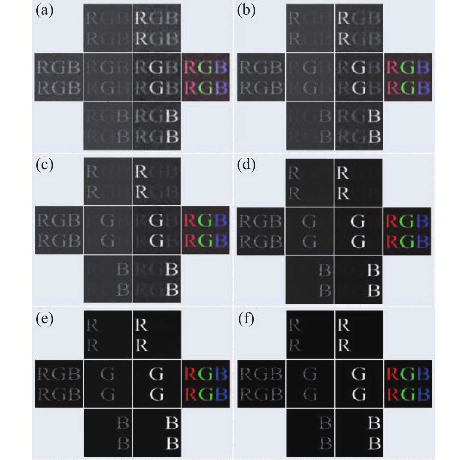
综合考虑光电探测器的响应时间与测量信号的信噪比,设置投影频率约为30 Hz,对于全采样256×256空间分辨率的图像,需要时间约为73 min (256×256×2/30),该时间主要受投影仪的投影频率限制,如果使用高速调制器件如数字微镜器件,其对二值化散斑的投影频率最大约为22.7 kHz,此时投影时间将大大降低,所需时间约为6 s。实验采用的光谱编码矩阵与仿真时相同,图像的复原过程也与仿真时的一样,即首先对实验获取的探测信号按照绝对值的大小进行排序,分别选取前6.25%、12.5%、25%、50%、75%和100%探测信号与对应的Hadamard图案进行迭代计算,然后将复原的混叠光谱图像分别与编码矩阵运算解调出三个通道的欠采样光谱通道图像,最后对解调出的三个图像分别应用组稀疏压缩感知算法重构全采样光谱分量图像,对其融合构成物体多光谱图像。相应的复原结果分别如图7(a)~(f)所示。从结果上可以看出,在6.25%采样率下,物体的混叠光谱图像(图7(a)第一列图像)已经呈现出来,然而重构的物体多光谱图像(图7(a)第四列图像)质量较差,未能分辨出物体各部分的颜色信息。随着采样率的提高,物体混叠光谱图像与多光谱图像质量随着增加。从50%、75%和100%采样率下复原的结果可以看出,已经较好地展现了物体的颜色信息。

图 7 (a)~(f)6.25%、12.5%、25%、50%、75%和100%采样率下的实验结果
Figure 7. (a)-(f) Experimental results under sample ratio of 6.25%, 12.5%, 25%, 50%, 75% and 100%
为对比验证所提方法的实验成像效果,通过将光谱编码矩阵去掉,采用传统方法分三次分别投影红光、绿光和蓝光Hadamard照明图案对成像物体进行调制,单像素探测器收集物体的反射信号,应用演化压缩技术分别复原三个通道的光谱图像,最后融合出物体多光谱图像。对比实验的系统配置与图5一样。图8为相应的复原结果,可以看出传统方法获取的结果与文中采用方法获取的结果相似,但是所提出的方法采样数只有传统方法的三分之一,大大降低了采集的数据量,提高了多光谱关联成像效率。

图 8 传统方法的成像结果。(a)~(f)对应了6.25%、12.5%、25%、50%、75%和100%采样率下的复原结果
Figure 8. Imaging results corresponding to traditional method. (a)-(f) Reconstruction under sample ratio of 6.25%, 12.5%, 25%, 50%, 75% and 100%
通过对光谱编码计算关联成像实验复原的多光谱图像与仿真的结果相比,发现实验复原的图像质量与仿真的图像质量有一定的差距,可能的原因如下:仿真的彩色物体是一个理想化的256×256分辨率的二值图像,而实验的成像物体是多灰度级的且分辨率高;此外,成像物体的反射率、探测器的光谱响应以及光源的稳定性等因素都会对实际的成像结果有较大影响。
-
文中提出光谱编码计算关联成像技术,使用单个点探测器实现彩色物体的多光谱成像。通过构造正交的二值化随机编码矩阵融合Hadamard基矩阵生成投影散斑,对宽带光源调制后照明成像物体,单像素探测器收集成像物体后向反射的信号。应用演化压缩技术从探测信号中复原成像物体的混叠光谱图像;鉴于编码矩阵的相互正交性质,通过混叠光谱图像与编码矩阵点乘运算分离出欠采样的光谱通道图像,然后对分离出的图像应用组稀疏压缩感知算法来重构全采样光谱通道图像,最后融合出目标物体的多光谱图像。通过理论分析、数值仿真和实验室实验三个方面对提出方法进行了阐述与评估验证。初步的实验结果表明,所提方法能够实现多光谱成像。所提方法简化了多光谱成像系统配置,降低了数据量。原理上采用的光谱编码方法可以扩展到更多的光谱通道,也可以应用在偏振成像、信息加密等领域。下一步拟通过深度学习方法来替代压缩感知优化算法,进一步提高光谱图像复原速度,提高光谱编码计算关联成像质量。
Study on spectral encoded computational ghost imaging
-
摘要: 现有的多光谱成像技术通常采用光学分光的方式,使用多个探测器对成像场景的光谱图像进行采集,导致现有成像系统复杂,数据量大、效率低。针对现有技术的不足,提出基于正交调制模式的光谱编码计算关联成像技术。通过正交光谱编码矩阵融合Hadamard基图案构造投影散斑对宽带光源进行调制,单像素探测器收集成像物体与调制光源相互作用后的反射信号;应用演化压缩技术复原成像物体的混叠光谱图像;利用编码矩阵的正交性质解码出欠采样的光谱分量图像,对分离出的图像应用组稀疏压缩感知算法重构全采样的光谱分量图像,最后融合出成像物体的多光谱图像。通过数值模拟与实验两方面验证了所提方法的高效性。所提的技术简化了多光谱关联成像系统,降低了数据量。光谱编码方法可以扩展到更多的光谱通道,也可以应用在偏振关联成像、信息加密等领域。Abstract: The existing multispectral imaging technologies usually utilize optical spectroscopy and multiple detectors to capture spectral images. These techniques suffer from complexity, a large amount of data and low efficiency. Addressing these deficiencies, in this paper, a spectral encoded computational ghost imaging technology based on orthogonal modulation model was proposed. The orthogonal spectral encoded matrices fused with Hadamard patterns were used to produce the illumination patterns that modulate the broadband light source. A single-pixel detector was utilized to collect the back-reflected signal from the imaging objects. The evolutionary compressive technology was applied to recover the mixed spectral image. The subsampled spectral channel images were obtained from the mixed spectral image by means of the orthogonality of the spectral encoded matrices. Then the group sparse compressed sensing algorithm was applied to reconstruct the full-sampling spectral channel images, which finally fused the multispectral image of the imaging object. The efficiency of the proposed method was verified by a numerical simulation and an experiment. The proposed technology simplifies the multispectral imaging configuration and greatly reduces the amount of data. The orthogonal spectral encoded strategy can extend to more spectral channels and also can be applied to polarization imaging, information encryption, and other many fields.
-
图 1 光谱编码计算关联技术的实现流程
Figure 1. Implementation process of spectal encoded computational ghost imaging technology
图 3 (a)按投影顺序记录的物体散射信号;(b)按信号绝对值从大到小排序的结果
Figure 3. (a) Corrected scattered singal under the projection order; (b) Result in descending order according to the absolute value
图 4 (a)~(f) 6.25%、12.5%、25%、50%、75%和100%采样率下的数值仿真结果
Figure 4. (a)-(f) Simulation results under sample ratio of 6.25%, 12.5%, 25%, 50%, 75% and 100%
图 5 光谱编码计算关联成像实验结构图
Figure 5. Structure diagram of spectral encoded computational ghost imaging
图 6 (a)投影仪投影红、绿和蓝光时的光谱;(b)探测器的光谱响应
Figure 6. (a) Red, green and blue spectal curves of the projector; (b) Spectral responsivity of the detector
图 7 (a)~(f)6.25%、12.5%、25%、50%、75%和100%采样率下的实验结果
Figure 7. (a)-(f) Experimental results under sample ratio of 6.25%, 12.5%, 25%, 50%, 75% and 100%
图 8 传统方法的成像结果。(a)~(f)对应了6.25%、12.5%、25%、50%、75%和100%采样率下的复原结果
Figure 8. Imaging results corresponding to traditional method. (a)-(f) Reconstruction under sample ratio of 6.25%, 12.5%, 25%, 50%, 75% and 100%
表 1 不同采样率下复原光谱分量与原图之间的均方差
Table 1. MSE of the reconstructed spectral channel images and the corresponding original images under different sample ratio (SR)
SR 6.25% 12.5% 25% 50% 75% 100% TR 9.37% 7.00% 4.76% 1.62% 0.63% 0.48% TG 6.57% 5.22% 3.81% 1.36% 0.62% 0.48% TB 6.97% 5.37% 4.17% 1.41% 0.64% 0.53%  下载: 导出CSV
表 2 不同采样率下复原图像与原图之间的峰值信噪比
Table 2. PSNR of the reconstructed spectral channel images and the corresponding original images under different sample ratio (SR)
SR 6.25% 12.5% 25% 50% 75% 100% TR 58.42 59.68 61.35 66.02 70.17 71.28 TG 59.95 60.95 62.32 66.80 70.24 71.30 TB 59.70 60.83 61.93 66.64 70.06 70.90
下载: 导出CSV
-
[1] Pittman T B, Shih Y H, Strekalov D V, et al. Optical imaging by means of 2-photon quantum entanglement [J]. Phys Rev A, 1995, 52(5): R3429-R3432. doi: 10.1103/PhysRevA.52.R3429 [2] Bennink R S, Bentley S J, Boyd R W. Two-photon coincidence imaging with a classical source [J]. Phys Rev Lett, 2002, 89: 113601. doi: 10.1103/PhysRevLett.89.113601 [3] Shapiro J H. Computational ghost imaging [J]. Phys Rev A, 2008, 78(6): 061802. doi: 10.1103/PhysRevA.78.061802 [4] Edgar M P, Gibson G M, Padgett M J. Principles and prospects for single-pixel imaging [J]. Nat Photonics, 2019, 13: 13-20. doi: 10.1038/s41566-018-0300-7 [5] Sun B, Edgar M P, Bowman R, et al. 3D computational imaging with single-pixel detectors [J]. Science, 2013, 340(6134): 844-847. doi: 10.1126/science.1234454 [6] Gibson G M, Sun B Q, Edgar M P, et al. Real-time imaging of methane gas leaks using a single-pixel camera [J]. Opt Express, 2017, 25(4): 2998-3005. doi: 10.1364/OE.25.002998 [7] Shi D F, Yin K X, Huang J, et al. Fast tracking of moving objects using single-pixel imaging [J]. Opt Commun, 2019, 440: 155-162. doi: 10.1016/j.optcom.2019.02.006 [8] Garini Y, Young I T, McNamara G. Spectral imaging: Principles and applications [J]. Cytom Part A, 2006, 69a: 735-747. doi: 10.1002/cyto.a.20311 [9] 字崇德, 李昀谦, 祖永祥, 等. 多传感器光谱视频成像系统中的图像对齐研究[J]. 红外与激光工程, 2019, 48(6): 0603019. doi: 10.3788/IRLA201948.0603019 Zi Chongde, Li Yunqian, Zu Yongxiang, et al. Research on image alignment in multi-sensor spectral video imaging system [J]. Infrared and Laser Engineering, 2019, 48(6): 0603019. (in Chinese) doi: 10.3788/IRLA201948.0603019 [10] Welsh S S, Edgar M P, Bowman R, et al. Fast full-color computational imaging with single-pixel detectors [J]. Optics Express, 2013, 21(20): 23068-23074. doi: 10.1364/OE.21.023068 [11] Huang J, Shi D F. Multispectral computational ghost imaging with multiplexed illumination [J]. J Optics-Uk, 2017, 19(7): 075701. doi: 10.1088/2040-8986/aa72ff [12] 时东锋, 黄见, 苑克娥, 等. 空间编码复用散斑多信息融合关联成像(特邀)[J]. 红外与激光工程, 2018, 47(5): 0502001. Shi Dongfeng, Huang Jian, Yuan ke'e, et al. Multi-information fused correlated imaging based on space-coded multiplexing speckles(Invited) [J]. Infrared and Laser Engineering, 2018, 47(5): 0502001. (in Chinese) [13] Zhang J, Zhao D, Gao W. Group-based sparse representation for image restoration [J]. IEEE Transactions on Image Processing, 2014, 23(8): 3336-3351. doi: 10.1109/TIP.2014.2323127 [14] Sun M J, Meng L T, Edgar M P, et al. A Russian Dolls ordering of the Hadamard basis for compressive single-pixel imaging [J]. Scientific Reports, 2017, 7(1): 3464. doi: 10.1038/s41598-017-03725-6 [15] 张家民, 时东锋, 黄见, 等. 前向调制散斑偏振关联成像技术研究[J]. 红外与激光工程, 2018, 47(10): 1041001. Zhang Jiamin, Shi Dongfeng, Huang Jian, et al. Polarization correlated imaging based on forward modulated speckles [J]. Infrared and Laser Engineering, 2018, 47(10): 1041001. (in Chinese) -

 点击查看大图

计量
- 文章访问数: 686
- HTML全文浏览量: 212
- PDF下载量: 131
- 被引次数: 0


