


-
射频激励二氧化碳激光器[1](RF-CO2激光器)以其高电光转换效率、连续输出、输出波段为大气窗口等优点而被应用于国防、通信、制造、医疗等领域。随着人工智能和大数据领域的快速兴起,RF-CO2激光器向智能化、集成化和数据可视化方向发展。
1979年,Laakmann等人首次描述了一种射频激励的封离型波导二氧化碳激光器[2]。1996年,日本东芝公司将电源和激光头融为一体[3],使得射频激励扩散冷却型板条二氧化碳激光器的功率突破1 kW。2009年,华中科技大学在大功率射频二氧化碳激光器的激励特性等方面做了深入研究,获得功率为30 kW、频率为83 MHz射频功率输出[4]。RF-CO2激光器是目前使用最频繁、技术最全面的板条激光器,国外Synrad公司和Coherent公司在技术领域占有绝对的领先地位[5]。国内RF-CO2激光器起步晚,与国外差距很大,其中华中科技大学、哈尔滨工业大学、北京理工大学和中国科学院取得了一定的成绩,主要研究领域有射频电源、阻抗匹配和功率控制等。与国外相比,国内的射频电源性能较差,匹配一般采用手动匹配,匹配精度和速度相对较慢。因此,目前国内的RF-CO2激光器主要依赖于进口,在关键技术和核心器件上仍然受制于国外厂商。
在RF-CO2激光器的开发过程中,负载复杂、与之匹配的射频电源一直是一个技术难点[6]。根据设计需求,射频电源通过匹配电路将功率持续稳定馈入激光器负载,然而由于匹配过程中动态阻抗参数不定[7],多是根据技术人员的经验手动调节,而且射频电源的数据采集和控制都是独立工作,不便实时监测和控制[8],因此总会有一定的射频功率反射回到功率管功放电路,产生自激振荡,导致功率管芯片烧损,甚至损坏激光器。虽然有研究者提出利用PID闭环控制[9]和BP神经网络[10]的方法来提高阻抗匹配精度和速度,但是依然无法避免射频反射导致功率管烧毁的问题。
为解决RF-CO2激光器射频电源和激光器负载匹配失调致使功率管烧毁的难题,文中从射频电源的监控和保护出发,设计了一套数据采集、自动保护的可视化RF-CO2激光器射频电源监控平台。经实验测试,该平台能够实现射频电源系统过压、过流、过热时的自动保护和故障报警[11-12],系统响应时间可缩短至微秒量级,远高于人工响应时间,能够有效避免功率管的烧损。通过系统的数据采集和分析功能可以有效监测记录射频电源工作状况,提高RF-CO2激光器开发效率。此外,系统预留了多个接口,具有并行开发多台RF-CO2激光器的潜力。
-
RF-CO2激光器正常工作时,由射频电源对输入信号进行功率放大,经过对应的匹配输出给激光器负载,如图1所示。

图 1 RF-CO2激光器结构示意图
Figure 1. Structure diagram of RF-CO2 laser
但射频电源系统不是绝对稳定的,由于射频能量的影响,传输线将不再遵循基尔霍夫理论。如图2所示,平行导线或电缆(图2(a))在这种情况下会等效成电容和电感(图2(b)),射频能量以电磁场的方式传输。

图 2 射频传输线等效电路
Figure 2. RF transmission line equivalent circuit
由于传输线的长度不同,转换成的阻抗大小也不尽相同,阻抗匹配网络也并非处于最佳匹配状态。于是,实际的RF-CO2激光器结构示意图可以等效成图3,整个RF-CO2激光器系统处于非稳定状态。
如图3所示,输入匹配与功率管功放以及输出匹配与功率管功放之间存在耦合关系,表现为RF信号源反射系数(
${\varGamma _{\rm{s}}}$ )、输入反射系数(${\varGamma _{{\rm{in}}}}$ )、输出反射系数(${\varGamma _{{\rm{out}}}}$ )、负载反射系数(${\varGamma _{\rm{l}}}$ )。图3中,
${\varGamma _{{\rm{in}}}}$ 和${\varGamma _{{\rm{out}}}}$ 分别反映输入匹配和输出匹配对功率管功放的反射功率大小。由于功率管功放本质上是一个工作在饱和状态的场效应管元件,其漏极电流和栅源电压间关系如图4所示。
图 3 RF-CO2激光器等效结构示意图
Figure 3. Schematic diagram of equivalent structure of RF-CO2 laser
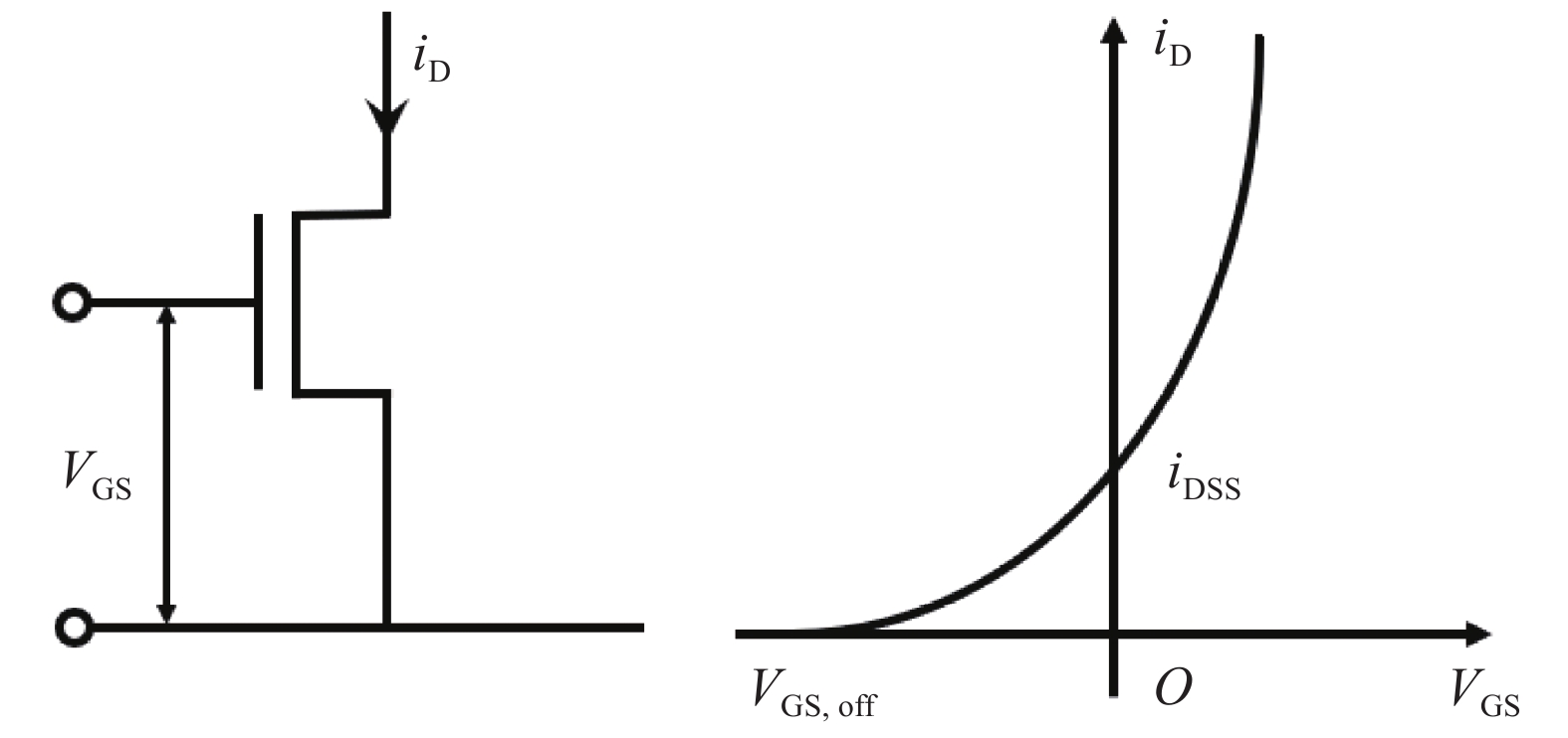
图 4 饱和区功率管的漏极电流与栅源电压关系
Figure 4. Relation between drain current and gate source voltage of power tube in saturated region
当反射功率过大时,功率管放大后的输出功率与反射功率相互作用形成自激振荡,产生一个较高的峰值电压,由于瞬间的峰值电压远大于功率管正常工作时的电压
${V_{\rm GS}}$ ,漏极电流${i_{\rm DS}}$ 激增,功率管就会被烧损。为保证射频电源正常运行,功率管不被烧毁,功率管需满足稳态放大要求[13]:
$$ \begin{split} \\ \left| {{\varGamma _{{\rm{in}}}}} \right| < 1 \end{split} $$ (1) $$ \left| {{\varGamma _{{\rm{out}}}}} \right| < 1 $$ (2) $$ \varGamma = {V_{\rm{r}}} /{{V_{{\rm{in}}}}} < 1 $$ (3) -
根据射频电源系统原理和功率管的特性,选择以下参量作为监控对象。
-
如图4所示,要保证功率管不被击穿,需要控制功放电路在稳定条件下工作,即
$\varGamma < 1$ ,根据$$ \varGamma = V_{\rm{r}}/V_{\rm{in}} $$ (4) 式中:
$\varGamma $ 为反射系数;${V_{\rm{r}}}$ 为反射电压;${V_{{\rm{in}}}}$ 为入射电压。要使得$\varGamma < 1$ ,即要求反射电压小于入射电压,且反射系数越小,匹配效果越好,射频电源也越稳定。反之,当
$\varGamma > 1$ ,即${V_{\rm{r}}} > {V_{{\rm{in}}}}$ 时,射频电源系统处于不稳定状态,此时极易产生自激振荡致使功率管被反向击穿。因此,入射电压、反射电压与反射系数作为重点监测对象。 -
反射信号过大时会与功率管的输出信号不断叠加,产生自激振荡现象,如图5所示。

图 5 自激振荡形成示意图
Figure 5. Schematic diagram of self-excited oscillation formation
自激振荡期间,功率管的漏极电流和温度激增,致使功率管熔断。而自激振荡产生到功率管熔断会经过一段时间
$\Delta {{t}}$ ,这段时间内功率管漏极电流和温度会有明显变化,因此,功率管的漏极电流和温度作为第二个监测对象。 -
根据设计原理和监测点的选取,将数据采集、自动保护和可视化技术与射频电源进行有效融合,建立RF-CO2激光器射频电源监控平台模型,如图6所示。

图 6 RF-CO2激光器射频电源监控平台
Figure 6. RF-CO2 laser RF power monitoring platform
整个平台系统分为三个层次:(a)应用层、(b)传输层和(c)设备层。
应用层是RF-CO2激光器射频电源监控平台软件:一方面实时监测RF-CO2激光器射频电源工作状态,存储数据信息,并以折线图直观地将数据变化趋势进行显示;另一方面,当参数异常时,下发保护指令到控制中心,关断射频电源。考虑到软件设计的可用性、可迁移性及可拓展性,应用层采用C#中的.NET Framework 技术。相比传统的VB和VC++开发技术,C#.NET具有跨平台、快响应和动态美的优点,开发的软件适用于各种windows系统。
传输层是由通信接口和控制中心组成的双向通信模块,主要用于实现应用层和设备层的数据传递和指令传输。为了避免射频的影响,保证数据可靠传输,传输层采用RSR232收发器搭建有线通信。为提高传出速率,减少CPU的功耗,采用DMA技术同时接收和发送,数据传输速度可高达11.5 Mbps,电流低至10 nA。
设备层是RF-CO2激光器射频电源监控平台的底层构架。该层以响应速度更快、处理能力更强的FLASH零等待状态和加密/HASH处理器STM32F407IGT单片机控制系统作为控制核心,一方面通过高速多通道A/D转换器与电压电流采样电路、温度传感器和功率采集模块进行连接,完成数据采集监测;另一方面控制保护电路和警报系统,实现及时响应[14]。
-
结合设计原理和平台设计结构,完成应用层、传输层和设备层的软件设计和电路搭建,其实物图如图7所示。

图 7 监控平台实物图
Figure 7. Physical picture of monitoring platform
平台采用型号为MRFE6VP61K25H系列的功率管作为主放大芯片设计射频电源,工作频率为81.36 MHz,其特性参数如表1所示。
表 1 功率管特性参数
Table 1. Power tube characteristic parameters
Characteristic Value VGS/V 10 IDS/A 30 Pout/W 1250 ${\eta _D}$ 74% GPS/dB 27 Frequency/MHz 81.36 Temperature/℃ −60-150 从表1中可知,功率管的反向击穿电压为10 V,漏极电流极限为30 A,正常工作温度范围为−60~150 ℃。为保证射频电源功率管处于正常工作范围,根据功率管的特征参数和稳定条件,将系统参数配置和阈值设定如表2所示。
表 2 系统配置参数
Table 2. System configuration parameters
Parameter Value Baud rate/bit 115200 Serial port COM5 Traffic rate/μs 0.5 Current threshold/A 13 Temperature threshold/℃ 100 Reflected voltage/V 5 Incident voltage/V 5 Reflection coefficient 1 其中反射系数
$\varGamma $ 为1,反射电压阈值${V_{{\rm{r}}th}}$ 为5 V,功率管漏极电流阈值${I_{Dth}}$ 为13 A,温度${T_{th}}$ 为100 ℃。启动RF-CO2激光器射频电源监控平台,监控平台软件界面显示如图8所示。
图 8 数据正常时监测结果
Figure 8. Monitoring results when data is normal
可以看到,左侧监测点数据显示区不断更新,图形区实时绘制当前反射电压、入射电压、漏极电流和功率管温度的变化曲线。此时采集到的入射电压为2.489 V,反射电压为2.216 V,漏极电流为8.997 A,芯片温度为19.343 ℃,输出功率为773.16 W。将测试数据与设定阈值参数进行比较得:
$$ {\varGamma }_{{\text{测}}}=\frac{{V}_{r}}{{V}_{in}}=\frac{{V}_{{\text{反测}}}}{{V}_{{\text{入测}}}}=\frac{2.216\;{\rm{V}}}{2.489\;{\rm{V}}}=0.89 < 1 $$ (5) $$ {V}_{r{\text{测}}}=2.216\;{\rm{V}} < 5\;{\rm{V}} $$ (6) $$ {I}_{d{\text{测}}}=8.997\;{\rm{A}} < 13\;{\rm{A}} $$ (7) $$ {T}_{{\text{测}}}=19.343\; {\text{℃}}<100 \;{\text{℃}} $$ (8) 所监测的数据均在正常范围,此时,射频电源处于正常状态,RF-CO2激光器射频电源监控平台的射频电源状态区绿灯亮起。
不断调节阻抗,测得警报触发、保护电路自动响应时的监控平台数据如图9所示。

图 9 数据异常时监测结果
Figure 9. Monitoring results when data is abnormal
此时,图形区的反射电压曲线超过了入射电压曲线,漏极电流曲线超过了设定的阈值界线,通过监测点数据区可以读出,此时漏极电流为13.94 A,反射电压为3.803 V,入射电压为3.690 V。可以看出,此时:
$$ {\varGamma }_{{\text{测}}}=\frac{{V}_{r}}{{V}_{in}}=\frac{{V}_{{\text{反测}}}}{{V}_{{\text{入测}}}}=\frac{3.803\;{\rm{V}}}{3.690\;{\rm{V}}}=1.031 > 1 $$ (9) 反射系数
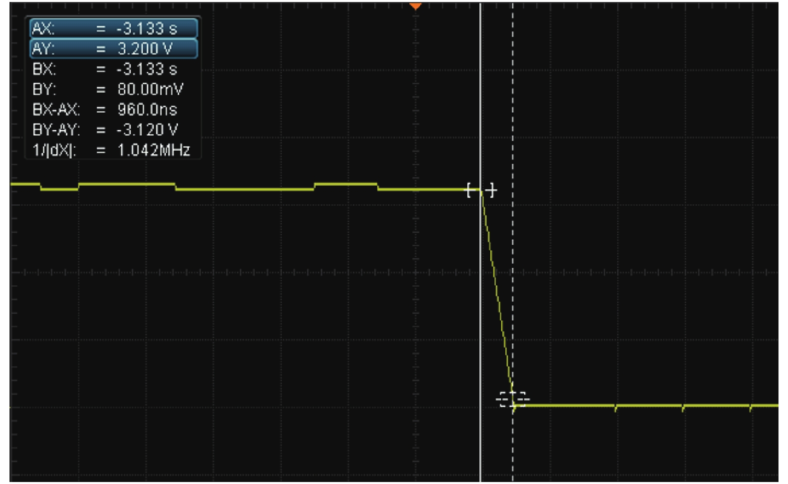
${\varGamma }_{{\text{测}}} > 1$ ,漏极电流${I}_{d{\text{测}}}=13.94\;{\rm{A}} > 13\;{\rm{A}}$ ,超过了设定的阈值界线,达到了射频电源不稳定的条件,监控平台自动响应保护电路,关断射频电源,其关断响应时间如图10所示。
图 10 关断响应时间
Figure 10. Time to turn off the response
从图10中可以看出,平台系统关断响应时间为
$ 0.96 $ μs,远高于人为反应的时间。检查射频电源功率管器件及相关电路器件,未出现烧毁情况。最后,利用该平台进行RF-CO2激光器开发调试,该平台能够自动处理数据,大幅提高RF-CO2激光器的开发效率。
-
文中基于RF-CO2激光器的开发调试过程,根据理论分析和计算,明确了需要采集的监测对象,设计了一套RF-CO2激光器射频电源监控平台。该平台以STM32开发板为控制核心,将射频电源的数据采集、控制模块与保护系统有效融合。经过分析和实验得出以下结论:
(1)该平台能够在RF-CO2激光器正常工作时,完成特定监测点的数据采集和实时的可视化动态显示;在当RF-CO2激光器射频电源数据出现异常时自动关断射频电源,完成系统保护,将几秒的人为响应时间缩短至
$ 0.96 $ μs的电路响应时间。(2)该平台实现了射频电源数据采集和自动保护控制的一体化,有效减少RF-CO2激光器开发调试过程中的射频功率管损耗,同时辅助工作人员观察和记录数据,大幅缩短了RF-CO2激光器的开发周期。
(3)该平台能够适用于多种功率需求的RF-CO2激光器开发调试。对于不同功率的RF-CO2激光器,只需通过该平台在调试过程中设置相应的阈值即可实现该RF-CO2激光器安全、快速的开发调试。
此外,平台还预留了冗余接口,具备多台RF-CO2激光器并行开发的潜力,后续笔者将继续该方向的研究。
RF-CO2 laser RF power supply monitoring platform
-
摘要: 射频电源是RF-CO2激光器中的一个重要部件。在开发一个新的RF-CO2激光器时,由于激光器负载和射频电源匹配失调,在调试过程中容易造成射频功放功率管击穿、烧损。为解决这一问题,设计了一套集数据采集、自动保护控制和可视化技术为一体的RF-CO2激光器射频电源监控平台。平台采用软件和硬件相结合的方式,在射频电源中嵌入控制模块,搭建数据采集系统和自动保护系统,并结合电路设计软件平台完成对射频电源的数据信息采集和保护控制。经过实验测试,平台可以有效避免射频电源功率管的损坏,实现射频电源的自动保护,并完成射频电源系统的数据采集和远程保护控制,缩短了RF-CO2激光器的调试周期,提高了整机的开发效率。Abstract: RF power supply is an important component in RF-CO2 laser. During the development of a new RF-CO2 laser, due to the mismatch between the laser load and the RF power supply, the power tube of the RF power amplifier is easy to break down and burn out in the debugging process. In order to solve this problem, a RF power supply monitoring platform for RF-CO2 laser, which integrated data acquisition, automatic protection control and visualization technology, was designed. The platform adopted a combination of software and hardware, a control module was embedded in the RF power supply, a data acquisition system and automatic protection system were set up, and combined with the circuit design software platform, the RF power supply data acquisition and protection control was completed. The experimental test shows that the platform can effectively avoid the damage of the power tube of the RF power supply, realize the automatic protection of the RF power supply, complete the data acquisition and remote protection control of the RF power supply system, shorten the debugging period of the RF-CO2 laser, and improve the development efficiency of the whole machine.
-
Key words:
- RF-CO2 laser /
- RF power supply /
- power monitoring /
- automatic protection
-
图 3 RF-CO2激光器等效结构示意图
Figure 3. Schematic diagram of equivalent structure of RF-CO2 laser
图 4 饱和区功率管的漏极电流与栅源电压关系
Figure 4. Relation between drain current and gate source voltage of power tube in saturated region
表 1 功率管特性参数
Table 1. Power tube characteristic parameters
Characteristic Value VGS/V 10 IDS/A 30 Pout/W 1250 ${\eta _D}$ 74% GPS/dB 27 Frequency/MHz 81.36 Temperature/℃ −60-150  下载: 导出CSV
表 2 系统配置参数
Table 2. System configuration parameters
Parameter Value Baud rate/bit 115200 Serial port COM5 Traffic rate/μs 0.5 Current threshold/A 13 Temperature threshold/℃ 100 Reflected voltage/V 5 Incident voltage/V 5 Reflection coefficient 1
下载: 导出CSV
-
[1] Wojaczck D A, Plinski E F, Witkowski J S. Thermodynamic and optical parameters of the RF pluse excited slab-waveguide CO2 laser [J]. Optica Applicata, 2005, 35(2): 215-224. [2] Kobayashi S, Terai K. 1 kW slab CO2 laser excited by a self-excited RF generator [C]//Proceedings of SPIE, 1997, 3092: 15-30. [3] Abram R, Hall D R. 2-didmensional waveguide CO2 laser arrays and beam reforming [C]//GCL/HPL’96, 1996: 25-30. [4] 柳娟.大功率射频二氧化碳激光器激励特性研究[D], 湖北: 华中科技大学, 2009. Liu Juan. Excitation characteristics of high power RF carbon dioxide laser[D]. Wuhan: Huazhong University of Science and Technology, 2009. (in Chinese) [5] 马科.气体放电激光高频电源控制系统的研究[D], 湖北: 华中科技大学, 2017. Ma Ke. Study on high frequency power supply control system of gas discharge laser[D]. Wuhan: Huazhong University of Science and Technology, 2017. (in Chinese) [6] J.卡尔·约瑟夫.射频电路设计[M].北京: 科学出版社, 2007, 3-1. Joseph J C. Radio Frequency Circuit Design [M]. He Jin, translated. Beijing: Science Press, 2007: 3-11. (in Chinese) [7] Cao Fengguang, Zhang Deling, Wang Xinbing, et al. Impedance matching study in RF power supply [J]. Applied Laser, 2005, 25(2): 102-136. (in Chinese) [8] Wang H Q, Meng F J, Guo L H, et al. High power TEA CO2 laser control system based on DSP [J]. Chinese Optics, 2020, 4(4): 411-417. (in Chinese) [9] 董维豪, 基于BP神经网络的自动阻抗匹配系统设计[D], 天津: 天津工业大学, 2019. Dong Weihao, Design of automatic impedance matching system based on BP neural network[D]. Tianjin: Tianjin University of Technology, 2019. (in Chinese) [10] Lin G J, Zhan T, Li J W, et al. Research and development of digital RF power supply network automatic matcher [J]. Technological Innovation and Application, 2016, 1: 116-117. (in Chinese) [11] Zhang K F, Jiang T, Shao L, et al. Research on LD precision temperature control based on a new fuzzy PID control unit [J]. Optical Precision Engineering, 2017, 25(3): 648-655. (in Chinese) doi: 10.3788/OPE.20172503.0648 [12] Zhang Long, Chen Jiansheng, Gao Jing, et al. Design of power supply and temperature control system for high-power semiconductor laser [J]. Infrared and Laser Engineering, 2018, 47(10): 1005003. (in Chinese) doi: 10.3788/IRLA201847.1005003 [13] Han Yue, Cong M F, Li Ke, et al. Stability analysis and design of radio frequency power amplifiers [J]. Microelectronics & Computers, 2018, 35(10): 72-74. (in Chinese) [14] Pan B B, Liang Xu, Pan N, et al. An excimer laser control system based on LabVIEW [J]. Chinese Optics, 2020, 44(3): 343-348. (in Chinese) -

 点击查看大图

计量
- 文章访问数: 353
- HTML全文浏览量: 79
- PDF下载量: 14
- 被引次数: 0


