


-
随着“工业4.0”和“中国制造2025”的提出,现代工业特别是大型装备制造业正在向信息化、智能化方向发展,大型装备的制造和装配对姿态精准测量提出了越来越高的要求[1]。
目前,国外激光跟踪姿态测量技术已推出商用产品。Leica公司的T-MAC姿态测量系统通过高精度高速变焦相机测量合作靶标上发光LED的位置信息配合激光跟踪仪得到被测物位姿[2-4]。美国的API利用STS (Smart Track Sensor)结合激光跟踪仪测量被测物位姿信息,STS内部配有两个编码器和一个水平传感器,两个编码器分别用于获取方位角和俯仰角,水平传感器用于获取横滚角[5-6]。FARO公司的超级6 DoF TrackArm测量系统通过关节臂完成被测物的姿态测量,关节臂由三个主要关节组成,测量时通过手臂关节处的光学编码器即可得到每个关节处的角度,将该数据传输到控制器转换为三维空间位姿即可完成被测物的姿态测量[7-8]。
国内基于激光跟踪设备的姿态测量技术起步较晚,主要集中在华中科技大学、天津大学、中国科学院微电子研究所、湖北工业大学等高校及研究所。华中科技大学[9-10]和天津大学[11-12]研究了盾构机施工中的姿态测量,以全站仪为基站,CCD相机内置于靶标内,通过CCD感知激光束投射点测量方位角和俯仰角,再利用倾角仪测量横滚角,该方法在实际使用中,由于倾角仪动态性能差,存在数据更新率低且测量范围有限等问题。湖北工业大学的闫坤[13]提出一种基于PSD和单目视觉相结合的姿态测量方法,该方法以全站仪为基站,CCD相机安装在全站仪同侧,采用纵向投影比法测量横滚角,在此基础上结合PSD对激光束投射点的测量信息得到方位角和俯仰角(以下简称纵向投影比法)。该方法克服了横滚角更新速率慢以及测量范围有限的问题,在远距离处具有较好的测量性能,但近距离处姿态测量精度不高,此外该方法未充分利用单目视觉姿态测量的冗余信息。
针对上述纵向投影比法中存在的问题,文中提出一种基于加权最小二乘数据融合的姿态测量方法(以下简称加权融合法)。该方法利用单目视觉近距离测量的高精度以及多传感姿态测量信息的冗余特性,将CCD测量信息与PSD测量信息相融合,以期能在有效测量范围内提升姿态角的测量精度。
-
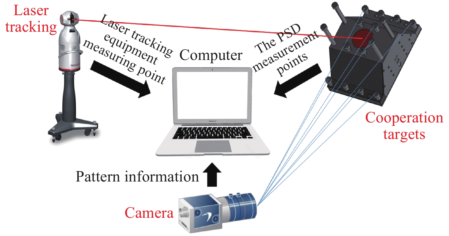
整个姿态测量系统由激光跟踪设备、相机、合作靶标以及上位机组成,如图1所示。其中激光跟踪设备与相机位置相对固定,合作靶标与被测物固定。
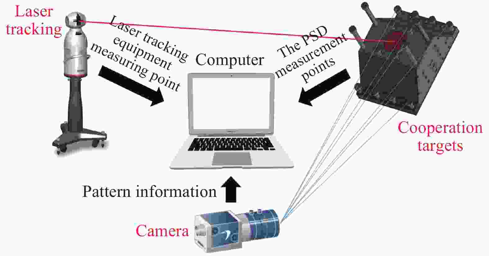
图 1 姿态测量系统组成
Figure 1. Composition of attitude measurement system
合作靶标由红外LED单元,切口角锥棱镜,二维PSD以及相应硬件电路组成。入射激光通过角锥棱镜切口部分入射到二维PSD上,得到PSD测点,结合激光跟踪设备测点以及图像信息完成姿态角解算。
-
对测量系统所用坐标系进行定义,如图2所示。相机坐标系OC-XCYCZC原点位于相机光心,定义光轴方向为ZC轴正向,XC轴和YC轴与像平面平行;激光跟踪设备坐标系OL-XLYLZL原点位于激光跟踪设备激光头,定义水平码盘0°为ZL轴正向,XL轴与水平码盘垂直,YL轴由右手定则确定;PSD坐标系OD-XDYD原点位于感光面正中心,XD轴和YD轴与感光面边线平行;合作靶标坐标系OT-XTYTZT原点位于角锥棱镜切口中心,定义垂直切面且穿过二维PSD坐标系原点OD方向为ZT正方向,XT轴和YT轴分别与XD轴和YD轴平行。棱镜切口与二维PSD间隔为OTOD,长度为h。

图 2 姿态测量系统坐标系定义
Figure 2. Definition of the coordinate system of the attitude measurement system
-
设相机与合作靶标之间的旋转矩阵为
$ {\boldsymbol{R}}_T^C $ ,相机与激光跟踪设备之间的旋转矩阵为$ {\boldsymbol{R}}_L^C $ ,激光跟踪设备坐标系下光束向量为$ \mathop {{{\boldsymbol{L}}_{{O_L}}}}\limits^ \to $ ,靶标坐标系下光束向量为$ \mathop {{{\boldsymbol{L}}_{{O_T}}}}\limits^ \to $ ,则存在关系:$$ {\boldsymbol{R}}_T^C \cdot \frac{{\mathop {{{\boldsymbol{L}}_{{O_T}}}}\limits^ \to }}{{\left\| {\mathop {{{\boldsymbol{L}}_{{O_T}}}}\limits^ \to } \right\|}} = {\boldsymbol{R}}_L^C \cdot \frac{{\mathop {{{\boldsymbol{L}}_{{O_L}}}}\limits^ \to }}{{\left\| {\mathop {{{\boldsymbol{L}}_{{O_L}}}}\limits^ \to } \right\|}} $$ (1) 定义姿态角旋转方向为Y-X-Z。假设相机坐标系下靶标旋转角度分别为方位角φ、俯仰角θ、横滚角
$ \phi$ ,则有:$$ \begin{split} {\boldsymbol{R}}_T^C {\text{ = }} \left[ {\begin{array}{*{20}{c}} {\cos \theta }& 0 &{\sin \theta } \\ 0& 1 &0 \\ { - \sin \theta }& 0 &{\cos \theta } \end{array}} \right]\left[ {\begin{array}{*{20}{c}} 1& 0 &0 \\ 0& {\cos \varphi } &{ - \sin \varphi } \\ 0& {\sin \varphi } &{\cos \varphi } \end{array}} \right]\left[ {\begin{array}{*{20}{c}} {\cos \phi }& { - \sin \phi } &0 \\ {\sin \phi }& {\cos \phi } &0 \\ 0& 0 &1 \end{array}} \right] \end{split} $$ (2) 相机与激光跟踪设备的位置相对固定,因此矩阵
$ {\boldsymbol{R}}_L^C $ 可通过外部标定提前得知。由激光跟踪设备完成对角锥棱镜顶点位置的测量,即得到激光跟踪设备坐标系下光束向量$ \mathop {{{\boldsymbol{L}}_{{O_L}}}}\limits^ \to $ 。通过PSD测量光斑位置结合间距h得到靶标坐标系下光斑坐标,即得到靶标坐标系下光束向量$ \mathop {{{\boldsymbol{L}}_{{O_T}}}}\limits^ \to $ 。通过参考文献[14]中的单目视觉法可解算得到方位角
$ {\varphi _1} $ ,俯仰角$ {\theta _1} $ ,横滚角$ {\phi _1} $ ,将横滚角$ {\phi _1} $ 作为已知量代入公式(1),结合光束向量在不同坐标系下的唯一性可计算得到方位角${\varphi _2}$ ,俯仰角$ {\theta _2} $ ,因此方位角和俯仰角存在冗余,下节将详细阐述冗余信息的融合方法。 -
设Y为n维测量向量,x为一维待测向量,即测量真值,H为已知n维常向量,e为n维测量噪声向量,则存在关系:
$$ \boldsymbol{Y}=\boldsymbol{H} x+\boldsymbol{e} $$ (3) 加权最小二乘法估计的准则是使加权误差平方和
${J_w}(\hat x){\text{ = }}{(\boldsymbol{Y} - \boldsymbol{H}\hat x)^{\text{T}}}\boldsymbol{W}(\boldsymbol{Y} - \boldsymbol{H}\hat x)$ 取最小值,其中,$\hat x$ 的是真值x的估计值,$\boldsymbol{W}$ 是一个正定对角加权阵,$\boldsymbol{W} = {\text{diag}}\left( {{w_1}{w_2} \cdots {w_n}} \right)$ 。对其求偏导并令偏导数为零得到$\hat x$ 的最小二乘估计:$$ \hat x = {\left( {{{\boldsymbol{H}}^{\text{T}}}{\boldsymbol{WH}}} \right)^{ - 1}}{{\boldsymbol{H}}^{\text{T}}}{\boldsymbol{WY}} = \frac{{\sum\limits_{i = 1}^n {{w_i}} {y_i}}}{{\sum\limits_{i = 1}^n {{w_i}} }} $$ (4) 对各测量值中的测量噪声做如下假设:(1)各测量值中的测量噪声服从正态分布的高斯白噪声且相互独立;(2)利用概率论知识可以证明:多个相互独立的随机变量相加的和接近正态分布, 因此测量噪声的分布也是正态分布的。所以有:
$$ E\left[ {{e_i}} \right] = 0 $$ (5) $$ E\left[ {e_i^2} \right] = E\left[ {{{\left( {x - {y_i}} \right)}^2}} \right] = \sigma _i^2 $$ (6) 式中:
$\sigma _i^2$ 为第i个测量值的测量方差。设$\mathop x\limits^ \sim $ 为估计误差,则有:$$ \mathop x\limits^ \sim = E\left[ {{{(x - \hat x)}^2}} \right] = E\left\{ {\sum\limits_i^n {\left[ {{{\left( {\dfrac{{{w_i}}}{{\displaystyle\sum\limits_{i = 1}^n {{w_i}} }}} \right)}^2}{{\left( {x - {y_i}} \right)}^2}} \right]} } \right\} $$ (7) 各个测量值噪声之间相互独立,因此有:
$$ E\left[ {(x - {y_i})(x - {y_i})} \right] = E[(x - {y_i})] \cdot E\left[(x - {y_i})\right] $$ (8) 由公式(7)、(8)可得:
$$ E\left[ {{{(x - \hat x)}^2}} \right] = \sum\limits_{i = 1}^n {{{\left( {\dfrac{{{w_i}}}{{\displaystyle\sum\limits_{i = 1}^n {{w_i}} }}} \right)}^2}} \sigma _i^2 $$ (9) 对公式(9)求极小值,取
${w_i}$ 的偏导数并令其为零,则有:$$ {w_i} = \frac{1}{{\sigma _i^2}},\;\;\;{\kern 1pt} i = 1,2, \cdots ,n $$ (10) $$ E\left[ {{{(x - \hat x)}^2}} \right] = \dfrac{1}{{\displaystyle\sum\limits_{i = 1}^n {\dfrac{1}{{\sigma _i^2}}} }} $$ (11) 由公式(11)可看出,采用加权融合的估计方差比任何一个测量值的测量方差都小。当以算术平均作为状态的估计时,其估计方差为
$\dfrac{1}{{{n^2}}}\displaystyle\sum\limits_{i = 1}^n {\sigma _i^2}$ ,进而证明加权融合的效果要优于算术平均估计。进一步地,可以得到测量真值x的估计量$\hat x$ 。$$ \hat x = {\left( {{{\boldsymbol{H}}^{\text{T}}}{\boldsymbol{WH}}} \right)^{ - 1}}{{\boldsymbol{H}}^{\text{T}}}{\boldsymbol{WY}} = \frac{{\displaystyle\sum\limits_{i = 1}^n {\dfrac{{{y_i}}}{{\sigma _i^2}}} }}{{\displaystyle\sum\limits_{i = 1}^n {\dfrac{1}{{\sigma _i^2}}} }} $$ (12) 由公式(12)可知,各个测量值的权重系数由其测量方差决定。可以采取预先标定的方式,通过实验得到
$ {\varphi _1} $ 、${\varphi _2}$ 、$ {\theta _1} $ 和$ {\theta _2} $ 的方差${S_{{\varphi _1}}}$ 、${S_{{\varphi _2}}}$ 、${S_{{\theta _1}}}$ 和${S_{{\theta _2}}}$ ,根据方差倒数确定权重系数。则有:$$ \varphi = \left(\dfrac{{{\varphi _1}}}{{{S_{{\varphi _1}}}}} + \dfrac{{{\varphi _2}}}{{{S_{{\varphi _2}}}}}\right)\dfrac{{{S_{{\varphi _1}}}{S_{{\varphi _2}}}}}{{{S_{{\varphi _1}}}{\text{ + }}{S_{{\varphi _2}}}}} $$ (13) $$ \theta = \left(\dfrac{{{\theta _1}}}{{{S_{{\theta _1}}}}} + \dfrac{{{\theta _2}}}{{{S_{{\theta _2}}}}}\right)\dfrac{{{S_{{\theta _1}}}{S_{{\theta _2}}}}}{{{S_{{\theta _1}}}{\text{ + }}{S_{{\theta _2}}}}} $$ (14) 式中:ϕ,θ为融合之后的方位角与俯仰角。横滚角φ取单目视觉解算的横滚角
$ {\phi _1} $ 。根据姿态角(ϕ,θ,φ)可得相机与合作靶标之间的旋转矩阵${\boldsymbol{R}}_T^C$ 。由旋转矩阵的性质,可知激光跟踪设备与靶标之间的旋转矩阵
$ {\boldsymbol{R}}_T^L $ 为:$$ {\boldsymbol{R}}_T^L{\text{ = (}}{\boldsymbol{R}}_L^C{)^{ - 1}} \cdot {\boldsymbol{R}}_T^C $$ (15) 将
$ {\boldsymbol{R}}_T^L $ 表示为3×3的矩阵形式,令${\boldsymbol{R}}_T^L = \left[ {\begin{array}{*{20}{c}} {{r_{11}}} & {{r_{12}}} & {{r_{13}}}\\ {{r_{21}}} & {{r_{22}}} & {{r_{23}}}\\ {{r_{31}}} & {{r_{32}}} & {{r_{33}}} \end{array}} \right]$ ,结合公式(2)得到最终激光跟踪设备坐标系下靶标姿态角方位角α、俯仰角β、横滚角γ。$$ \alpha = - \arcsin ({r_{23}}) $$ (16) $$ \beta = \arctan \left(\dfrac{{{r_{13}}}}{{{r_{33}}}}\right) $$ (17) $$ \gamma = \arctan \left(\dfrac{{{r_{21}}}}{{{r_{22}}}}\right) $$ (18) -
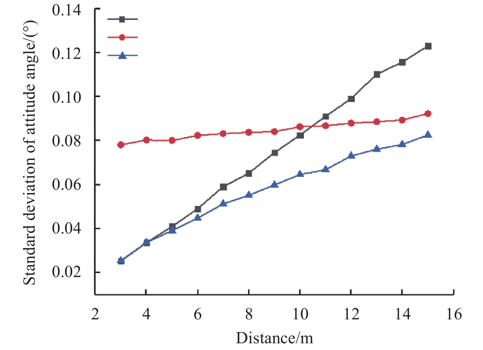
运用MATLAB对上述方法进行蒙特卡洛仿真分析。仿真条件如下:激光跟踪设备测点误差为2 mm,相机图像提取误差为0.1 pixel,二维PSD测点误差为0.01 mm,角锥棱镜与二维PSD安装间距误差为0.01 mm。对预设姿态角[0°, 0°, 0°]下的靶标进行姿态测量仿真,测量距离3~15 m,测量步长1 m,共13个位置,取姿态角的加权平均标准差作为误差评价指标。计算公式表示为:
$$ \sigma = \sqrt {\frac{{{S_\alpha } + {S_\beta } + {S_\gamma }}}{3}} $$ (19) 式中:Sα、Sβ、Sγ分别为方位角、俯仰角和横滚角方差,将文中加权融合法与数据融合前的单目视觉法,纵向投影比法对比。仿真结果如图3所示。

图 3 姿态角测量方法仿真对比
Figure 3. Simulation comparison of attitude angle measurement methods
仿真结果表明,在测量距离为3~10 m时,单目视觉法测量精度高于纵向投影比法;当测量距离为11~15 m时,纵向投影比法测量精度高于单目视觉法;在测量距离为3~15 m时,加权融合法测量精度均高于单目视觉法和纵向投影比法。
从测量精度随距离变化的趋势来看,单目视觉法测量精度随距离线性下降;纵向投影比法测量精度随距离变化较小;加权融合法测量精度虽随距离增加有所下降,但精度下降速度较单目视觉法和纵向投影比法缓慢。
-
针对上述姿态测量方法搭建了以全站仪、工业CCD、合作靶标和上位机为核心的实验平台,如图4所示。

图 4 姿态测量系统实验平台
Figure 4. Attitude measurement system experimental platform
全站仪选用Leica TM50,测量距离1.5~2000 m,测量精度2 mm;相机选用Basler acA2500-20 gm工业相机,分辨率2590×2048,像元尺寸4.8 μm,镜头焦距12 mm;二维PSD选用深圳达瑞鑫光电的DRX-PSD-OA02-X,感光尺寸15 mm×15 mm,分辨率0.01 mm,合作靶标采用立体式设计,表面布有共计16个高度不同LED主动发光式特征点。
为验证姿态测量的精度,利用二维精密转台旋转角度作为角度基准对姿态测量精度进行评定。二维精密转台方位角测量范围为0°~360°,俯仰角测量范围为50°~330°,角度测量精度为2"。由于二维精密转台只能在方位角和俯仰角方向上转动,且受限于靶标安装位置俯仰角转动范围有限,故实验主要为方位角测量数据。由仿真分析可知,方位角与俯仰角测量精度相近,横滚角精度较方位角和俯仰角测角精度高[15]。因此将方位角的测量精度作为整个姿态测量系统的精度评定标准。
-
在上述实验平台上对姿态测量精度进行评定,步骤如下:
(1)激光跟踪设备与相机固定安装在预设位置,靶标安装在二维精密转台上;
(2)将激光跟踪设备坐标系与转台坐标系配准;
(3)控制二维精密转台转动,方位角转动范围−30°~30°,每次转动10°,将方位角测量结果与转台转动角度值对比,得到方位角测量偏差;
(4)改变测量距离,测量距离范围3~8 m,步长为1 m。重复步骤(3),得到不同距离下的方位角测量偏差。
-
根据上述实验步骤,得到方位角测量偏差,见表1。
表 1 方位角测量偏差
Table 1. Azimuth measurement deviation
Distance/m Yaw/(°) −30 −20 −10 0 10 20 30 3 −0.17 0.26 0.43 0.54 0.72 0.50 0.37 4 −0.53 0.49 0.65 1.12 0.79 0.71 0.58 5 0.76 1.53 1.25 0.49 −0.17 0.68 −0.56 6 1.25 −0.79 −0.38 0.92 1.91 1.56 −0.64 7 −1.03 1.62 1.98 −0.41 0.87 2.25 −0.78 8 2.23 2.58 −1.81 −1.09 1.56 0.94 −0.95 由表1可知,在[−30°, 30°]的角度测量范围内,姿态测量系统在测量距离为3 m时最大的偏差绝对值为0.72°,测量距离为5 m时最大的偏差绝对值为1.53°,测量距离为8 m时最大的偏差绝对值为2.58°。采用标准差作为姿态角精度评定标准,可得到姿态测量系统在测量距离为3 m时,姿态测量精度为0.28°,测量距离为5 m时,姿态测量精度为0.74°,测量距离为8 m时,姿态测量精度为1.76°。
分别采用单目视觉法和加权融合法在不同距离处进行姿态测量,并采用上述标准差评定方法对测角精度进行对比分析,结果如表2所示。
由表2可知,加权融合法与单目视觉法相比,测角精度有所提升,当测量距离为3 m时,测量精度提升了6.7%,测量距离为8 m时,测量精度提升了18.8%。由参考文献[16]知纵向投影比法在测量距离2.5 m处,姿态角测量范围为[−20°, 20°]时,姿态角最大偏差在2°内。因此在测量距离为3~8 m时,相较于单目视觉法和纵向投影比法,文中提出的加权融合法具有更高的测量精度。
表 2 单目视觉法与加权融合法测角精度对比
Table 2. Comparison of angle measurement accuracy between monocular vision method and weighted fusion method
Distance/m Standard deviation of attitude angle/(°) Monocular vision method Weighted fusion method 3 0.30 0.28 4 0.62 0.51 5 0.78 0.74 6 1.41 1.12 7 1.63 1.37 8 2.17 1.76 -
针对大型设备制造业中对于姿态精准测量的需求,文中提出了一种基于加权最小二乘的激光跟踪姿态测量数据融合方法。该方法充分利用单目视觉近距离测量横滚角的高分辨率、PSD远距离测量方位角和俯仰角的高灵敏度以及多维冗余数据的利用,提升了系统姿态测量的性能。实验结果表明,在[−30°, 30°]的角度测量范围内,测量距离为3 m时,姿态测量精度为0.28°,测量距离为8 m时,姿态测量精度为1.76°,相比于单目视觉法,姿态角测量精度在3 m时提升了6.7%,在8 m时提升了18.8%。文中提出的加权最小二乘法对激光跟踪姿态测量精度的提升具有显著的效果。
Laser tracking attitude angle measurement method based on weighted least squares
-
摘要: 针对现代工业生产中大型装备的生产、制造和装配对于姿态精准测量提出的需求,提出了一种基于加权最小二乘的激光跟踪姿态角测量方法。首先,阐述了姿态测量系统的组成,并对姿态测量系统中使用的坐标系进行定义;其次,建立了姿态测量数学模型,在此基础上利用加权最小二乘法对冗余角度信息进行数据融合,并采用蒙特卡洛法对融合方法进行了仿真分析;最后,搭建了姿态测量实验平台,利用精密二维转台对系统姿态角测量精度进行了评定。实验结果表明:在[−30°, 30°]角度范围内,测量距离为3 m时姿态角测量精度为0.28°,测量距离为8 m时姿态角测量精度为1.76°;与单目视觉法相比,姿态角测量精度在3 m时提升了6.7%,在8 m时提升了18.8%。文中提出的数据融合方法对姿态角测量精度的提升具有较好效果。Abstract: In response to the demand for precise attitude measurement in the production, manufacturing and assembly of large-scale equipment in modern industrial production, a laser tracking attitude angle measurement method based on weighted least squares was proposed. Firstly, the composition of the attitude measurement system was explained, and the coordinate system used in the attitude measurement system was defined; Secondly, the mathematical model of attitude measurement was established, and on this basis, the redundant angle information was data fused using the weighted least square method. The Monte Carlo method was used to simulate and analyze the fusion method; Finally, an attitude measurement experimental platform was built, and the precision of the system’s attitude angle measurement accuracy was evaluated using a precision two-dimensional turntable. The experimental results show that within the angle range of [−30°, 30°], the attitude angle measurement accuracy is 0.28° when the measurement distance is 3 m, and the attitude angle measurement accuracy is 1.76° when the measurement distance is 8 m. Compared with the monocular vision method, attitude angle measurement accuracy increased by 6.7% at 3 m and 18.8% at 8 m. The poposed data fusion method has a good effect on improving the accuracy of attitude angle measurement.
-
Key words:
- attitude measurement /
- weighted least squares /
- monocular vision /
- laser tracking
-
图 2 姿态测量系统坐标系定义
Figure 2. Definition of the coordinate system of the attitude measurement system
表 1 方位角测量偏差
Table 1. Azimuth measurement deviation
Distance/m Yaw/(°) −30 −20 −10 0 10 20 30 3 −0.17 0.26 0.43 0.54 0.72 0.50 0.37 4 −0.53 0.49 0.65 1.12 0.79 0.71 0.58 5 0.76 1.53 1.25 0.49 −0.17 0.68 −0.56 6 1.25 −0.79 −0.38 0.92 1.91 1.56 −0.64 7 −1.03 1.62 1.98 −0.41 0.87 2.25 −0.78 8 2.23 2.58 −1.81 −1.09 1.56 0.94 −0.95  下载: 导出CSV
表 2 单目视觉法与加权融合法测角精度对比
Table 2. Comparison of angle measurement accuracy between monocular vision method and weighted fusion method
Distance/m Standard deviation of attitude angle/(°) Monocular vision method Weighted fusion method 3 0.30 0.28 4 0.62 0.51 5 0.78 0.74 6 1.41 1.12 7 1.63 1.37 8 2.17 1.76
下载: 导出CSV
-
[1] Yang Zhen, Shen Yue, Deng Yong, et al. Rapid cubic prism collimation and attitude measurement method based on laser tracker [J]. Infrared and Laser Engineering, 2018, 47(10): 1017001. (in Chinese) [2] Peng Jingfu, Ye Dingye, Zhang Gang, et al. An enhanced kinematic model for calibration of robotic machining systems with parallelogram mechanisms [J]. Robotics and Computer Integrated Manufacturing, 2019, 59: 92-103. doi: 10.1016/j.rcim.2019.03.008 [3] Guo Zhili, Fu Haizhang, Yi Lifu, et al. Kinematic calibration of serial robot using dual quaternions [J]. The Industrial Robot, 2019, 46(2): 247-258. doi: 10.1108/IR-10-2018-0221 [4] Liu Kai. Application of leica absolute laser tracker in calibration and inspection of industrial robot [J]. Intelligent Manufacturing, 2018(5): 43-46. (in Chinese) [5] Zhang Hongbing, Lian Zhaobin, Cheng Qiang, et al. Repeated positioning accuracy measurement of industrial robot based on API laser tracker [J]. Machinery Manufacturing, 2019, 57(5): 105-106. (in Chinese) [6] API. Application of API T3 laser tracker and I360 composite intelligent probe in wing assembly engineering [J]. Aeronau Tical Manufacturing Technology, 2011(8): 105. (in Chinese) [7] Guo Yuanjun, Zhou Xiang, Zhong Zhenrong, et al. Application of FARO arm in wall thickness measurement [J]. Aerospace Manufacturing Technology, 2020, 6: 60-62. [8] Faro. The all-new Faro edge scanarm HD measuring arm [J]. Mechanical and Electrical Engineering Technology, 2014, 43(9): 8. (in Chinese) [9] Pan Minghua, Wen Xiangwen, Zhu Guoli. Design of combination measurement system for pitching angles [J]. Optics and Precision Engineering, 2011, 19(3): 598-604. (in Chinese) doi: 10.3788/OPE.20111903.0598 [10] Zhu Guoli, Chen Peidong. Center location algorithm based on edge detection in shield attitude measurement [J]. Mechanical Engineering & Automation, 2014(5): 39-41. (in Chinese) [11] Guo Qingyao, Lin Jiarui, Ren Yongjie, et al. Combined pose measurement method based on laser target and strapdown inertial navigation system [J]. Laser Optoelectronics Progress, 2018, 55(1): 011202. (in Chinese) [12] He Feiyan, Lin Jiarui, Gao Yang, et al. Optimized pose measurement system combining monocular vision with inclinometer sensors [J]. Acta Optica Sinica, 2016, 36(12): 1215002. (in Chinese) [13] Yan Kun. Research on laser tracking attitude measurement method based on PSD and monocular vision[D]. Wuhan: HuBei University of Technology, 2020. (in Chinese) [14] Lao Dabao, Zhang Huijuan, Xiong Zhi, et al. Automatic measurement method of attitude based on monocular vision [J]. Acta Photonica Sinica, 2019, 48(3): 0315001. (in Chinese) [15] Wen Zhuoman, Wang Yanjie, Di Nan, et al. Fast recognition of cooperative target used for position and orientation measurement of space station’s robot arm [J]. Acta Aeronautica et Astronautica Sinia, 2015, 36(4): 1330-1338. (in Chinese) [16] Zhang Liugang, Xiong Zhi, Feng Wei, et al. Laser tracking attitude angle measurement method based on vision and laser collimation [J]. Chinese Journal of Scientific Instrument, 2020, 41(8): 30-36. (in Chinese) -

 点击查看大图
图(4) / 表(2)
计量
- 文章访问数: 254
- HTML全文浏览量: 58
- PDF下载量: 29
- 被引次数: 0


