


-
运动目标轨迹重构技术广泛运用于航天探测、自动驾驶、人机交互等领域[1]。目前主流的轨迹重构算法主要依靠激光雷达、深度相机、毫米波雷达等方式获取图像或深度信息,在使用场景与探测距离方面具有一定的局限性[2]。红外热成像仪作为一种被动式的红外热辐射传感器,具备在低照度的夜间和复杂多变气候条件下的工作能力,不受尘埃、浓雾、烟幕等环境的影响,且有一定的隐蔽性,广泛应用于火灾防治、军事侦察、自动驾驶等领域[3]。将红外热成像的技术引入运动目标三维轨迹重构中将有效地提高轨迹重构的适用性,拓宽使用场景与探测范围。此外,相较于定基线双目摄像头视差法测距,结合自身运动信息的移动式单目(红外)摄像头可以拥有灵活的视角及实时可变的等效基线,可以通过平滑约束或轨迹视线交汇等算法实现远距离运动目标的轨迹重构。
验证红外热成像中运动目标轨迹重构算法的有效性需要提供大量的红外目标图像来进行测试与训练,而现有的具备物理引擎的动态仿真平台大都不原生支持红外图像的仿真功能,通常需要使用者编写红外成像仿真插件来完成红外成像的仿真模拟。红外成像的仿真方式主要包括数值计算、图像模拟以及物理建模这三种[4],其中数值计算方式采用简化模型,只关注目标的整体辐射特性;图像模拟的方式聚焦于目标的图形或纹理特征,通常不建立目标的实际辐射模型;物理建模方式则实现了对整个仿真环境的物理建模,采用数值计算的方式对辐射传输过程进行数值计算,实现比较完善的高精度红外成像仿真。通过编写相应的红外仿真插件,可以生成可供轨迹重构动态仿真的热成像数据,解决现有CMU、EuRoc等开源数据集样本数量少、运动模型有限以及部分信息缺失等问题,充分验证相关算法的有效性与实际性能。
因此,鉴于目前国内外此类综合轨迹重构动态仿真平台的缺失,文中提出了一种利用红外热成像进行运动目标三维轨迹重构的方法,并搭建了一套虚拟红外图像生成与动态轨迹重构的仿真平台,可以实现不同场景下的红外运动目标识别追踪与轨迹重构,可实时输出构建误差、运行效率等性能指标信息。
-
红外成像通过热红外敏感CCD接收特定波长范围的红外辐射,并通过光电转换、信号处理等手段对物体进行成像,能反映出物体表面的温度场。在热成像系统中,每个像素代表一个特定的温度数据点,当热传感器检测到相应点热辐射强度的变化时,它将通过调整像素的色彩或灰度来表征这种变化。在文中的仿真环境中,使用COLLADA模型将材质的辐射特性与反射特性按照预定值进行赋值,之后在单目相机模型中获取相关特征,按照线性量化的方式将其解码并转化为灰度值,实现红外成像仿真。具体的实现步骤如下。
首先,由普朗克公式得:
$$ E={\varepsilon }_{0}\cdot {\int }_{{\lambda }_{1}}^{{\lambda }_{2}}\frac{{C}_{1}}{{\lambda }^{5}}{{\rm{e}}}^{\frac{-{C}_{2}}{\lambda T}}{\rm{d}}\lambda $$ (1) 式中:$ E $为探测到的红外辐射强度;$ {C}_{1} $、$ {C}_{2} $分别为第一辐射常数与第二辐射常数[5];$ {\lambda }_{1} $~$ {\lambda }_{2} $代表红外探测的波长范围。将预设的最高温度$ {T}_{\mathrm{m}\mathrm{a}\mathrm{x}} $与最低温度$ {T}_{\mathrm{m}\mathrm{i}\mathrm{n}} $代入公式(1),可以求得最大辐射强度$ {E}_{\mathrm{m}\mathrm{a}\mathrm{x}} $与最小辐射强度$ {E}_{\mathrm{m}\mathrm{i}\mathrm{n}} $,据此,得到虚拟红外热成像的灰度值换算结果:
$$ g(x,y)=\frac{E-{E}_{\mathrm{m}\mathrm{i}\mathrm{n}}}{{E}_{\mathrm{m}\mathrm{a}\mathrm{x}}-{E}_{\mathrm{m}\mathrm{i}\mathrm{n}}}\times 255 $$ (2) 式中:(x,y)代表投影点在相机坐标系中的坐标,为了加快运行速度,灰度值选取为8位,其取值范围为[0,255]。在仿真模型中,只需要按照给定的物体温度场模型将辐射强度E转化为可通过单目成像传感器获得的数据即可实现模拟红外热成像[6]。文中为了简化仿真计算的复杂性,将目标模型的反射系数设置为最大,将其余模型的反射系数赋予一个较低的数值,并将其颜色通道中的R值依照预定温度场的分布进行线性赋值。此时,在该仿真环境中,稳定光源下物体的成像结果与真实的热成像模型下基本一致,可用于进一步的动态仿真中。
-
针对红外图像的生成,采用类似信源编码的方法将红外热辐射信息按照一定的对应规则重新编码并传输至可见光相机中,通过一系列预处理实现模拟热成像。因此,相机本身的成像模型可以视为与通用相机模型一致。
如图1所示,设物点P在世界坐标系中的坐标为[Xw Yw Zw]T,在摄像机坐标系中的坐标为[Xc Yc Zc]T,设摄像机在世界坐标系中的位姿为{R,t},其中R为相机的姿态矩阵,t为平移矢量,则:

图 1 通用相机成像模型示意图
Figure 1. Schematic diagram of general camera imaging model
$$ \left[\begin{array}{c}{X}_{{\rm{c}}}\\ {Y}_{{\rm{c}}}\\ {Z}_{{\rm{c}}}\end{array}\right]=\boldsymbol{R}\left[\begin{array}{c}{X}_{{\rm{w}}}\\ {Y}_{{\rm{w}}}\\ {Z}_{{\rm{w}}}\end{array}\right]+\boldsymbol{t} $$ (3) 设像点P的图像坐标为[x y]T,则根据共线关系,其与世界点[Xc Yc Zc]T之间的关系为:
$$ \left\{\begin{array}{c}\dfrac{x-{u}_{0}}{{f}_{x}}=\dfrac{{X}_{{\rm{c}}}}{{Z}_{{\rm{c}}}}\\ \dfrac{y-{v}_{0}}{{f}_{y}}=\dfrac{{Y}_{{\rm{c}}}}{{Z}_{{\rm{c}}}}\end{array}\right. $$ (4) 式中:[u0 v0]T为主点;fx、fy分别为横向和纵向等效焦距,表示实际光学焦距与像元的横纵长度之比[7]。
结合上两式,得到:
$$ {Z}_{{\rm{c}}}\left[\begin{array}{c}x\\ y\\ 1\end{array}\right]=\left[\begin{array}{cccc}{f}_{x}& 0& {u}_{0}& 0\\ 0& {f}_{y}& {v}_{0}& 0\\ 0& 0& 1& 0\end{array}\right]\left[\begin{array}{cc}\boldsymbol{R}& \boldsymbol{t}\\ {0}^{{\rm{T}}}& 1\end{array}\right]\left[\begin{array}{c}{X}_{{\rm{w}}}\\ {Y}_{{\rm{w}}}\\ {Z}_{{\rm{w}}}\\ 1\end{array}\right] $$ (5) 为了避免用欧拉角表示姿态时可能出现的自锁现象,姿态矩阵采用四元数q来构造,在仿真环境Gazebo中获取的姿态四元数为满足$∥{q}∥=1$的单位四元数,与旋转矩阵的转换关系为:
$$\begin{split} &\boldsymbol{R}=\boldsymbol{R}\left({q}\right)=\\ &\left[ \begin{array}{ccc}{q}_{0}^{2}+{q}_{1}^{2}-{q}_{2}^{2}-{q}_{3}^{2}& 2\left({q}_{1}{q}_{2}+{q}_{0}{q}_{3}\right)& 2\left({q}_{1}{q}_{3}-{q}_{0}{q}_{2}\right)\\ 2\left({q}_{1}{q}_{2}-{q}_{0}{q}_{3}\right)& {q}_{0}^{2}-{q}_{1}^{2}+{q}_{2}^{2}-{q}_{3}^{2}& 2\left({q}_{2}{q}_{3}+{q}_{0}{q}_{1}\right)\\ 2\left({q}_{1}{q}_{3}+{q}_{0}{q}_{2}\right)& 2\left({q}_{3}{q}_{2}-{q}_{0}{q}_{1}\right)& {q}_{0}^{2}-{q}_{1}^{2}-{q}_{2}^{2}+{q}_{3}^{2}\end{array} \right] \end{split} $$ (6) -
为了明确相机的具体参数,选用FLIR公司的成熟产品VUE PRO 640作为仿真中红外热像仪的参考模型[8],其相关参数如表1所示。
表 1 红外热像仪的相关参数
Table 1. Related parameters of infrared thermal imager
Parameter Value Focal length 13 mm Sensitivity <40 mk@30 ℃ FOV 45°(H)×37°(W) Resolution 640×512 pixel Pixel pitch 17 μm Frame rate 30 Hz 由表1可根据公式(5)所示的相机内参数矩阵获得具体的相机内参数:
$$ {M}_{I}=\left[\begin{array}{ccc}{f}_{x}& 0& {u}_{0}\\ 0& {f}_{y}& {v}_{0}\\ 0& 0& 1\end{array}\right]=\left[\begin{array}{ccc}764.71& 0& 640\\ 0& 764.71& 512\\ 0& 0& 1\end{array}\right] $$ (7) 考虑到图像可能存在的噪声[9]以及系统实时性的需求,对图像采取均值滤波处理:
$$ {g}_{m}(x,y)=\frac{1}{N}\sum _{(i,j)\in s} g(i,j) $$ (8) 式中:s为图像上点$ (x,y) $的一组邻域像素点集;$ {g}_{m}(x,y) $为均值滤波后的图像灰度值。
之后,为了便于将背景与目标充分区分开来,对得到的红外灰度图像进行阈值化处理[10]:
$$ \begin{split} {g}_{{\rm{th}}}(x,y) = \left\{\begin{array}{ll}0& {g}_{m}(x,y) < T{h}_{{\rm{low}}}\\ \dfrac{{g}_{m}(x,y) - T{h}_{{\rm{low}}}}{T{h}_{{\rm{high}}} - T{h}_{{\rm{low}}}}\times 255& T{h}_{{\rm{low}}} \leqslant {g}_{m}(x,y) \leqslant T{h}_{{\rm{high}}}\\ 255& {g}_{m}(x,y) > T{h}_{{\rm{high}}}\end{array}\right.\\[-10pt] \end{split} $$ (9) 式中:$T{h}_{{\rm{high}}}$与$T{h}_{{\rm{low}}}$分别代表阈值化的上、下门限值,门限值的选取需要尽可能地保留目标的灰度信息,增加目标与背景的反差,便于识别追踪。
由此,在兼顾图像质量与运行效率的基础上初步完成了模拟红外图像生成以及预处理的相关步骤,为目标识别追踪与轨迹重构提供了原始图像信息[11]。
-
令${{\boldsymbol{x}}}_{i}={\left[{m}_{i},{n}_{i}\right]}^{\mathrm{T}}$表示时刻$ i $对于运动目标三维轨迹的图像观测,${\boldsymbol{P}}_{i}$为时刻$ i $相机投影矩阵,根据公式(5)有:
$$ {\delta }_{i}\left[\begin{array}{c}{m}_{i}\\ {n}_{i}\\ 1\end{array}\right]={\boldsymbol{P}}_{i}{\left[{\boldsymbol{X}}_{i}^{\mathrm{T}},1\right]}^{\mathrm{T}}={\boldsymbol{P}}_{i}^{;,1:3}{\boldsymbol{X}}_{i}+{\boldsymbol{P}}_{i}^{;,4} $$ (10) 式中:${\delta }_{i} > 0$为射影深度;${\boldsymbol{X}}_{i}={\left[{x}_{i},{y}_{i},{\textit{z}}_{i}\right]}^{\mathrm{T}}$为目标三维位置;${\boldsymbol{P}}_{i}^{;,1:3}$为${\boldsymbol{P}}_{i}$的前三列;${\boldsymbol{P}}_{i}^{;,4}$为第四列。将射影深度$ {\delta }_{i} $代入公式(10),并记
$$ {\boldsymbol{Q}}_{i}=\left[\begin{array}{l}{m}_{i}{\boldsymbol{P}}_{i}^{\mathrm{3,1}:3}-{\boldsymbol{P}}_{i}^{\mathrm{1,1}:3}\\ {n}_{i}{\boldsymbol{P}}_{i}^{\mathrm{3,1}:3}-{\boldsymbol{P}}_{i}^{\mathrm{2,1}:3}\end{array}\right] \text{,} {\boldsymbol{q}}_{i}=\left[\begin{array}{l}{\boldsymbol{P}}_{i}^{\mathrm{1,4}}-{m}_{i}{\boldsymbol{P}}_{i}^{\mathrm{3,4}}\\ {\boldsymbol{P}}_{i}^{\mathrm{2,4}}-{n}_{i}{\boldsymbol{P}}_{i}^{\mathrm{3,4}}\end{array}\right] \text{} $$ 可得${\boldsymbol{Q}}_{i}{\boldsymbol{X}}_{i}={\boldsymbol{q}}_{i}$,选取图像序列中的部分或全部数据,令
$$ \boldsymbol{Q}=\left[\begin{array}{cccc}{\boldsymbol{Q}}_{1}& & & \\ & \ddots & & \\ & & {\boldsymbol{Q}}_{F-1}& \\ & & & {\boldsymbol{Q}}_{F}\end{array}\right] $$ (11) 记$\boldsymbol{X}={\left[{\boldsymbol{X}}_{1}^{\mathrm{T}},\dots ,{\boldsymbol{X}}_{F}^{\mathrm{T}}\right]}^{\mathrm{T}}$,$\boldsymbol{q}={\left[{\boldsymbol{q}}_{1}^{\mathrm{T}},\dots ,{\boldsymbol{q}}_{F}^{\mathrm{T}}\right]}^{\mathrm{T}}$,进一步得到如下模型:
$$ \boldsymbol{Q}\boldsymbol{X}=\boldsymbol{q} $$ (12) 计算代价函数关于运动目标三维轨迹$ \mathit{X} $的梯度,并令其等于$ 0 $,可以得到目标三维轨迹的解
$$ \boldsymbol{X}={\left({\boldsymbol{Q}}^{\mathrm{T}}\boldsymbol{Q}+\delta {\boldsymbol{H}}^{\mathrm{T}}\boldsymbol{H}\right)}^{\dagger}{\boldsymbol{Q}}^{\mathrm{T}}\boldsymbol{q} $$ (13) 式中:${\left(...\right)}^{\dagger}$表示矩阵的伪逆。实际中,该矩阵一般为可逆矩阵[12],此时闭式解为:
$$ \boldsymbol{X}={\left({\boldsymbol{Q}}^{\mathrm{T}}\boldsymbol{Q}+\delta {\boldsymbol{H}}^{\mathrm{T}}\boldsymbol{H}\right)}^{-1}{\boldsymbol{Q}}^{\mathrm{T}}\boldsymbol{q} $$ (14) 将热成像相机中目标点的中心像素坐标以及相机的内外参数代入上式,可以得到目标点在平衡参数$ \delta $条件下的轨迹重构结果。通常选择$ \delta =1 $满足大多数使用场景的需求,对于特定的场景[11],可以尝试不同的平衡参数来进行仿真,并根据结果进行优化。
-
文中在Ubuntu环境下利用ROS、Gazebo、PX4 SITL、OpenCV等软件或开源库[13]结合一系列Python运行脚本及C++插件,搭建了一套较为完备的轨迹重构动态仿真平台,其具体构成如图2所示。

图 2 动态仿真平台结构框图
Figure 2. Structure diagram of dynamic simulation platform
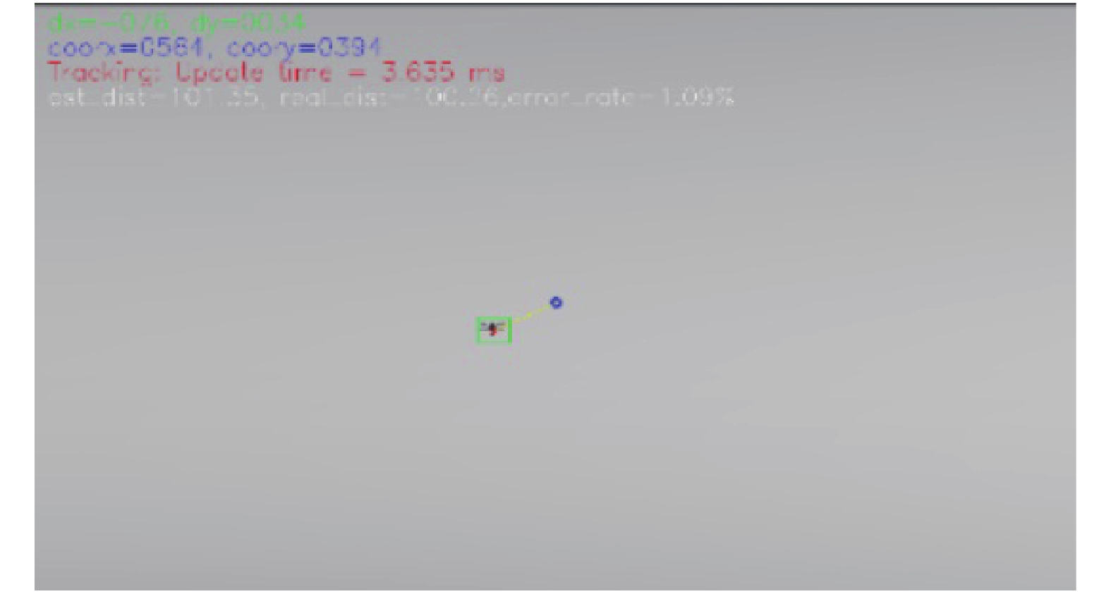
该仿真平台由三维物理场景构建系统、图像处理系统以及轨迹构建实时计算系统构成。其中,三维物理场景系统利用Gazebo提供的物理引擎搭建而成,具有包括重力场、风力场以及地磁场在内的各种物理环境变量[14],可以模拟在海陆空多种场景下物体的运动状态,有较高的拟真度;图像处理系统中,通过编写虚拟红外图像生成插件,结合赋予对应物体的温度特性,可以生成图3所示的虚拟的红外热成像图像,并通过滤波以及阈值化等处理手段,将红外图像转化为可供OpenCV处理的灰度图像,利用OpenCV计算机视觉库以及KCF算法进行图4所示的实时性较高的目标识别与跟踪[15],将目标中心坐标等识别跟踪结果输出,通过图5所示的数据流进行数据分发与传输;轨迹实时构建系统中,测量机结合三维场景构建系统中自身导航定位系统解算出来的位置与姿态信息、红外吊舱相对于机身的位置姿态信息以及图像处理系统提供的目标点中心坐标序列数据,执行轨迹重构,并实时输出重构结果。最后,通过图6所示的结果展示窗口综合展示目标识别追踪与轨迹重构的相关结果。

图 4 可见光、材质特征标识与模拟红外成像示例图
Figure 4. Visible light, material identification and simulated infrared imaging example diagram

图 5 红外目标动态识别追踪仿真图
Figure 5. Infrared target dynamic recognition and tracking simulation diagram

图 3 动态仿真平台数据流示意图
Figure 3. Data flow diagram of dynamic simulation platform

图 6 动态仿真平台实时运行数据显示窗口
Figure 6. Real-time data display window of dynamic simulation platform
如图7所示,基于PX4飞行平台软件在环仿真的两台无人机按照预设的轨迹与运动参数进行实时自主导航与飞行。为了降低定位测姿误差对轨迹重构算法的影响,无人机平台搭载了厘米级差分定位系统与高性能惯性导航器件,可以实现厘米的导航精度与分米级的控制精度。

图 7 无人机任务规划与飞行轨迹示意图
Figure 7. Schematic diagram of UAV mission planning and flight trajectory
-
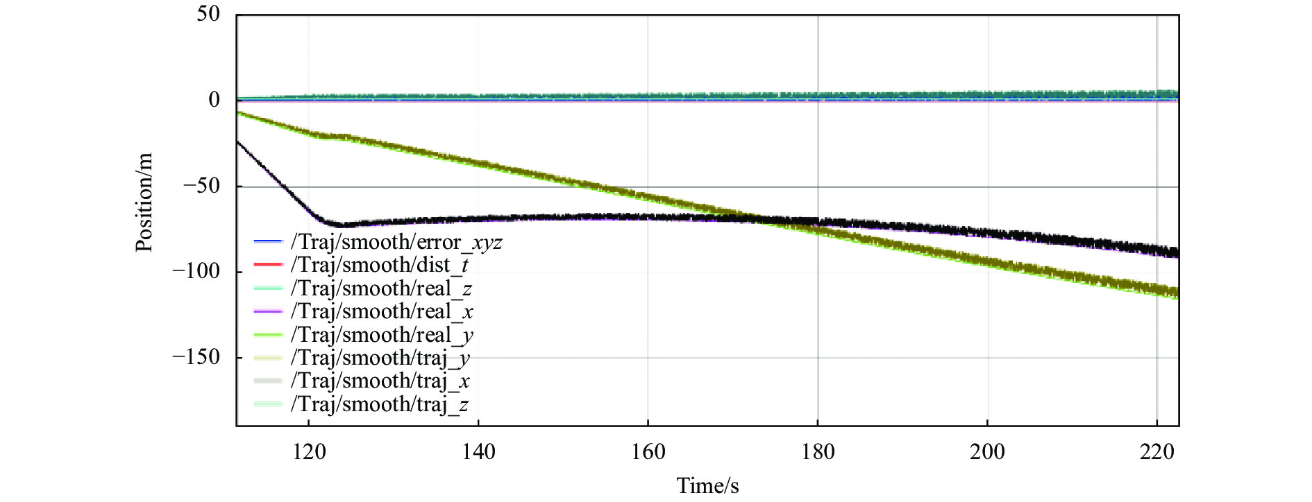
构建动态仿真平台的最终目的是验证轨迹重建算法的效果,其中最重要的评价指标之一为轨迹重建的相对误差。为了实现对算法性能的充分评估,按照不同的运动模型进行了大量的仿真,获得了一批重建结果,如图8所示。
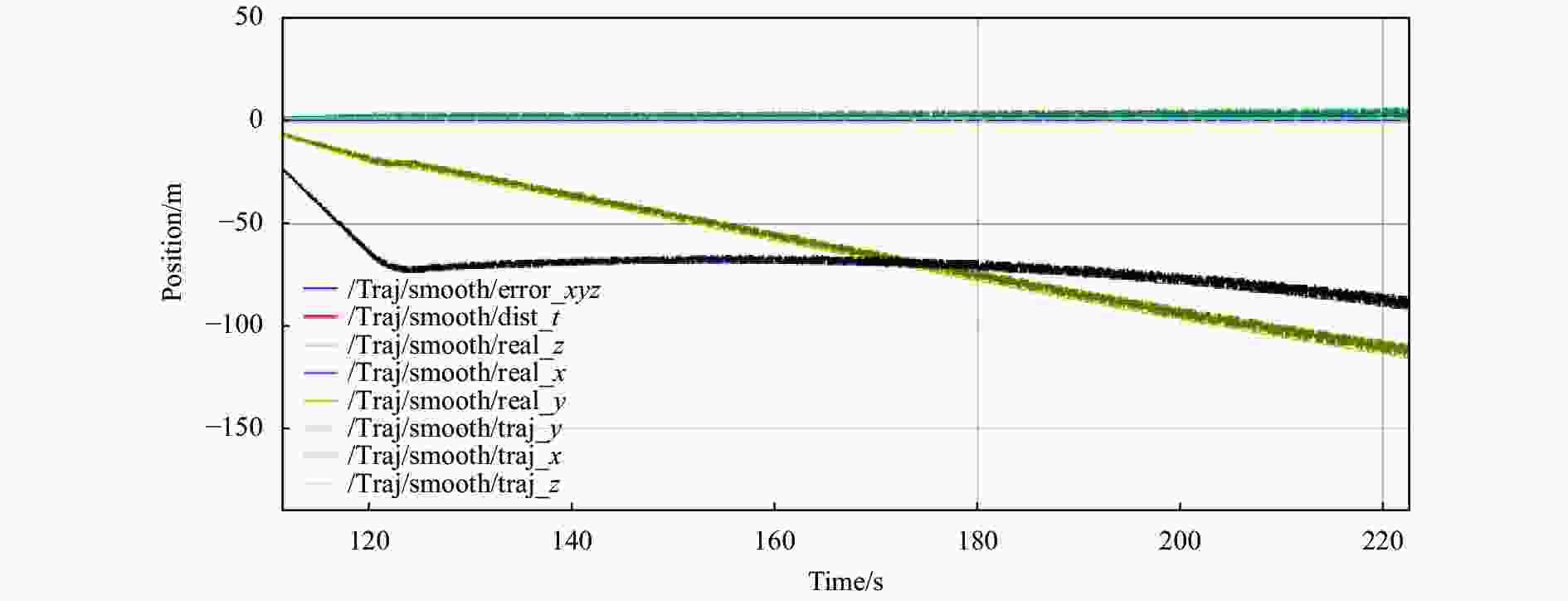
图 8 运动目标动态轨迹重建结果图
Figure 8. Results of dynamic trajectory reconstruction for moving target
为了定量评估轨迹重构算法的精度,将运动目标三维轨迹重建相对误差率定义为:
$$ {\varepsilon }_{r}=\frac{\displaystyle\sum \nolimits_{i=1}^{N}\frac{1}{N}{\left\|\widehat{{{X}}_{\mathit{i}}}-{{X}}_{\mathit{i}}\right\|}_{2}}{{\left\|{{X}}_{\mathit{i}}\right\|}_{2}} $$ (15) 式中:$\widehat{{X}}$为重建得到的运动目标三维轨迹;${X}$为Gazebo中提供的目标运动的实际三维轨迹;${N}$为数据点的总个数。
选取三种典型的运动模型代入仿真系统中,得到的误差分析结果如表2所示。
表 2 不同运动模型下轨迹重建平均误差
Table 2. Average error of trajectory reconstruction under different motion models
Target motion model Camera motion model Reconstruction errors Uniform linear motion (@5 m/s) Accelerated motion (@0.05 g) 0.89% Uniform accelerated motion (@0.05 g) Circular motion 1.09% Circular motion 3rd motion 1.45% 由表2可知,基于平滑约束的三维轨迹重构算法对不同的目标运动模型均具有较高的适用性与解算精度,可以比较准确地还原红外目标的实际运动轨迹,具备一定的实用性。
-
通常,对Gazebo平台的仿真性能评估是基于RTF值的极值与均值进行的。RTF为表征模拟运行速率与真实运行速率比值的一个参数,在不考虑与真实时钟同步的情况下可以通过提高RTF期望值来加大仿真负载,继而得到仿真系统的最大仿真能力。由于文中的动态仿真平台同时运行了PX4的软件在环仿真,其对于时钟的准确度与稳定性要求较高,故为了保证软件在环仿真的稳定运行,采用平均资源占用率来衡量平台的运行效能、稳定性与实时性。
所用的计算平台核心配置如表3所示。在双机动态轨迹重构全速运行的场景下,Gazebo仿真界面的帧率稳定为62.5 fps,图像序列长度设置为${F}=300$,实时资源占用率曲线如图9所示。
表 3 实验平台参数
Table 3. Experimental platform parameters
OS CPU GPU Ubuntu 18.04 LTS Ryzen R7-3700 X RTX2070 SUPER 
图 9 系统资源占用率曲线
Figure 9. System resource occupancy curve
可见,该仿真平台高负荷运行时的资源占用率小于40%,且RTF稳定为1,表明整套系统具有较高的运行效能与实时性。
-
文中提出了一种红外运动目标轨迹重构动态仿真的方法。通过温度特性数值计算模拟生成红外热成像视频,对热成像视频进行滤波以及阈值化处理,得到方便计算机视觉处理的灰度图像,利用KCF算法进行实时目标识别与追踪,采用平滑约束法实现目标轨迹的实时三维重构。与固定数据集作为数据源的仿真方法相比,文中的真实物理引擎及SITL软件在环动态仿真方法极大地提升了仿真的灵活性与可信度,可以在不同运动模型和场景下检验轨迹重构算法的性能。实验结果表明:文中构建的动态仿真平台具有较高的效能与通用性,可为后续的轨迹重构算法优化提供较为理想的训练与测试环境,提高算法开发效率。
Dynamic simulation platform of infrared moving target trajectory reconstruction
-
摘要: 提出了一种红外热成像视频中运动目标识别追踪以及轨迹重构的动态仿真方法。通过仿真环境中虚拟红外图像的生成方式与成像的基本模型,对得到的图像进行一系列预处理。以空对空场景搭建了基于Gazebo与OpenCV的动态仿真平台,利用平滑约束算法对追踪目标进行实时动态轨迹重构,提出了误差分析模型,并分析出轨迹重构算法的性能以及仿真平台的效能。实验结果表明,该方法针对空对空场景下的红外运动目标轨迹重构具有较好的精度与鲁棒性,对目标的运动模型基本没有约束,同时仿真平台具有较高的运行效能与实时性,普通家用电脑即可实现高于60 fps的实时动态仿真,满足轨迹重构算法性能测试与训练的需求,其核心算法亦可迁移至机载计算平台实现真实场景下的实时轨迹重构。所提出的单路热成像视频中运动目标轨迹重构动态仿真方法对空间目标三维轨迹重建与动态测距定位的研究具有重要意义。Abstract: A dynamic simulation method for moving target recognition tracking and trajectory reconstruction in infrared thermal imaging video was proposed. Through the generation of virtual infrared images in the simulation environment and the basic model of imaging, a series of preprocessing was performed on the obtained images. A dynamic simulation platform based on Gazebo and OpenCV was built in the air-to-air scene. The smooth constraint algorithm was used to reconstruct the real-time dynamic trajectory of the tracking target. The error analysis model was proposed, and the performance of the trajectory reconstruction algorithm and the effectiveness of the simulation platform were analyzed. The experimental results show that this method has good accuracy and robustness for the trajectory reconstruction of infrared moving target in air-to-air scenario, and basically has no constraint on the motion model of the target. At the same time, the simulation platform has high operation efficiency and real-time performance. The real-time dynamic simulation above 60 fps can be realized by the ordinary household computer, which meets the performance test and training requirements of the trajectory reconstruction algorithm. The core algorithm can also be migrated to the airborne computing platform to realize the real-time trajectory reconstruction in the real scene. The proposed dynamic simulation method of moving target trajectory reconstruction in single-channel thermal imaging video is of great significance to the research of three-dimensional trajectory reconstruction and dynamic ranging and positioning of space targets.
-
Key words:
- dynamic simulation /
- infrared imaging /
- trajectory reconstruction /
- smoothing constraint
-
图 4 可见光、材质特征标识与模拟红外成像示例图
Figure 4. Visible light, material identification and simulated infrared imaging example diagram
图 5 红外目标动态识别追踪仿真图
Figure 5. Infrared target dynamic recognition and tracking simulation diagram
图 6 动态仿真平台实时运行数据显示窗口
Figure 6. Real-time data display window of dynamic simulation platform
图 7 无人机任务规划与飞行轨迹示意图
Figure 7. Schematic diagram of UAV mission planning and flight trajectory
图 8 运动目标动态轨迹重建结果图
Figure 8. Results of dynamic trajectory reconstruction for moving target
表 1 红外热像仪的相关参数
Table 1. Related parameters of infrared thermal imager
Parameter Value Focal length 13 mm Sensitivity <40 mk@30 ℃ FOV 45°(H)×37°(W) Resolution 640×512 pixel Pixel pitch 17 μm Frame rate 30 Hz  下载: 导出CSV
表 2 不同运动模型下轨迹重建平均误差
Table 2. Average error of trajectory reconstruction under different motion models
Target motion model Camera motion model Reconstruction errors Uniform linear motion (@5 m/s) Accelerated motion (@0.05 g) 0.89% Uniform accelerated motion (@0.05 g) Circular motion 1.09% Circular motion 3rd motion 1.45%
下载: 导出CSV
表 3 实验平台参数
Table 3. Experimental platform parameters
OS CPU GPU Ubuntu 18.04 LTS Ryzen R7-3700 X RTX2070 SUPER
下载: 导出CSV
-
[1] Peng Chen, Chen Qian, Qian Weixian, et al. Infrared moving targets tracking under complex ground scene [J]. Infrared and Laser Engineering, 2013, 42(6): 1410-1414. (in Chinese) [2] Sun Zhaolei, Hui Bin, Qin Mofan, et al. Object detection method based on saliency measure for infrared radiation image [J]. Infrared and Laser Engineering, 2015, 44(9): 2633-2637. (in Chinese) [3] Wang Ying, Huang Jianming, Wei Xiangquan. Infrared imaging simulation of space target in orbit [J]. Infrared and Laser Engineering, 2015, 44(9): 2593-2597. (in Chinese) [4] Liu Lianwei, Dong Shikui, Chen Qianrong, et al. Infrared radiation imaging calculation of aerial target based on CUDA parallel computing [J]. Infrared and Laser Engineering, 2020, 49(4): 0404003. (in Chinese) doi: 10.3788/IRLA202049.0404003 [5] Li Zhihua, Li Xinguo. Infrared small moving target detection and tracking based on OpenCV [J]. Infrared and Laser Engineering, 2013, 42(9): 2561-2565. (in Chinese) [6] Zhao Fei, Lu Huanzhang. Infrared dim small target trajectory detection algorithm based on short-term trajectory detection [J]. Electronics, 2014, 42(1): 175-181. [7] Li Bo, Zhao Huaici, Hua Haiyang. Infrared multispectral image simulation method [J]. Infrared and Laser Engineering, 2014, 43(6): 1972-1976. (in Chinese) [8] Liu Changjian, Zhang Yi. 3D trajectory reconstruction from monocular vision based on prior spatial knowledge [J]. IEEE Sensors Journal, 2016, 16(3): 817-822. doi: 10.1109/JSEN.2015.2487039 [9] Zhou Jian, Shang Yang, Zhang Xiaohu, et al. A trajectory and orientation reconstruction method for moving objects based on a moving monocular camera [J]. Sensors, 2015, 15(3): 5666. doi: 10.3390/s150305666 [10] Zhao Gongmei, Gu Xianyu. Motion trajectory reconstruction method based on infrared sensors [J]. Laser Journal, 2021, 42(9): 155-160. [11] Lu Xituan, Lv Hui, Tian Xuetao, et al. Design of UAV infrared reconnaissance target and visible image fusion [J]. Electro-Optics and Control, 2020, 27(5): 74-79. [12] Dai Yuchao, He Mingyi, Li Hongdong, et al. Smooth constraint method for 3D reconstruction of moving target trajectory in monocular video [J]. Chinese Science, 2012, 42(8): 988-1006. (in Chinese) [13] Li Yansheng, Zhang Yongjun, Yu Jingang, et al. A novel spatio-temporal saliency approach for robust dim moving target detection from airborne infrared image sequences [J]. Information Sciences, 2016, 369: 548-563. [14] Xiao K, Tan S, Wang G, et al. XTDrone: A customizable multi-rotor UAVs simulation platform [C]//4th International Conference on Robotics and Automation Sciences (ICRAS), 2020: 55-61. [15] Lu Xiaojie, Han Guicheng, Yao Bo, et al. Research on calibration technology of binocular ranging system for thermal infrared camera [J]. Laser & Infrared, 2020, 50(5): 567-572. (in Chinese) -

 点击查看大图

计量
- 文章访问数: 304
- HTML全文浏览量: 173
- PDF下载量: 89
- 被引次数: 0

