


-
激光雷达是一种利用激光主动成像的传感器,具有高探测精度、低光照影响、易获取高精度三维信息、远有效探测距离等优点,近年来得到广泛的应用,尤其在自动驾驶领域,是自动驾驶车辆的周围三维环境感知设备。
当前对激光雷达运动目标的检测和识别主要有两类方法,一类是基于场景变化的检测,一类是基于当前图形的检测和识别。当前基于场景的变化检测主要应用二维视频图像中动目标的检测方法,典型的方法包括帧差分法、背景减除法以及光流法[1]。帧差分法原理为对若干相邻帧进行差分运算,特点是计算量小,实时性最高,缺点是存在空洞现象,易受噪声的影响,对复杂场景的适应性比较差[2];背景减除法通过对背景建模后再通过求差得到前景,从而完成动目标检测,典型方法包括单高斯模型法、高斯混合模型法、视觉背景提取(Visual Background Extractor,ViBe)算法。单高斯模型法利用背景像素值服从高斯分布对背景建模,具有运算速度快的优点,但背景适应性差,易出现鬼影、拖影等现象[3];高斯混合模型法利用多个高斯模型表示各个像素点,能够适应复杂但变化缓慢的背景,如树木的晃动、平台的振动[4]。ViBe算法采用邻域像素背景建模及随机替换背景像素的方法,具有计算量小、检测效果好等优点,但存在鬼影、检测不完整和背景适应性不足等问题[5],易出现错检和漏检,当然当前也提出了很多改进的方法[6]。光流法通过计算每一个像素的运动场并分析其变化,然后从背景中分离运动目标,由于计算量比较大,一般设备实时性不能保证,所以应用较少[7]。基于场景变化的检测方法适用于背景变化不剧烈的监视场合。基于当前图形检测和识别的方法是在单帧激光雷达的点云数据中进行目标检测与识别,可用于自动驾驶等背景剧烈变化的场景。当前直接从单帧点云数据实现目标检测和识别的方法分为两类:一类是基于传统的多阶段目标分割和识别方法;另一类为基于深度学习的直接目标识别方法[8]。传统多阶段目标分割和识别法分阶段完成数据预处理、地面点与背景点移除、点云聚类、目标识别。地面点和背景点滤除的典型方法包括利用随机采样一致性算法(Random Sample Consensus Algorithm,RANSAC)拟合地平面的方法[9]和基于栅格高度信息差的方法。点云聚类典型算法包括欧氏聚类算法和区域增长算法。目标识别有两种技术途径,一种是基于传统提取点云对象特征后分类或模型匹配的方法,另一种是基于深度学习的方法,网络模型有VoxelNet[10]、PointNet++[11]等。基于深度学习的直接目标识别方法采用深度学习算法直接对目标检测和识别[12],典型算法有Point-RCNN[13]、Faster RCNN[14]、Yolov3[15]、SSD[16]等。
激光雷达应用到周边监视时,区别于微波高分辨率成像雷达如ISAR等,工作在远距离模式时,目标点云比较稀疏[17]。作者利用NVIDIA Jetson TX2 8 G Developer Kit人工智能开发套件平台[18-19],采用直接深度学习的方法对合作目标进行训练和实时识别,点云数量为6000~7000/帧的三维点云数据识别速度低于12 Hz,而且对合作目标的识别率有待提高,出现一些漏警。针对上述问题,实际工程中将激光雷达和高分辨率红外相机相结合,鉴于高分辨率相机一般视场比较小,采用激光雷达对目标进行检测,并引导高分辨率红外相机对检测的目标进行高分辨率精细成像后再进行识别。文中针对激光雷达引导高分辨率相机时快速检测运动目标的方法进行了研究,给出了复杂场景利用三维高斯法和杂波图CFAR检测运动目标的处理方法。
-
激光雷达点云数据是无序的,密度不均匀,为了便于数据处理,需要构建点云数据三维栅格(Construction 3D Mesh),过程为:
令I(i,j,k)表示栅格化后的栅格点强度值,对于每个栅格(i,j,k)对应点云所在空间位置(xi,yj,zk),如果存在点云集合S,其空间位置(x,y,z)∈S,即
$$ \left|x_{\mathrm{i}}-x\right|< \Delta x / 2, \quad\left|y_{\mathrm{j}}-y\right| < \Delta y / 2, \quad\left|z_{\mathrm{k}}-z\right|< \Delta z / 2 $$ (1) 式中:Δx、Δy、Δz为点云空间距离、方位、高度三个方向划分栅格的单位长度,于是有:
$$ I(i,j,k) = \frac{1}{N}\sum\limits_{(x,y,z) \in S} {I(x,y,z)} $$ (2) 式中:N为点云空间位置满足公式(1)的点云的数量。如果不存在点云集合S,即N=0,则:
$$ I(i, j, k)=0$$ (3) 由于对部分点云求均值,所以在一定程度完成均值滤波的功能。
-
由于激光雷达电路中噪声和干扰以及环境影响,点云数据含有很多噪声,典型的为高斯噪声和椒盐噪声。噪声在目标检测中会增加虚假目标,因此需要滤除或降低噪声的影响。典型滤波方法有均值滤波、双边滤波、条件滤波、高斯滤波法等。双边滤波法将目标的强度和距离结合处理,可滤除高斯噪声平滑图像,而且能够保留边缘信息[20]。
三维双边滤波分别在空间域和强度域加权,设(i, j, k)为待求点空间坐标,(l, m, n)为邻域空间坐标,空间两点(i, j, k)、(l, m, n)的欧氏距离为:
$$ D = \sqrt {{{(i - l)}^2} + {{(j - m)}^2} + {{(k - n)}^2}} $$ (4) 三维空间的空间域加权系数为对三维高斯函数离散化得到的高斯核:
$$ {W_d}(i,j,k,l,m,n,{\delta _d}) = {{\rm e}^{ - \tfrac{{{{(i - l)}^2} + {{(j - m)}^2} + {{(k - n)}^2}}}{{2{\delta _d}^2}}}} $$ (5) 式中:δd为空间域标准差。强度域加权系数为:
$$ {W_I}(i,j,k,l,m,n,{\delta _I}) = {{\rm e}^{ - \tfrac{{|I(i,j,k) - I(l,m,n){|^2}}}{{2{\delta _I}^2}}}} $$ (6) 式中:δI为强度域标准差。总的权重系数为:
$$ \begin{split} W\left(i, j, k, l, m, n, \delta_{{d}}, \delta_{{I}}\right)=& W_{{d}}\left(i, j, k, l, m, n, \delta_{{d}}\right) \cdot\\ & W_{{I}}\left(i, j, k, l, m, n, \delta_{{I}}\right) \end{split}$$ (7) 空间点(i,j,k)的双边滤波运算式为:
$$ I_F^{}(i,j,k) = \dfrac{{\displaystyle\sum\limits_{(l,m,n) \in S} {W(i,j,k,l,m,n,{\delta _d},{\delta _I})I(l,m,n)} }}{{\displaystyle\sum\limits_{(l,m,n) \in S} {W(i,j,k,l,m,n,{\delta _d},{\delta _I})} }} $$ (8) S为以空间点(i, j, k)为中心的模板,满足|l−i|≤Nx,|j−m|≤Ny,|k−n|≤Nz。Nx、Ny、Nz为三个方向高斯核尺寸,为奇数。
-
在减小噪声的影响后,接下来将目标从背景分割出来。激光雷达引导高分辨相机时工作于监视模式,背景变化不剧烈,因此采用基于变化的检测方法。点云数据含有距离信息,直接利用三维场景的点云数据进行检测,由于叠加了距离信息,相比变换为二维图像再检测可提高检测的准确度。帧差分法对背景的适应能力不足,所以文中主要研究利用高斯模型和杂波图CFAR方法在三维空间对背景建模,并分割出运动目标。
-
三维单高斯模型法(3D Single Gaussian Model, 3D SGM)的原理为三维场景中每一点的强度值为一个随机过程,并且强度值服从高斯分布。设任意时刻t、坐标为(x, y, z)的第j个栅格点的强度值Ij,t=I(x, y, z, t),Ij,t为随机变量的采样值,其强度值的概率密度函数为:
$$ {P_j}({I_{j,t}}) = G({I_{j,t}},{u_{j,t}},{\delta _{j,t}}) = \frac{1}{{{\delta _{j,t}}\sqrt {2\pi } }}{{\rm e}^{ - \frac{{{{({I_{j,t}} - {u_{j,t}})}^2}}}{{2{\delta _{j,t}}^2}}}} $$ (9) 式中:t=1,2,···,N为离散时间,对应点云数据帧序列;uj,t和δj,t为t时刻点j强度值的期望值和方差。令Dj,t代表场景空间第j个点t时刻的检测结果,值“1”表示目标点,“0”表示该点为背景。用下式分割前景和背景:
$$ {D_{j,t}} = \left\{ {\begin{array}{*{20}{c}} 1&{|{I_{j,t}} - {u_{j,t}}| \gt \lambda {\delta _{j,t}}} \\ 0&{\rm otherwise} \end{array}} \right. $$ (10) 式中:λ为方差缩放因子,其值决定虚警率和漏警率。
第j点检测概率Pd,j和虚警概率Pf,j分别为:
$$ {P_{d,j}}(t) = \int\limits_T^\infty {\frac{1}{{{\delta _{j,t}}\sqrt {2\pi } }}{{\rm e}^{ - \tfrac{{{{(I_{j,t} - {u_{j,t}})}^2}}}{{2{\delta _{j,t}}^2}}}}{\rm{d}}I_{j,t}} $$ (11) $$ {P_{f,j}}(t) = \int\limits_T^\infty {\frac{1}{{{\delta _{j,t}}\sqrt {2\pi } }}{{\rm e}^{ - \tfrac{{{I_{j,t}^2}}}{{2{\delta _{j,t}}^2}}}}{\rm{d}}I_{j,t}} $$ (12) 式中:T为检测门限。其值为:
$$ T = {u_{j,t}} + \lambda \cdot {\delta _{j,t}} $$ (13) 对场景背景模型进行每帧更新,常见的更新的算法如公式(14)、(15)所示:
$$ u_{j, t}=\alpha u_{j, t-1}+(1-\alpha) I_{j, t} $$ (14) $$ \delta_{j, t}=\alpha \delta_{j, t-1}+(1-\alpha)\left|I_{j, t}-u_{j, t}\right|$$ (15) 式中:α为背景更新速率,值越大背景更新越慢,越能适应运动速度比较慢的目标检测,但也会因背景缓慢变化而导致虚警率上升。
-
对于复杂场景,如树木晃动或雷达振动等因素会使三维空间单高斯法产生较高虚警,改进方法为三维空间高斯混合法(3D Gaussian Mixture Model, 3D GMM)[4]。三维高斯混合法对空间每个背景点的强度值用K个高斯分布叠加来表示,根据实时性的要求选择K,一般K取3~5,K越大,应对复杂场景的能力越强,当K=1时,为三维单高斯模型。同样对三维场景第j个背景点,其强度值概率密度函数为:
$$ P({I_{j,t}}) = \sum\limits_{i = 1}^K {{W_{j,i,t}}} G({I_{j,t}},{u_{j,i,t}},{\delta _{j,i,t}}) $$ (16) 式中:Wj,i,t为t时刻第j个点第i个高斯模型的权值;uj,i,t和δj,i,t为t时刻点j强度值的第i个高斯分布的期望值和方差,并且
$$ \sum\limits_{i = 1}^K {{W_{j,i,t}}} = 1 $$ (17) G(Ij,t,uj,i,t,δj,i,t)为t时刻第i个高斯分布函数,定义为:
$$ G({I_{j,t}},{u_{j,i,t}},{\delta _{j,i,t}}) = \frac{1}{{{\delta _{j,i,t}}\sqrt {2\pi } }}{{\rm e}^{ - \frac{{{{({I_{j,t}} - {u_{j,i,t}})}^2}}}{{2{\delta _{j,i,t}}^2}}}} $$ (18) 如果存在样本数据,K个高斯分布的参数Wj,i,t、uj,i,t和δj,i,t可通过期望最大化算法(Expectation-Ma-ximization,EM)[21]求解;否则通过第一帧初始化参数和接下来的帧实时更新K个高斯分布参数,同时完成目标检测。在每个时刻t,根据Wj,i,t/δj,i,t从大到小通过公式(19)判决是背景点还是目标点。
$$ {D_{j,t}} = \left\{ {\begin{array}{*{20}{c}} 1&{|{I_{j,t}} - {u_{j,i,t}}| \gt \lambda {\delta _{j,i,t}},i = 1,\cdots,K} \\ 0&{\rm otherwise} \end{array}} \right. $$ (19) 三维高斯混合模型法在更新每帧参数时,需要更新每个栅格对应的 参数Wj,i,t、uj,i,t和δj,i,t,其中uj,i,t和δj,i,t的更新算法参照公式(14)、(15)。在判定为背景点时,设此时i=P,则栅格j的权值的更新策略为:
$$ {W_{j,i,t}} = \left\{ {\begin{array}{*{20}{l}} {(1 - \alpha ){W_{j,i,t - 1}} + \alpha }&{i = P} \\ {(1 - \alpha ){W_{j,i,t - 1}}}&{{\text{otherwise}}} \end{array}} \right. $$ (20) 对判定为目标的栅格点j的权值更新策略为:
$$ {W_{j,i,t}} = \left\{ {\begin{array}{*{20}{l}} {(1 - \alpha ){W_{j,i,t - 1}} + \alpha }&{i = K} \\ {(1 - \alpha ){W_{j,i,t - 1}}}&{i \ne K} \end{array}} \right. $$ (21) 实现时需要根据Wj,i,t/δj,i,t对高斯模型进行排序,计算量会增大若干倍,导致检测的实时性降低。
-
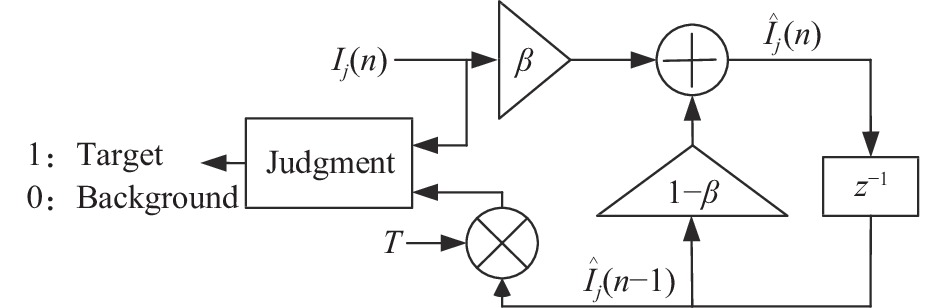
三维高斯法适用于背景变化平稳、强度为高斯分布的场景,对非平稳、非高斯分布(如瑞利分布、对数正态分布、韦布尔分布、K分布等)的具有低虚警率和高实时性的方法是杂波图CFAR (Clutter Map Constant False Alarm Rate,Clutter map CFAR)处理方法[22]。该方法在保持虚警率恒定的情况下对接收的含目标和杂波与噪声信号进行处理,从而判别是否存在目标。检测时,每个栅格看成一个检测单元,并且各栅格的激光回波强度非相参相互独立,原理如图1所示,通过一阶递归数字滤波器迭代确定检测门限,其中β为遗忘因子,0≤β≤1,如果检测目标为慢速运动目标,β取较小值,对快速运动目标,β取较大值,但会使场景平稳性变差;T为检测门限因子,此因子决定了检测概率和虚警率;n为帧次,z−1表示取上一帧,即n−1帧。

图 1 杂波图CFAR检测的原理
Figure 1. Principle of clutter-map CFAR detection
对三维场景第j个栅格,第n帧强度值为Ij(n),背景估计值为
$ {\hat I_j}(n) $ ,由图1可得:$$ {\hat I_j}(n) = \beta {I_j}(n) + (1 - \beta ){\hat I_j}(n - 1) $$ (22) 公式(22)自身反复迭代可得:
$$ {\hat I_j}(n) = \beta \sum\limits_{l = 0}^n {{{(1 - \beta )}^l}} {I_j}(n - l) $$ (23) 判决准则是:
$$ {D_j}(n) = \left\{ {\begin{array}{*{20}{c}} 1&{{I_j}(n) \geqslant T \cdot {{\hat I}_j}(n - 1)} \\ 0&{{I_j}(n) \lt T \cdot {{\hat I}_j}(n - 1)} \end{array}} \right. $$ (24) 式中:
$ T \cdot {\hat I_j}(n - 1) $ 为自适应检测门限。在激光雷达回波中噪声和杂波符合均匀瑞利分布[23],并且回波强度符合Swerling I模型,则反射强度为I的概率密度函数为:
$$ f(I) = \left\{ {\begin{array}{*{20}{c}} {\dfrac{1}{p}{{\rm e}^{ - \tfrac{I}{p}}}}&{{H_0}} \\ {\dfrac{1}{{p(1 + \gamma )}}{{\rm e}^{ - \tfrac{I}{{p(1 + \gamma )}}}}}&{{H_1}} \end{array}} \right. $$ (25) 式中:p为只有杂波与噪声的总强度;γ为目标强度对杂波强度的平均比值;H0为回波中无目标情况;H1为回波中存在目标的情况。
在n<n1时,Ij(n)相对Ij(n1)统计独立,则可得检测概率为:
$$ {P_d} = \prod\limits_{l = 0}^\infty {{{[1 + \frac{{T\beta {{(1 - \beta )}^l}}}{{1 + \gamma }}]}^{ - 1}}} $$ (26) 虚警概率为:
$$ {P_f} = \prod\limits_{l = 0}^\infty {{{[1 + T\beta {{(1 - \beta )}^l}]}^{ - 1}}} $$ (27) 在指定虚警率后,通过公式(27)可以得到检测门限因子T。
杂波图CFAR方法计算量比较小,效率很高,并且能够消除目标遮蔽现象,具有良好的多目标检测能力,同时还具有较好的边缘虚警控制能力;通过调节检测门限因子T可控制虚警率,通过调节遗忘因子β可以适应不同速度的运动目标,包括地面行人和车辆、空中飞行器等,因此,激光雷达采用杂波图CFAR检测目标具有良好的效果,值得进一步研究。
-
经过分割的三维图形,其目标以及噪声引起的虚假目标的值为“1”,其他均为“0”。形态学处理(Morpho-logical Processing)可实现部分虚警点的消除、连通图的标记。目标参数提取实现目标中心位置、目标尺寸的计算。这些参数传输到高分辨相机,再由该相机的平台控制系统进一步拟合和预测,得出目标的空间精确位置并转向该方位进行高分辨成像和识别。
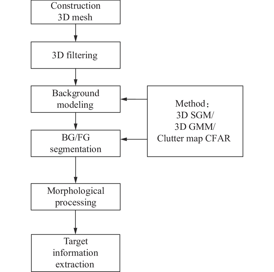
总结激光雷达点云数据目标快速检测的处理流程如图2所示。图中BG/FG为Background/Foreground的缩写。

图 2 激光雷达点云数据目标快速检测处理流程
Figure 2. Processing flow diagram of rapid target detection for lidar point cloud data
-
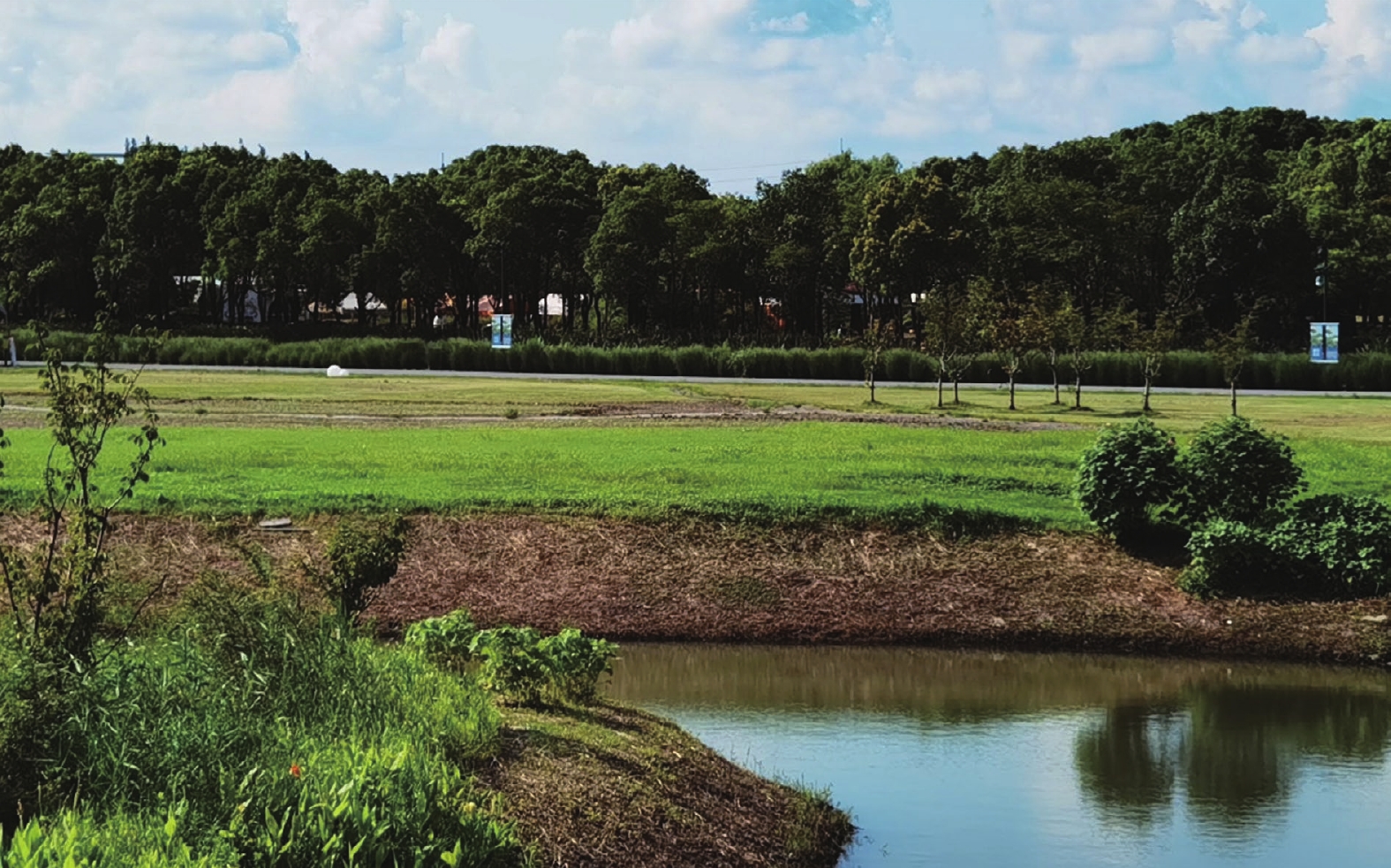
利用由中国科学院上海光学精密机械研究所量子光学重点实验室研制的激光雷达样机进行了验证,为实验方便,激光雷达作用距离设在100~160 m范围,点云数据帧频为14 Hz,合作目标为一大型客车,行驶速度10~20 km/h。仿真工具为MATLAB R2012,运算时间测算环境如表1所示。实验的外场位置位于上海嘉定郊野公园,场景如图3所示,由于主要应用场合在夜晚,所以实验在夜间进行。
表 1 运算时间测算环境
Table 1. Environment of time measurement and calculation
Platform Parameters CPU Intel Core i7-6700 OS Windows10 Development platform Visual studio 2010 Language C++ 
图 3 实验场地场景
Figure 3. Scene of the experiment
原始点云数据三维图形如图4所示。图中随着反射强度值逐渐增大,点云显示颜色从深蓝色向深红色过渡,如颜色条所示。合作目标反射较强,图中红色点云为合作目标点云,蓝色点云为反射比较弱的树木等背景点云。栅格化处理结果如图5所示,栅格大小为1 m×1 m×1 m,由于位置集中在一起的部分点云合并,所以图中点云数量从6718变为5902。点云三维滤波后的结果如图6所示,核尺寸为3,经过平滑处理后,有些栅格原来强度值为0,滤波后不为0,原来强度比较大的点强度变小,整体点云强度值减小,因此,整体图形显示颜色偏深蓝色。采用三维单高斯模型分割背景和目标结果如图7所示,采用三维高斯混合模型分割背景和目标结果如图8所示,采用杂波图CFAR方法分割背景和目标结果如图9所示。分割以后背景点云不再显示,只显示目标点云。

图 4 实际点云数据三维图形表示
Figure 4. 3D graphic of actual point cloud data

图 5 栅格化处理结果三维图形显示
Figure 5. 3D graphic of mesh processing result

图 6 三维滤波结果图
Figure 6. Diagram of 3D filtering result

图 7 三维单高斯模型法分割结果
Figure 7. Segmentation result of 3D SGM

图 8 三维高斯混合模型法分割结果
Figure 8. Segmentation result by 3D GMM

图 9 杂波图CFAR法目标检测结果
Figure 9. Target detection result by clutter-map CFAR
从图7可以看出,该帧数据采用三维单高斯模型分割结果中存在杂散点和“重影”。由图8、图9可见三维高斯混合模型和杂波图CFAR分割后已经不存在杂散点和“重影”了,并且轮廓相对完整。
将分割的目标各点投影到方位平面(Y-Z平面)上,形成二维平面图像,如图10(a)所示。在二维距离平面上对图像进行膨胀、腐蚀形成连通图,然后通过标记连通图和计算连通图尺寸得到目标的数量和目标的尺寸(方位向)以及中心位置坐标,如图10(b)所示。

图 10 三维处理结果在方位平面的投影
Figure 10. Projection of 3D processing results in azimuth plane
对实际含有合作目标的72帧点云数据采用不同方法进行了处理,采用pytorch的深度学习模型FasterRCNN Resnet50 FPN,在普通计算机(CPU:Intel酷睿i5 6200 U,2.3 GHz主频,集成显卡)单帧投影的2D灰度图像数据(152×60)处理时间为8.6229 s,在NVIDIA Jetson TX2 8 G Developer Kit平台的单帧处理时间为0.5 s,点云数据为2 s。远距离下,利用已有的模型无法识别合作目标,通过自建数据集对合作目标识别的平均正确率为0.3184,平均召回率为0.3294。表2给出了其他检测方法的参数值及在漏警数量为0的临界条件下的虚警数量和测算的每帧处理时间。从表可以看出,二维单高斯模型下,实时性很高,但存在较多虚警,而且几乎每帧均有虚警产生;三维单高斯模型某些帧存在虚警;采用三维高斯混合模型处理,通过调整参数可以使漏警数量为0时虚警数量也降到0。采用杂波图CFAR方法后,虚警率也会大幅下降,虽存在虚警,但主要原因是某些帧里目标分离为两个部分,其中一部分判定为虚警。同时可以看到杂波图CFAR方法处理时间与三维单高斯模型法基本相等,比三维混合模型法时间少很多,能够满足实际工程需要。三维混合模型需要进一步优化或采用并行处理来提高实时性。
表 2 四种目标检测方法比较
Table 2. Comparison of four target detection methods
Method Parameters False objects False frames Time/ms 2D SGM δ=3.0,λ=1.0 282 60 5.14 3D SGM δ=3.0,λ=7.66 20 12 56.52 3D GMM δ=3.0, λ=12.66, K=5 0 0 902.45 Clutter-map CFAR β=0.005, T=4.8 3 3 58.67 -
当前对工作在远距离监视模式的激光雷达直接采用深度学习的方法检测和识别运动目标时,实时性和检测率都不完全满足实际工程要求。工程上将激光雷达和高分辨率红外相机结合,需要由激光雷达检测运动目标并引导红外高分辨率相机成像和识别。激光雷达在采用基于变化检测的方法时,将点云数据变换为二维图像再进行目标检测,实时性最高,但有很高的虚警率,直接对点云数据采用三维高斯模型进行运动目标检测,三维单高斯模型实时性比较高,并在很大程度提高了检测的准确度,降低了虚警率,但仍然偏高。采用三维高斯混合模型以适应复杂背景,进一步降低了虚警,但由于背景参数更新带来运算量的增加,降低了实时性。同样对复杂背景的场景,利用杂波图CFAR检测处理点云数据的方法,在提高检测准确率同时提高了检测的实时性,从而满足了实际工程的要求。
Fast detection of moving targets in long range surveillance LiDAR
-
摘要: 激光雷达具有全天候工作、探测精度高、有效探测距离远、易获得三维信息等特点,但工作在远距离模式时,目标点云比较稀疏。当前便携条件下,基于深度学习的算法在激光雷达点云数据直接目标识别时,实时性和成功率尚不能达到远程监视实际工程的要求。针对实际工程中利用激光雷达检测运动目标进而实时引导高分辨率相机的需求,采用基于变化的检测方法,对远距离条件下激光雷达的运动目标检测方法进行了研究,利用点云数据的距离信息,给出三维单高斯模型和三维高斯混合模型检测动目标的过程和方法,提出了利用杂波图恒虚警率检测法处理点云数据的方法。实验表明,与二维图像动目标检测方法相比,三维单高斯模型法会很大程度提高检测准确性,降低虚警率,但仍然存在较高虚警率。为适应复杂三维场景,采用基于三维高斯混合模型的方法进一步降低了虚警率,但也降低了检测速度;而杂波图CFAR的方法具有很高的实时性,同时也具有较好的检测性能。Abstract:
Objective Lidar is a kind of sensor using laser active imaging, with the advantages of high detection accuracy, all-weather working, easy access to high-precision three-dimensional information, far effective detection range, etc. It has been widely used in recent years, especially in the field of autonomous driving, as a three-dimensional environment perception device in the autonomous driving vehicles. When lidar is applied to perimeter surveillance and working in long-range mode, the target point cloud is relatively sparse which is different from microwave high-resolution imaging radar such as ISAR. The recognition speed of 3D point cloud data with the number of point clouds of 6 000-7 000/frame is lower than 12 frame/s when using training and real-time recognition of cooperative targets by deep learning method, while more missed alarms emerge. The rate of targets recognition needs to be improved. In order to guide the high-resolution infrared camera to carry out high-resolution fine imaging of the detected target before recognition, the method of fast detection of moving targets is investigated. The processing method of complex scenes using 3D Gaussian method and clutter map CFAR to detect moving targets is provided. Methods The flow diagram of lidar moving target detection based on 3D point cloud data is given (Fig.2), including 3D point cloud mesh construction, noise filtering by 3D bilateral filtering, target and background segmentation. The principles of 3D single Gaussian method and 3D Gaussian mixture method for segmentation of target/background are given, and the method of using clutter map CFAR detection is proposed (Fig.1). Using 72 frames of data from actual equipment, the result of application of the Faster RCNN Resnet50 FPN deep-learning method, two-dimensional single Gaussian method, three-dimensional single Gaussian method, three-dimensional Gaussian mixture method, and clutter map CFAR method are compared. Results and Discussions Comparative experiments show that the average accuracy rate of using the Faster RCNN Resnet50 FPN deep learning model is 0.318 4, the average recall rate is 0.329 4, the processing time of a single frame is 0.5 s, and the point cloud data is 2 s, which means this method is hardware-intensive and difficult to meet the general engineering requirements. In other methods (Tab.2), under the two-dimensional single-Gaussian model, the real-time performance is very high, but there are many false alarms, and almost every frame has false alarms. There are false alarms in some frames of 3D single Gaussian model (Fig.7). By adjusting the parameters of the 3D Gaussian mixture model, the number of false alarms can be reduced to 0 while there are no missed alarms (Fig.8). The false alarm rate will also decrease significantly after using the clutter map CFAR method (Fig.9). At the same time, it can be seen that the processing time of the clutter map CFAR method is basically the same as that of the 3D single Gaussian model method, which is much less than that of the 3D mixed model method, and can meet the actual engineering needs. The 3D Gaussian mixture model needs further optimization or parallel processing to improve real-time performance. Conclusions At present, when the deep learning method is directly used to detect and recognize moving targets for the lidar working in the remote monitoring mode, the real-time performance and detection rate can not fully meet the actual engineering requirements. The combination of lidar and high-resolution infrared camera in the project requires lidar to detect moving targets and guide the imaging and recognition of infrared high-resolution camera. Due to the high false alarm rate of two-dimensional single Gaussian method and three-dimensional single Gaussian method, it is difficult to adapt to complex background and cannot meet the requirements. Three-dimensional Gaussian mixture model can adapt to complex background very well, but the real-time performance is reduced because of the increase in the amount of computation caused by the update of background parameters. This means that it can not meet the requirements. In contrast, for the scene with complex background, the method of using clutter map CFAR to detect and process point cloud data can improve the accuracy and the real-time performance of detection, thus meeting the requirements of practical engineering. -
Key words:
- moving target detection /
- clutter map CFAR /
- lidar /
- 3D Gaussian mixture model
-
图 2 激光雷达点云数据目标快速检测处理流程
Figure 2. Processing flow diagram of rapid target detection for lidar point cloud data
表 1 运算时间测算环境
Table 1. Environment of time measurement and calculation
Platform Parameters CPU Intel Core i7-6700 OS Windows10 Development platform Visual studio 2010 Language C++  下载: 导出CSV
表 2 四种目标检测方法比较
Table 2. Comparison of four target detection methods
Method Parameters False objects False frames Time/ms 2D SGM δ=3.0,λ=1.0 282 60 5.14 3D SGM δ=3.0,λ=7.66 20 12 56.52 3D GMM δ=3.0, λ=12.66, K=5 0 0 902.45 Clutter-map CFAR β=0.005, T=4.8 3 3 58.67
下载: 导出CSV
-
[1] Deng Hao, Zheng Wei, Li Mingtao, et al. Dim moving target detection based on fluctuation analysis [J]. Optics and Precision Engineering, 2020, 28(11): 2517-2526. (in Chinese) doi: 10.37188/OPE.20202811.2517 [2] Yang Dezhen, Yu Songlin, Feng Jinjun, et al. Low false alarm infrared target detection in airborne complex scenes [J]. Optics and Precision Engineering, 2022, 30(1): 96-107. (in Chinese) doi: 10.37188/OPE.20223001.0096 [3] Song Shanshan, Zhai Xuping. Improved infrared anomaly target detection algorithm based on single Gaussian model [J]. Infrared Technology, 2021, 43(9): 885-888, 894. (in Chinese) [4] Zhen Rong, Shi Ziqiang. Ship trajectory clustering method based on Gaussian mixture model [J]. Ship Engineering, 2021, 43(11): 139-143. (in Chinese) doi: 10.13788/j.cnki.cbgc.2021.11.24 [5] Tang Min’an, Wang Chenyu. Moving object detection in static scene base on improved vibe algorithm [J]. Laser & Opto-electronics Progress, 2021, 58(14): 1410011. (in Chinese) doi: 10.3788/LOP202158.1410011 [6] Liu L, Chai G H, Qu Z. Moving target detection based on improved ghost suppression and adaptive visual background extraction [J]. Journal of Central South University, 2021, 28(3): 747-759. doi: 10.1007/s11771-021-4642-9 [7] Sun Peng, Yu Yue, Chen Jiaxin, et al. Highly dynamic aerial polymorphic target detection method based on deep spatial-temporal feature fusion (Invited) [J]. Infrared and Laser Engineering, 2022, 51(4): 20220167. (in Chinese) doi: 10.3788/IRLA20220167 [8] 杨浩哲. 面向自动驾驶的激光雷达点云实时目标聚类与识别方法研究[D]. 合肥: 中国科学技术大学, 2021. Yang H Z. Research on real time target clustering and recognition of LiDAR point cloud for autonomous driving[D]. Hefei: University of Science and Technology of China, 2021. (in Chinese) [9] Yuan H N, Sun W, Xiang T Y. Line laser point cloud segmentation based on the combination of RANSAC and region growing[C]//Proceedings of the 39th Chinese Control Con-ference, 2020: 6324-6328. [10] Maturana D, Scherer S. VoxNet: A 3D Convolutional Neural Network for real-time object recognition[C]//International Conference on Intelligent Robots and Systems(IROS). IEEE, 2015: 922-928. [11] Qi C R, Yi L, Su H, et al. Pointnet++: Deep hierarchical feature learning on point sets in a metric space[C]//Advances in Neural Information Processing Systems, 2017: 5099-5108. [12] Zhang Ruiyan, Jiang Xiujie, An Junshe, et al. Design of global-contextual detection model for optical remote sensing targets [J]. Chinese Optics, 2020, 13(6): 1302-1313. (in Chinese) doi: 10.37188/CO.2020-0057 [13] Shi S H, Wang X G , Li H S. PointRCNN: 3D object proposal generation and detection from point cloud[C]//Proceedings of the IEEE Conference on Computer Vision and Pattern Recognition (CVPR), Long Beach: IEEE, 2019: 770-779. [14] Ren S Q, He K M, Girshick R, et al. Faster R-CNN: towards real-time object detection with region proposal networks [J]. IEEE Transactions on Pattern Analysis and Machine Intelligence, 2017, 39(6): 1137-1149. doi: 10.1109/TPAMI.2016.2577031 [15] Redmon J, Farhadi A. YOLOv3: An Incremental Improvement[EB/OL]. (2018-04-08)[2022−10−09]. https://arxiv.org/abs/1804.02767. [16] Liu W, Anguelov D, Erhan D, et al. SSD: single shot multibox detector[C]//European Conference on Computer Vision (ECCV). Amsterdam, The Netherlands: Springer, 2016: 21-37. [17] Bi Yong, Pan Mingqi, Zhang Shuo, et al. Overview of 3D point cloud super-resolution technology [J]. Chinese Optics, 2022, 15(2): 210-223. (in Chinese) doi: 10.37188/CO.2021-0176 [18] Geiger A, Lenz P, Urtasun R. Are we ready for autonomous driving? The KITTI Vision benchmark suite[C]//IEEE Conference on Computer Vision & Pattern Recognition (CVPR), Providence, RI, USA. New York: IEEE, 2012: 3354-3361. [19] Geiger A, Lenz P, Stiller C, et al. Vision meets robotics: The KITTI Dataset [J]. International Journal of Robotics Research, 2013, 32(11): 1231-1237. doi: 10.1177/0278364913491297 [20] Shi Ye, Wang Xiaokai, Liu Huifeng. Research on bilateral filtering algorithm base on local filtering template [J]. Journal of Test and Measurement Technology, 2021, 35(1): 49-53. (in Chinese) doi: 10.3969/j.issn.1671-7449.2021.01.009 [21] Xing Chengbin, Gong Shengsheng, Yu Xiaoliang, et al. Application of Gaussian mixture clustering to moving surface fitting filter classification [J]. Infrared and Laser Engineering, 2021, 50(1): 20200501. (in Chinese) doi: 10.3788/IRLA20200501 [22] Nitzberg R. Clutter map CFAR analysisl [J]. IEEE Transactions on Aerospace and Electronic Systems, 1986, 22(4): 419-421. doi: 10.1109/TAES.1986.310777 [23] Ban Chao, Pan Weilin, Wang Rui, et al. Initial results of Rayleigh scattering lidar observations at Zhongshan station, Antarctica [J]. Infrared and Laser Engineering, 2021, 50(3): 20210010. doi: 10.3788/IRLA20210010 -

 点击查看大图
图(10) / 表(2)
计量
- 文章访问数: 140
- HTML全文浏览量: 28
- PDF下载量: 41
- 被引次数: 0


