


 下载:
下载:


-
传统光学成像技术利用光的强度信息实现目标探测和识别。经过数十年的研究发展,传统的光学成像技术取得了长足的进步,相应光学成像系统的设计日趋成熟,在许多领域有广泛应用。但是传统光学成像技术仍然存在许多缺点,如:只利用强度信息,无法获取光谱、偏振、相位等其它多维物理量、成像过程中光场信息丢失、无法在恶劣环境下正常工作等。事实上,光作为一种电磁波,相位、频率和偏振等参数更能反映其本质特性,其中,光的偏振特性反映了电场矢量在空间传播时的振动方向。偏振成像技术通过分析光波被物体反射前后偏振特性的改变,如偏振度、偏振角等,可获得物体的形状、材料和粗糙度等多维信息。另外,在有散射介质存在的弱光环境中,反射光的偏振信息保持能力远大于强度信息。基于此,偏振成像在地物探测和洪涝灾害监测[1-2]、通信[3-4]、医学成像[5-6]等方面有广泛应用。
偏振信息通过搭建偏振成像系统获得,根据成像系统结构的不同,偏振成像系统主要有分时型、分振幅型、分孔径型和分焦平面型四种。根据成像的空间维度,偏振成像技术可划分为偏振二维成像和偏振三维成像。在文中,偏振二维成像指对在水下、雾霾等特殊环境中获得的原始图像结合偏振信息进行处理,得到增强后的平面图像包含强度图像无法探测到的目标,而偏振三维成像相较于偏振二维成像,能够进一步恢复目标的相对深度,实现立体成像。无论是二维成像还是三维成像均是通过分析目标反射光的偏振态求解得到目标的偏振特征参数,进一步处理以实现对目标的探测。偏振二维成像通过对由偏振特征参数得到的偏振特征图像和强度图像进行联合处理,通常利用偏振差分算法[7-8]和图像融合技术实现成像[9-10],在水下探测[11-12]和图像去雾[13-14]等领域有广泛研究。偏振三维成像则是根据偏振特征参数得到物体表面的法向量场,再利用特定的算法,如:Frankot-Chellappa [15]、松弛迭代法[16]、Shapelets积分算子[17]等算法实现对某一特定目标的三维重建。相比传统的光学三维成像技术,偏振三维成像技术能够反映目标的材质、粗糙度等纹理特征,不依赖背景照度、环境温度和对比度等因素,能够在特殊环境中实现目标的有效探测。此外,超表面偏振器件在光的偏振转换、旋光、矢量光束的产生等方面的研究为偏振成像系统的便携化、实时化提供可能。综上,偏振成像技术在成像领域具有广阔的发展前景。
文中首先介绍了偏振光成像的基本理论,接着对偏振成像系统的四种典型结构进行详细介绍和比较分析,然后分别对偏振二维成像、偏振三维成像和基于超表面偏振器件的偏振探测及成像的研究进展进行综述,最后对偏振成像技术面临的挑战和未来的发展方向进行总结和展望。
-
光的偏振可以用电矢量法、琼斯矩阵法、Poincare球和Stokes矢量法来描述。在偏振成像技术的实际应用中,最为常见的是通过获取Stokes矢量求取需要的偏振特征参数,故重点介绍偏振光的Stokes矢量表示法。
-
Stokes矢量法通过简单的数学表达形式描述光的偏振态。Stokes矢量包含四个分量,各个分量可通过测量相位或特定角度的光强得到。然而,光的频率变化约为1014 Hz,现有探测器的帧频最高为百万赫兹级,无法直接获取光的相位信息。因此,通过采集特定角度(通常选取0°、±45°、90°方向)的偏振子图像并对其强度信息处理得到Stokes矢量,表示为:
$$ S = \left[ {\begin{array}{*{20}{c}} {\begin{array}{*{20}{c}} {\begin{array}{*{20}{c}} {{S_0}} \\ {{S_1}} \end{array}} \\ {{S_2}} \end{array}} \\ {{S_3}} \end{array}} \right] = \left[ {\begin{array}{*{20}{c}} {\begin{array}{*{20}{c}} {\begin{array}{*{20}{c}} {{I_{\text{0}}} + {I_{{\text{90}}}}} \\ {{I_{\text{0}}} - {I_{{\text{90}}}}} \end{array}} \\ {{I_{{\text{45}}}} - {I_{{{ - 45}}}}} \end{array}} \\ {{I_R} - {I_L}} \end{array}} \right] $$ (1) Stokes矢量S=[S0, S1, S2, S3]T可表示任意偏振光的偏振态。其中,S0表示光场总强度,S1表示0°和90°方向线偏振光的光强差,S2表示±45°方向线偏振光的光强差,S3表示左旋与右旋圆偏振光的光强差。偏振度DoP和偏振角β是用来描述偏振光特性的重要参数,用于偏振光学成像,可根据Stokes矢量计算得到,如公式(2)所示:
$$ \begin{gathered} {\rm{ DoP}} = \frac{{\sqrt {S_1^2 + S_2^2{\text{ + }}S_3^2} }}{{{S_0}}}{\text{ }} \\ {\text{ }}\beta = \frac{1}{2}\arctan \left( {\frac{{{{{{S}}}_{\text{2}}}}}{{{{{{S}}}_{\text{1}}}}}} \right) \\ \end{gathered} $$ (2) -
非偏振光入射到目标表面后的传播模型如图1所示,入射光可以分解成垂直和平行于入射平面的分量,菲涅耳方程给出了垂直(平行)于入射平面的线偏振光的反射光振幅与入射光振幅之比[18],基于此,求得非偏振光入射到目标表面后反射光和折射光的偏振度,分别表示为公式(3)、(4),其中,n表示空气中目标表面材料的折射率。

$$ {\rm{DoP}}{_r} = \frac{{\sqrt {{{\sin }^4}\theta {{\cos }^2}\theta \left( {{n^2} - {{\sin }^2}\theta } \right)} }}{{\left[ {{{\sin }^4}\theta + {{\cos }^2}\theta \left( {{n^2} - {{\sin }^2}\theta } \right)} \right]/2}} $$ (3) $$ \begin{gathered} {\rm{DOP}}{_t} = \\ \dfrac{{{{\left( {n -1/n } \right)}^2}{{\sin }^2}\theta }}{{2 + 2{n^2} - {{\left( {n + 1/n} \right)}^2}{{\sin }^2}\theta + 4\cos \theta \sqrt {{n^2} - {{\sin }^2}\theta } }} \\ \end{gathered} $$ (4) -
分时型偏振成像系统由于工作时需要机械的旋转偏振片,无法实现动态场景的实时探测,而分振幅、分孔径、和分焦平面三种偏振成像系统,能一次获得多幅偏振子图像,实现动态目标的实时探测,成为国内外科学家研究的热点。
-
分时型偏振成像系统是将连续旋转的线偏振片置于探测器前,依次获得各线偏振方向的图像,最后计算得到偏振特征图像。2000年,J. Peterson等[19]针对遥感目标的偏振特性设计了一种分时型偏振成像仪,将探测器的积分时间与偏振片的旋转时间同步,克服了传统分时型偏振仪机械旋转导致的延时问题。2007年,L. Bigué设计了一种高速偏振仪[20],将工作频率为1 kHz的铁电液晶光调制器作为半波片,该元件在20 kHz交流电驱动下可实现正交双稳态切换。通过简单处理两帧正交组态图像即可获得偏振度,该偏振仪图像采集速率可达360 Hz。为了实现全Stokes偏振探测,2010年,该团队改进了此探测系统,采用四个驱动电压控制液晶光调制器实现连续模式工作,可进行全Stokes偏振探测,帧率为200 fps[21]。
-
分振幅型偏振成像系统利用分光元件将反射光分成多个通道,在每个通道中实施不同的偏振调制方案,利用多个探测器分别在各通道同时获取同一目标场景的多幅图像。1982年,R. Azzam等[22]设计了第一台分振幅偏振测量仪,通过该成像系统各光路获取的偏振子图像对应像素所反映的物体信息有偏差,需要对采集到的图像进行配准。2005年,A.M. Phenis等[23-25]将所有的偏振光学元件组合为一个分束器组件(BSA),减少了由系统振动引起的估计误差,实现了偏振子图像的精确配准。2017年,国防科技大学王玉杰等[26]提出了多摄像机标定算法。该算法首先利用平面图形对各摄像机进行单独标定,然后对系统进行几何标定,完成图像间的配准。分振幅偏振成像系统虽然具有实时探测的优点,但是其结构复杂,光路校准困难,并且通过各分光元件的光能量会有较大的损耗,导致弱光环境中获取图像对比度低,信噪比低。
-
分孔径型偏振成像系统采用离轴或偏心的多组光学系统对同一目标进行探测,即在系统孔径处,离轴放置四个成像透镜形成四个通道,每个通道放置偏振元件,通过一次曝光获取各偏振分量的强度图像[27]。 2021年,刘星洋等[28]通过紧凑的结构设计减小了分孔径阵列的偏心程度,消除了离轴分孔径阵列组带来的额外像差,保证整个光学系统具有良好的成像质量。分孔径型偏振成像系统结构紧凑、制造成本低。但是该类系统的离轴或偏心结构导致设计和装配较为复杂。此外,加工误差导致各组光学系统在性能方面存在差异,进而将像面上各点间的配准误差引入偏振成像结果。因此,需要对各组光学系统获得的强度图像进行预处理,对错位的像素进行校正,从而获得目标准确的偏振信息。
-
分焦平面型偏振成像系统把不同偏振方向的微偏振阵列(MPA)集成于探测器焦平面(FPA)前,探测器每一个感光像元与一个方向的微偏振片对应,实现单次曝光采集同一目标不同偏振方向的图像,具有高消光比、低损耗、结构紧凑和实时性高等优点,是当前偏振成像的研究热点,也是未来偏振成像系统发展的主流方向。但是在实际的应用过程中,MPA和FPA的装配精度对MPA的消光比产生很大影响,进而影响偏振探测性能[29-30]。1999年,J. Nordin等[31]首次研制了分焦平面型偏振成像仪,单次曝光即可获得四个方向的偏振信息,但实验结果表明,微偏振器消光比很低。2010年,R. Perkins等[32]利用干涉光刻工艺制作铝纳米线滤波器阵列并直接沉积在成像传感器的顶部。R. Perkins设计、制作并成功测试了100万像素的集成铝纳米线偏振滤波器CCD成像阵列。同年,香港科技大学赵晓锦等[33]设计并制作了可见光全Stokes偏振成像的液晶MPA。液晶微偏振阵列(LCMP)集成在CMOS图像传感器上实现实时全Stokes偏振成像。经测试,入射波长为500 nm时该微偏振阵列各单元的偏振消光比约为1100∶1,且偏振透过率达到75%。虽然液晶材料制作的MPA厚度小且像元间不易发生串扰,但是利用液晶材料制成的MPA在红外波段的偏振特性显著下降,应用范围受到很大限制。2018年,Sony公司推出可见光分焦平面偏振探测器[34]。该偏振探测器通过在每个像元和微偏振器中间集成一个微透镜,该结构能够在很大程度上减少不同方向偏振光的串扰,显著提高探测器的偏振探测性能。分焦平面型偏振成像系统除了对MPA和FPA的封装工艺有极高的要求外,还存在偏振图像的非均匀性和偏振图像融合效果差等问题。
-
偏振差分成像(PDI)的思想来源于仿生学。PDI根据浑浊介质的散射光与目标反射光偏振特性的差异对散射光进行抑制,提高了散射介质中目标的可见性。实际应用中,对偏振方向相互正交的线偏振图像进行差分得到偏振差分图像,即Stokes矢量中的S1。1995年,M.P. Rowe等[35]搭建偏振差分成像系统,将金属目标悬浮于稀释的牛奶中模拟水下环境,并研究了该方法在不同浓度牛奶溶液中的成像能力。他们将相互正交的线偏振图像进行差分,成功实现了对水下目标的探测,证明了偏振差分成像系统可以呈现常规偏振成像方法不可见的表面特征。为了解决因信号衰减、后向散射以及散射环境引起的光照度不足的问题,主动照明技术被引入偏振成像。2009年,T. Treibitz等[36]将主动照明技术引入偏振成像,采用大视场人工照明,同时在照明光路和成像光路中加入偏振器件来抑制后向散射光对成像效果的影响,成像过程无需扫描,只需两帧图像即可实现清晰成像。但由于图像噪声的影响,水下成像距离为仅为1~2 m。以上方法假设直接透射光是非偏振的,但在实际应用中特别是当目标的去偏振程度较低时,目标自身辐射的光也会对偏振成像质量有一定的影响,因此会造成较大的估计误差。2016年,天津大学胡浩丰等[37]综合研究了散射光和直接透射光的偏振对水下成像的影响。通过曲线拟合的方法估计目标信号的偏振差分图像,无论目标在水下退偏程度的高低,该方法都能较好地改善水下成像的质量。为了消除不同偏振方向的相互干扰以及图像噪声,2022年,南京理工大学陈钱课题组[38]提出在一个完整的图像变化周期内采集一系列不同偏振方向的图像,将这些图像累加的结果作为偏振维度的积分,进一步可得到各像素的偏振度和清晰的偏振差分图像。实验结果表明,与传统的偏振差分成像法相比,该方法能有效抑制图像噪声,提高水下成像质量。
此外,利用偏振差分的思想实现图像去雾也是国内外科学家研究的热点。雾霾条件下,探测器接收的光主要是散射光和直接透射光,其中散射光是造成图像退化的主要原因。2003年,Y.Y. Schechner等[39-40]提出偏振差分成像结合大气物理散射模型对图像重建。利用偏振相机获取偏振方向相互正交的两帧图像,并将其进行差分处理,实现了在雾霾环境中对目标的清晰成像。但是该方法仅考虑了散射光的偏振对图像退化造成的影响,未考虑到直接透射光对偏振特性的影响。2014年,合肥工业大学方帅等[41]综合考虑了散射光和直接透射光在成像过程中的联合偏振效应,建立了新的偏振去雾模型,并与Y.Y. Schechner的方法相比,该方法能够恢复更多的场景信息。2015年,西安电子科技大学刘飞等人[42]采用散射光和直接透射相结合的除雾方法,将偏振差分的思想与小波变换相结合,通过小波变换将受雾霾污染的图像分解为不同的空间频率层,将图像中的雾霾部分聚焦在低频分量上,对低频部分进行专门的除雾;对高频部分进行传递函数处理,以增强模糊图像的清晰度,可对距离相机400 m处的物体进行高清晰度成像。
-
基于图像融合的偏振成像技术将强度图像和偏振特征图像通过特定的算法进行融合,获得比原始图像更丰富的细节信息,有效提高目标与背景的对比度。
偏振图像的融合可以分为三种:一是基于伪彩色映射的图像融合。2010年,D.A. Lavigne等[43]通过提取红外强度图像、偏振度图像和偏振角图像的公共信息,完成HSV三通道的伪彩色融合,最后映射到RGB空间,获得增强图像。2011年,周浦成等[44]采用分解非负矩阵的方法对采集的偏振图像进行处理,得到三幅图像的特征基向量。将三幅图像依次映射到HIS空间,最后再转变到RGB空间,获得增强图像。融合后的图像能够实现伪装目标的分离,有助于伪装目标的检测,提高探测器性能。二是基于多尺度变换的图像融合,多尺度变换的方法有小波变换、支持度变换(SVT)和非下采样剪切波变换(NSST)等。2013年,中北大学杨风暴等[10]利用SVT将红外偏振图像和强度图像分解为低频图像和支持值图像序列,再利用两种独立的模糊组合规则分别将偏振图像和强度图像中的低频分量和支持值图像在每个像素位置进行组合,最后利用SVT反变换从组合低频分量和组合支持值图像序列中恢复融合图像。2015年,中国科学院光电技术研究所刘征等[45]提出基于NSST的可见光偏振图像融合方法,如图2(a)所示,将提取的目标偏振特征图像和光强图像进行NSST分解,得到具有精细、多尺度分解特征的多个子频带。同时,根据高频能量窗和频域低频均值确定融合系数,通过NSST反变换和目标增强得到最终的融合图像。2016年,梁健等[46]采用多尺度定向非局部均值(MDNLM)滤波器[47]的红外与可见光图像融合方法实现偏振去雾。首先,利用MDNLM对红外和可见光图像进行分解,得到不同尺度的细节子带和近似子带;然后对子带采用伪彩色映射的图像融合方法得到融合子带。三是基于深度学习的图像融合,2021年,中南大学张俊超等[48]提出利用自学习策略解决偏振图像融合问题。如图2(b)所示,该网络由编码器、融合和解码器层组成,将编码器提取的特征图像进行融合,再输入解码器生成融合图像。同年,张晶晶等[49]提出循环卷积神经网络(CCNN)的方法实现可见光偏振图像去雾。该网络中的目标检测子网络根据偏振特征信息对烟雾区域进行检测;然后利用具有特征转换结构的编码器-译码器子网络生成无雾区域,并与原始雾霾可见光偏振图像进行融合,得到了粗清晰图像;再将粗清晰图像作为模型的输入数据,使模型处于循环拓扑中,最终得到高清晰度的融合图像。
-
光照射到各向异性的物质表面时,会产生镜面反射光和漫反射光[50]。根据反射光成分的不同,偏振三维成像可分为基于镜面反射光和漫反射光的偏振三维成像。
物体表面法线方向由天顶角θ(入射角)和入射平面的方位角φ共同决定。图3(a)、3(b)分别给出镜面反射光、漫反射光的偏振度和天顶角的函数关系。可见,基于镜面反射光的偏振三维成像技术存在天顶角不确定的问题,需要进行去模糊处理获取准确的天顶角,将在4.2.1节中详细阐述。
由马吕斯定律知,探测器收集到的光强随偏振器件的旋转而变化。公式(5)给出偏振器件的旋转角度与光强值的变化关系,其关系曲线如图3(c)所示。目标像素无论是以镜面反射光为主还是以漫反射光为主,其法线方位角的实际值与计算值均存在180°的不确定性[51],导致物体表面法线方向不准确,三维面形恢复出现严重畸变。为了得到准确的目标表面法线场,需要对方位角进行去模糊处理。针对镜面反射和漫反射的偏振三维成像技术中的方位角模糊问题,将分别在4.2.2节和4.3节进行介绍。
$$ I = \frac{{{I_{\max }} + {I_{\min }}}}{2} + \frac{{{I_{\max }} - {I_{\min }}}}{2}\cos (2\alpha - 2\varphi ) $$ (5) 式中:Imax、Imin分别表示光强的最大值和最小值;α为偏振片旋转角度。
通过对天顶角和方位角的去模糊处理,可得到唯一的目标表面法线场,如公式(6)所示,选取适当的算法对表面法线场进行积分,能实现目标的三维重建。
$$ n = \left( {\tan \theta \cos \varphi ,\tan \theta \sin \varphi ,1} \right) $$ (6) 实际应用中,对于金属和透明物体,镜面反射特性更为明显,故只需要考虑镜面反射光。而对于非透明电介质目标,表面反射光以漫反射光为主,但也会受到镜面反射光的影响,需要分离镜面反射光,以获得更好的重建效果。
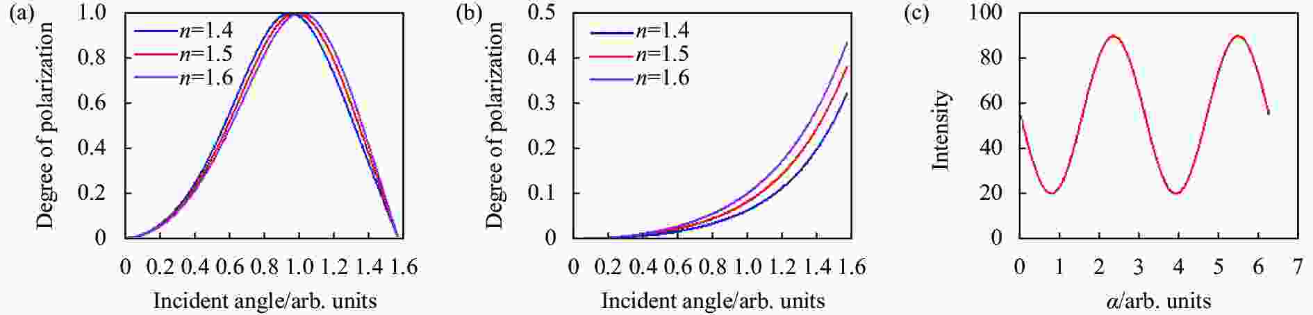
图 3 (a)、(b) 镜面反射光和漫反射光偏振度与入射角的关系;(c) 光强随偏振器旋转角度变化曲线
Figure 3. (a), (b) The relationship between the polarization degree and the incident angle of specular light and diffuse light; (c) The curve of light intensity with the rotation angle of polarizer
-
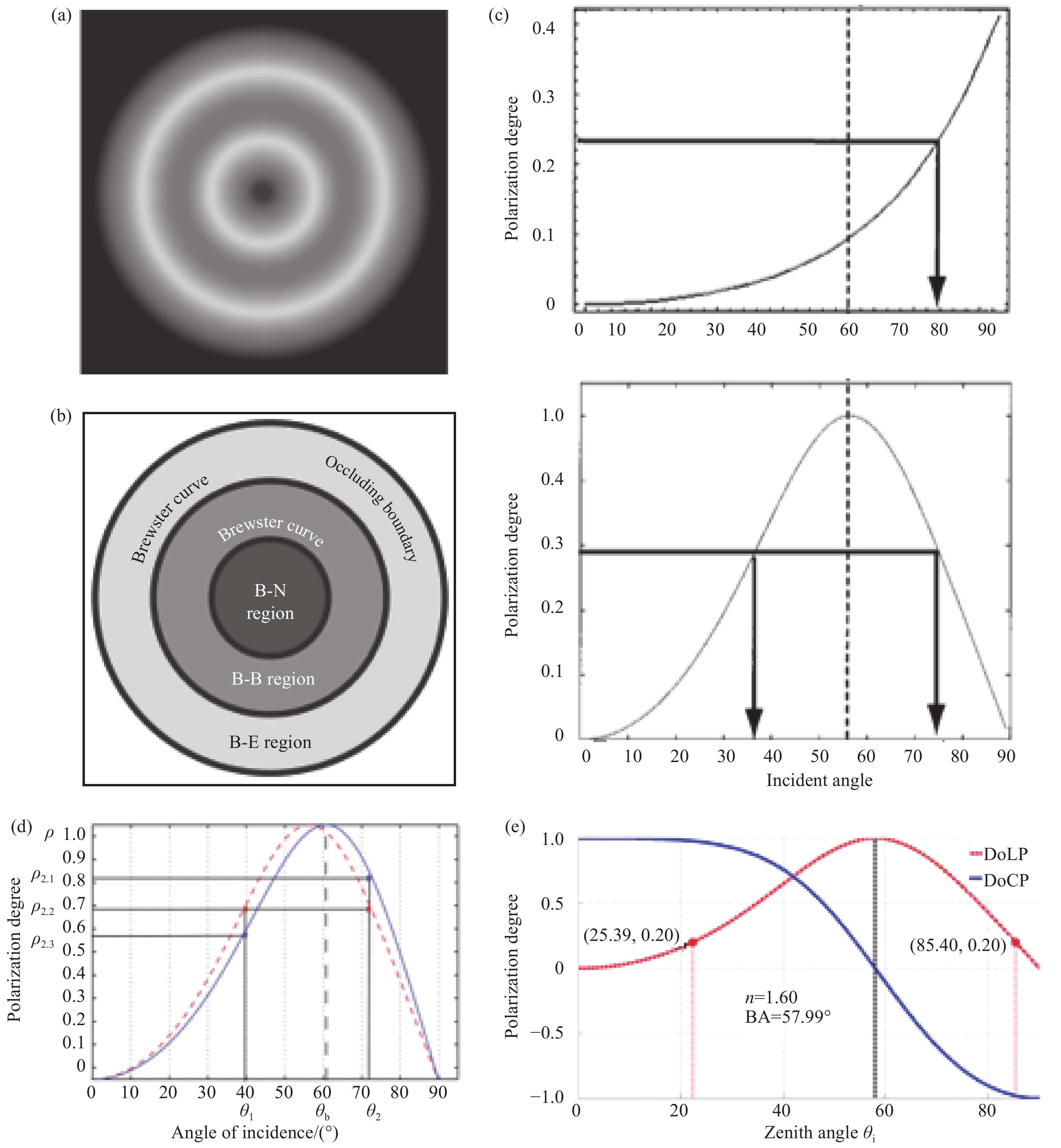
2002年,D. Miyazak等人[52]采用旋转目标测量法解决天顶角模糊问题。由图3(a)可知,当天顶角θ=0°或90°时,线偏振度为0,当天顶角为布儒斯特角时,线偏振度为1。如图4(a)~(b)所示,利用布儒斯特曲线将物体表面划分为三个区域,分别为B-E、B-B、B-N,可对天顶角进行分区域消歧。如果物体是封闭光滑的,那么解决特定区域内某一个点的模糊问题,即可完成全区域消歧。同年,D. Miyazak发现当使用红外光照明时,镜面反射光偏振度与天顶角的函数关系是单调的,如图4(c)所示,此时,通过测得光的偏振度可唯一确定天顶角。但是红外光的偏振度明显比可见光小,对于较小的入射角,偏振度很难测量。因此,将可见光和红外光相结合是处理天顶角模糊问题的有效手段[53]。2012年,C. Stolz等[54]提出用多光谱偏振处理方法得到准确的天顶角。图4(d)给出不同波段偏振度与入射角的关系,由于折射率对波长的依赖,布儒斯特角会有一定的改变,根据不同波长光照下偏振度和布儒斯特角间的差异性解决天顶角的模糊问题。实验证明,该方法能够有效重建透明物体的三维形貌。但在实际应用中,需要测量多个波段的强度值,实验装置复杂,具有一定的局限性。2015年,G. Missael等[55]提出利用圆偏振的方法处理天顶角的模糊问题。由图4(e)可知,天顶角与圆偏振度的关系为单调函数,由圆偏振度可唯一确定天顶角,解决天顶角的模糊问题。
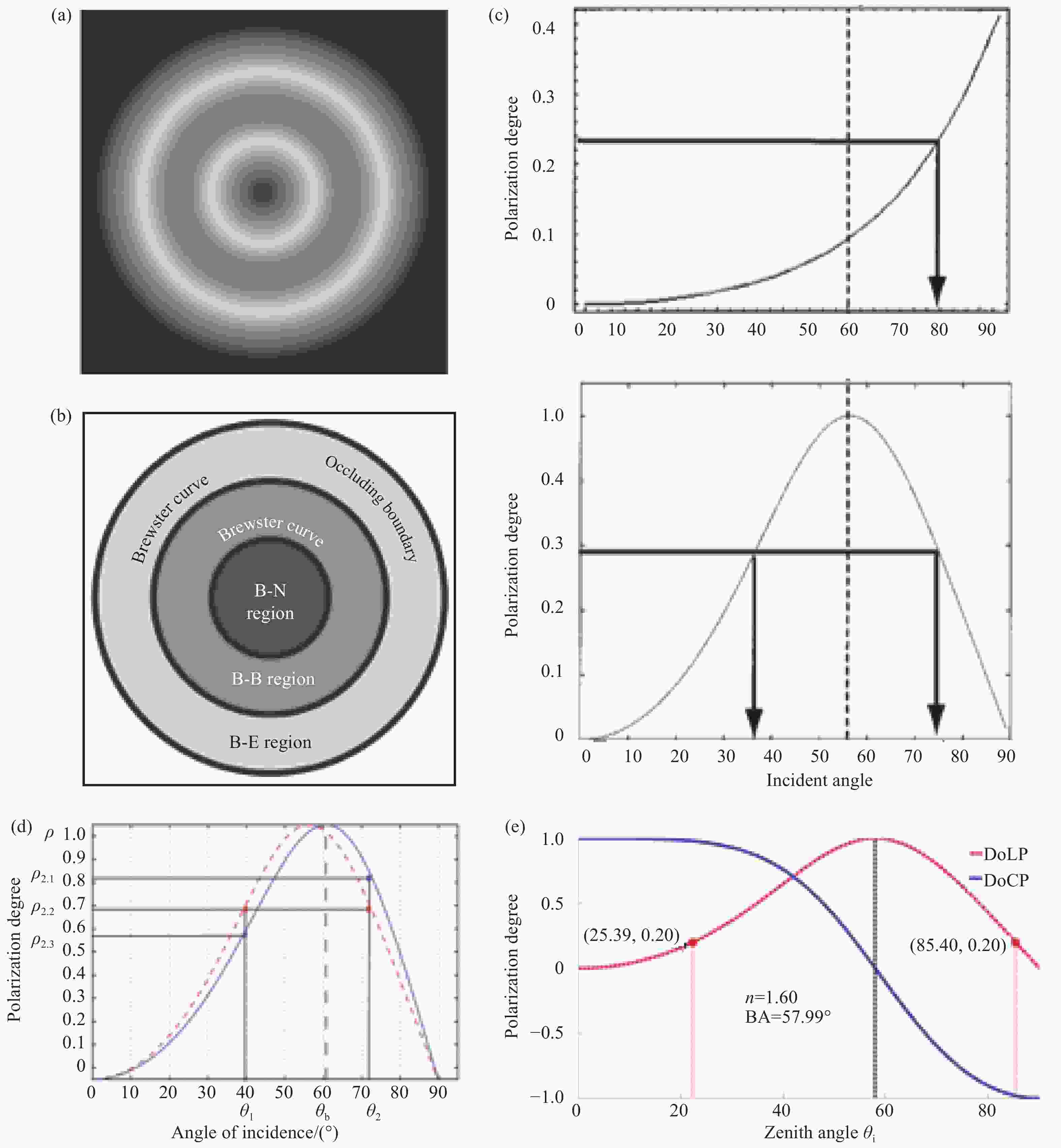
图 4 (a)(b) 布儒斯特分割[52];(c) 红外光和可见光下入射角与偏振度的关系[53];(d) 两个不同波长下入射角和偏振度关系图[54];(e) 线偏振度(DoLP)、圆偏振度(DoCP)和天顶角的关系[55]。
Figure 4. (a)(b) Brewster segmentation[52]; (c) The relationship between incident angle and polarization in infrared and visible light[53]; (d) Two degree of polarization curves simulated for two wavelengths[54]; (e) DoLP and DoCP as a function of the zenith angle[55]
-
2006年,O. Morel等[56]提出利用主动照明法消除方位角歧义,采用LED环状光源照明,为物体提供均匀的非偏振光。该光源由四部分组成,可独立控制,分别从四个方向拍摄目标,通过分析各方向的强度图像确定方位角。该方法成像过程较为复杂,且对光源和环境的要求严格。2017年,D. Miyazak等[57]提出利用偏振分析和空间雕刻法恢复目标三维形貌。首先,通过空间雕刻技术粗略估计物体的三维形貌,然后加入偏振信息实现多视角偏振三维探测。该方法充分融合空间雕刻和偏振成像方法的优势,利用奇异值分解(SVD)计算曲面法向量,使最小二乘误差最小化。可用来估计光滑物体的形状,如塑料和陶瓷物体,以及黑色和具有高镜面反射特征的彩色物体。
-
根据4.1节介绍,基于漫反射的偏振三维成像技术不存在天顶角模糊问题,因此只对方位角的消歧方法展开综述。
-
1) 结合光度立体视觉法的偏振三维成像
2007年,G. Atkinson等[58]提出利用光度立体视觉技术对方位角进行消歧。通过比较三个照明角度下拍摄图像光强的大小,实现对方位角的消歧。基于光度立体视觉的偏振三维成像技术虽然能够实现对目标形貌的三维重建,但是该方法对光源的位置要求严格,成像系统较为复杂,不易实现。
2) 结合飞行时间法(TOF)的偏振三维成像
2017年,A. Kadambi等[59]将偏振信息与飞行时间法相结合解决方位角的模糊问题。首先由Kinect(TOF相机)得到的粗糙深度获取表面法线信息Ndepth,然后结合公式(7)、(8)校正由偏振信息得到的表面法线场Npolar。2019年,北京大学杨锦发等[60]利用Astra3D相机(采用红外散斑结构光的方式)获取目标的粗糙深度图,并与偏振信息融合对方位角进行消歧,实现对光滑低纹理目标的三维重建。该方法仅适用于反射成分为漫反射的物体,应用范围有一定的局限性。此外,该方法引入了图像配准的问题,增加了三维重建的复杂度。
$$ \overset{\lower0.5em\hbox{$\smash{\scriptscriptstyle\frown}$}}{A} = \arg {\min _A}\left\| {{N^{{\rm{depth}}}} - A({N^{{\rm{polar}}}})} \right\|_2^2 A \in \left\{ {\begin{array}{*{20}{c}} { - 1}&1 \end{array}} \right\} $$ (7) $$ {N^{{\rm{corr}}}} = \overset{\lower0.5em\hbox{$\smash{\scriptscriptstyle\frown}$}}{A} ({N^{{\rm{polar}}}}) $$ (8) 3) 结合多目立体视觉法的偏振三维成像
2017年,西北工业大学平茜茜等[61]将偏振信息与双目立体视觉相结合,利用双目立体视觉法标定得到相机参数,将偏振得到的图像像素坐标系下的点云数据转化为世界坐标系下的绝对数据,实现了高反光无纹理目标真实深度的测量。2019年,D. Zhu等[62]提出偏振相机和RGB相机的混合探测系统。首先根据两相机的视差生成一个粗糙的深度图,通过计算粗糙深度图的梯度计算引导表面法线,再利用引导表面法线消除由偏振信息获取的表面法线的歧义。2021年,北京大学张瑞华[63]等采用多视角立体几何与偏振信息融合的三维重建算法消除了方位角歧义,并采用泊松优化方法纠正天顶角偏差,实现对低纹理目标形貌的三维重建。2022年,武汉大学田昕等[64]采用拟合数据项描述偏振面与融合结果之间的线性关系,将目标纹理从偏振曲面转移到融合深度中;采用鲁棒低秩矩阵分解约束双目深度和融合深度,有效地考虑了由于像素不匹配导致的缺失项和环境噪声引起的异常值的影响,提高了融合深度的精度,成像效果如图5(a)所示,但是该方法的偏振成像系统较为复杂。

图 5 成像结果。 (a) 基于偏振成像与双目立体视觉融合的三维重建[64];(b) 近红外单目偏振三维成像[66];(c) 基于稀疏线性方程组的线性深度估计[69-70];(d) 基于深度学习的偏振三维重建[72]
Figure 5. Imaging result. (a) 3D reconstruction based on fusion of polarization imaging and binocular stereo vision[64]; (b) Near-infrared monocular polarization 3D imaging[66]; (c) Linear depth estimation based on a sparse system of linear equations[69-70]; (d) Polarization 3D reconstruction based on deep learning[72]
4) 结合结构光投影的偏振三维成像
2017年,浙江大学汪凯巍等[65]采用液晶投影仪(LCD),通过在液晶两端施加不同强度的电压可快速获得具有不同偏振方向的出射光,无需旋转线偏振片进行偏振调制。该方法通过对每个结构光图的快照估计场景中的线偏振度(DoLP),通过DoLP来识别目标,并有选择性地进行重建。该方法有利于高效的三维重建和偏振目标增强。
-
2021年,西安电子科技大学韩平丽等[66]提出一种近红外单目偏振三维成像技术,该方法可直接重建非均匀反射表面的形状。在权重约束中引入参考梯度场,对非均匀反射目标表面法线的模糊进行全局校正。实验证明,该方法可以成功重构出近场和远场反射不均匀的目标形状,如图5(b)所示,并将偏振三维成像的应用扩展到复杂光照条件和较长的探测距离,分辨率为微米级。同年,西北工业大学李磊磊等[67]建立红外偏振辐射模型,该方法不依赖光照条件和目标表面的纹理特征,具有重建精度较高、实时性好和无数据空洞等优点。
-
2012年,A. Mahmoud等[68]提出将阴影恢复法与偏振信息相结合对目标实现三维重建。首先,利用偏振信息得到模糊的方位角,以可能的方位角为元素构成集合R1={φ,φ+π},然后,根据阴影信息得到的方位角构成的集合为R1={φ1,φ2}。
$$ \sum\limits_{m = {\text{1}}}^{\text{2}} {d(r,{R_m}) = } \sum\limits_{m = 1}^{\text{2}} {{{\min }_{j = 1, \ldots ,{n_m}}}\left| {r - {r_{mj}}} \right|} $$ (9) 式中:Rm(m=1,2)表示这两组中的任何一组,将集合中的元素与任意给定的r值进行比较,使得公式(9)值最小,则该元素为方位角的值。该方法假设目标表面是漫反射表面,对镜面反射像素并未处理,应用具有一定的局限性。2019年,W. Smith等[69-70]等提出通过求解大型稀疏线性方程组从单帧偏振图像中恢复表面高度。不同于其他利用偏振信息恢复表面高度的方法,该方法不需要单独进行方位角去模糊处理,因为在求解深度的线性方程组时,方位角模糊以全局最优解的方式得以解决。该方法在已知光源方向和目标表面均匀反射的情况下,首先对表面梯度进行平滑中心差分近似,然后将偏振约束和阴影约束表示为与未知深度相关的大型稀疏线性方程组的形式,最后利用线性最小二乘法对高度进行优化。W. Smith将该方法其扩展到一个未校准的室外场景,对不同材料的物体形貌均能实现三维重建,如图5(c)所示。2022年,该团队利用独立成分分析的算法将镜面反射和漫反射进行分离,然后利用朗伯体反射模型将漫反射光的强度数据转换为高度数据,再根据高度信息得到表面法线信息,最后利用公式(7)和公式(8)进行校正[71]。实验表明该方法可以达到微米级的深度分辨率。
-
2020年,Y. Ba等[72]提出深度学习结合偏振信息的方法实现目标三维重建,如图5(d)所示。该模型将0°、45°、90°、135°的偏振图像和模糊法线作为输入,通过神经网络学习,最终输出准确的表面法线。2022年,西安电子科技大学韩平丽等[73]采用基于卷积神经网络的3DMM (3D Morphable Model)模型获取每一像素的模糊表面法线,对由偏振信息得到的表面法线进行约束,从而实现了在自然光照明的环境中实现了人脸的三维重建。
目前,偏振三维成像技术已经能够实现对单一静态目标的三维重建。然而,基于镜面反射光的偏振三维成像技术中天顶角的消歧过程繁琐,无法通过一次探测确定唯一的天顶角;基于漫反射光的偏振三维成像技术存在漫反射光分量少,不易探测和镜面反射光干扰等问题,针对其方位角的模糊问题,通常需要结合其他三维感知技术获取先验信息,实现对方位角的约束,严重制约了基于漫反射光偏振三维成像技术的广泛应用。
-
超表面是一种由亚波长人造天线按照特定顺序均匀或非均匀排列而成的二维光学元件[74-75]。与传统的光学元件不同,超表面的亚波长结构与入射电磁波相互作用,引发界面上光学参量的“突变”,对电磁波的相位产生调控,进而实现对电磁波偏振转换,超表面偏振器件具有体积小、制备简单且易集成的独特优势。
近年来,随着偏振成像技术领域的蓬勃发展,高效准确的获取偏振信息成为偏振成像技术发展的关键。传统偏振元件集成度低,导致对应的偏振成像系统结构复杂、图像配准误差较大,严重制约了该领域的发展。基于超表面结构的偏振器件能够将各种偏振元件的功能集成于一体实现偏振探测,弥补了传统偏振成像系统的不足。
2018年,P.C. Wu等[76]设计了基于可见光超表面的片上偏振器件。实验证明,集成的超表面芯片可以通过单次曝光确定一组Stokes参数,覆盖可见光波段。2019年,A. Basiri等[77]设计了用于近红外偏振检测的双层手性超表面结构,总厚度小于1 μm,圆偏振器消光比高达35∶1,传输效率大于80%。将该手性超表面结构与线性偏振滤波器集成在同一芯片上,能够实现全Stokes偏振检测。该结构具有较高的消光比和传输效率,并可以直接集成到现有的成像传感器上。2020年,浙江大学徐杨和南京大学王肖沐等[78]提出并设计了由四个超表面集成石墨烯-硅光电探测器组成的片上偏振仪,该结构可以得到任意偏振入射光包括红外光(1550 nm)的光强、偏振方向等信息,获得全Stokes参数。2021年,中国科学院张冲等[79]设计并制作了用于近红外全Stokes偏振探测的高效全介电像素超表面,其工作原理见图6(a)。每个像素由三个方向的线偏振器和一个单层平面结构的圆偏振器组成,结构见图6(b),所有这些偏振器都集成在一个绝缘硅片上。设计的圆偏振滤波器在1.6 μm波长下的最大圆二色性可达70%,在波长为1.48~1.6 μm间的平均透射效率可达80%以上。2022年,西安工业大学孙雪平等[80]利用矩形TiO2纳米结构设计了正交线性和圆偏振复用超构透镜。前者能够独立控制x线偏振光和y线偏振光的聚焦位置,聚焦效率分别为53.81%和51.56%,后者对左旋圆偏振光和右旋圆偏振光聚焦效率分别可达42.45%和42.46%。

目前,国内外科学家致力于将基于超表面结构的偏振器件用于偏振成像并取得一系列研究成果。2018年,美国科学家E. Arbabi等[81]设计了一种基于介质超表面的分焦平面偏振相机,其工作原理及成像效果见图6(c)。通过在基底上设计非晶硅天线结构,具有三组不同的的偏振基可以分别得到(I0,I90)、(I45,I-45)、(Il,Ir)三组正交偏振态。将三组偏振态正交的光聚焦到同一焦平面的不同位置,根据探测器接收到的强度信息,实现全偏振态的测量和偏振成像。2019年,N.A. Rubin等[82]利用矩阵傅里叶光学原理设计并制作了超表面偏振衍射光栅。当光入射到光栅上时,光栅可以将具有不同偏振信息的光进行分选并衍射到不同级次,能够在图像传感器上形成四个对应图像,见图6(d),得到的方位角图像可用于三维成像。2022年,该团队[83]具体描述了如何将超表面偏振光栅和传统的光强度成像系统相结合以创建一个能够实现全Stokes偏振测量的系统。2020年,中国科学院宋国峰团队[84]利用金棒和SiO2薄膜组成的单层金属超表面实现了0°、45°和90°偏光器的功能,入射光波长为1.6 μm时,平均消光比均为33 dB,工作带宽为100 nm。此外,添加SiO2间隔层和U型金纳米结构组成双层金属超表面作为圆偏振器,在1.6 μm波长下透射模式下的圆偏光二色性达到89%,消光比为830∶1。由四个小像素组成的全Stokes超级像素可以实现对1.6 μm波长任意偏振光的测量。该结构有望与红外焦平面探测器集成,推动红外偏振探测器的发展。
-
文中主要从偏振探测和成像应用两方面对偏振成像技术进行综述。首先比较分析了传统的偏振成像系统,其中,分焦平面型偏振成像系统由于实时性高、集成性好等优点成为当前传统偏振成像的研究热点,但其仍存在偏振阵列消光比低和图像融合算法适用性差等缺点。基于传统的偏振成像系统,偏振二维成像技术和偏振三维成像技术被国内外科学家深入研究并取得了巨大进展。文中详细介绍了基于偏振差分和图像融合的偏振二维成像技术。偏振二维成像技术在水下和雾霾环境中取得了良好的成像效果,但是在散射因子高的环境中成像和对高、低偏振度目标的分离仍然是需要克服的难题。对于偏振三维成像技术,文中对成像过程中解决方位角和天顶角多值性问题的方法进行详细介绍。虽然当前已经可以实现对自然环境中单一物体的高精度三维重建,但是恢复的是目标的相对高度而非绝对高度。此外,现有的偏振三维成像技术无法对不连续的、动态的目标实现三维形貌恢复,仍需针对这些问题展开进一步研究。随着微纳加工技术和集成技术的不断发展进步,体积更小、集成度更高的超表面结构被国内外科学家研究应用于偏振探测。文中最后对基于超表面结构的偏振器件实现全偏振探测进行介绍,并介绍了超表面偏振器件在成像领域中的应用。
针对偏振成像过程中存在的问题,在未来的工作中,需要从以下四个方向进行深入研究:1)优化偏振成像系统。从光源的选择、偏振光的传输、偏振光的调制、偏振光的获取及偏振光的处理五个部分进行优化,减少各个环节中带来的误差; 2)改进偏振器件和探测器的集成工艺。无论是基于金属线栅的微偏振阵列还是基于超表面结构的偏振器件,高精度的集成工艺能够显著减少像元间的串扰,提高消光比。此外,如何将超表面偏振器件与传统的强度探测器相结合以增强偏振探测能力也是未来需要攻克的难题;3)增强算法的普适性和降低算法复杂度。偏振二维成像中需要采用更为鲁棒且效果更好的算法对偏振特征图像进行处理,提取视场中目标更多的信息。偏振三维成像中尽可能减少对其它方法的依赖,研究仅以偏振信息为主的算法实现目标的三维重建;4)实现高实时偏振探测。随着三维探测在各领域的应用范围不断增加,偏振三维成像技术仅能实现静态且单一连续目标的三维重建已经不能满足实际的应用需求。可以通过改进以下几个方面实现实时探测:提高图像获取速率;减少三维重建所需偏振子图像的数量;避免利用其他设备获取先验信息。以上均是偏振成像过程中亟待解决的的难题,合理有效地综合各种先进工艺和方法实现高实时偏振探测是未来偏振成像技术的重要发展方向。
Research, application and progress of optical polarization imaging technology
-
摘要: 偏振成像技术作为一种新型的光学成像技术,可以实现抑制背景噪声、提高探测距离、获取目标细节特征和识别伪装目标等功能。由于成像空间维度的不同,偏振二维成像和偏振三维成像在不同领域中具有良好的应用前景。文中从偏振光的表示与传播方式入手,先后对偏振成像系统、偏振二维成像技术、偏振三维成像技术和基于超表面偏振器件的偏振探测及成像的研究展开综述。首先,根据偏振成像系统结构的不同,偏振成像系统可分为分时型、分振幅型、分孔径型和分焦平面型四种,并对以上偏振成像系统分别进行详细介绍和比较分析。其次,阐述了基于图像增强技术的偏振二维成像。图像增强技术分为偏振差分算法和图像融合两种。对于偏振三维成像,根据所处理反射光成分的不同,分为基于镜面反射光和漫反射光的偏振三维成像。综述了三维形貌重建过程中天顶角和方位角多值性问题的解决办法。为了高效准确地获取偏振信息,基于超表面结构的偏振器件成为当前研究的热点。进一步介绍了基于超表面偏振器件的偏振探测及成像技术。最后,总结全文并对偏振成像技术的发展前景进行展望。Abstract:
Significance Traditionally, light intensity was utilized in optical imaging, resulting in multi-dimensional physical quantities such as spectrum, polarization and phase, and the light field information are lost, which lead to the poor performance or even failure of the traditional method in harsh conditions. However, polarization imaging technology utilizes the polarization property of light, which is insensitive to background illumination, ambient temperature and contrast. Meanwhile, polarization characteristic of light can be reserved more probably in low than that of the light intensity, and so it is more applicable to achieve effective detection of targets in special environments. Based on the unique advantages of polarization imaging, the technology is widely used in the fields of communication, imaging and detection. Progress Firstly, four types of traditional polarization imaging systems of time-sharing (TS), division-of-amplitude (DOA), division-of-aperture (DoAp) and division-of-focal-plane (DoFP) are introduced. Except for the TS polarizaition imaging method, the other three methods all performed well in real-time imaging. The TS polarization imaging system is simple in structure and is commonly used in polarization differential imaging and 3D imaging. The DOA polarization imaging system is relatively complex and difficult to calibrate, resulting in its poor practicality. Structure of DoAp polarization imaging system is relatively compact, but the image alignment is relatively complicated. The DoFP polarization imaging system became a focus in recent researches, owing to its advantages of low energy loss, compact structure and fast imaging. For this technology, low extinction ratio of the micro-polarization array produced during the fabrication process was significantly improved with the enormous progress in processing technology and this approach is most likely to be predominant in future polarization imaging.Based on the traditional polarization imaging system, polarization 2D/3D imaging technology has been studied and made great progress. Based on polarization difference and image fusion, the polarization 2D imaging technique that has achieved good imaging results in underwater and haze environments is illustrated in detail. 2D imaging through strong scattering media and separation of high and low polarization targets are still challenging at present. For polarization 3D imaging technology, this paper provides a detailed description of the methods to solve the azimuth and zenith angle multivalence problems in the imaging process. Although high-precision 3D reconstruction of a single object in the natural environment is currently possible, the relative height of the target rather than the absolute height is recovered (Fig.5). In addition, with the existing polarization 3D imaging technology, it is unable to achieve 3D shape recovery for discontinuous and dynamic targets, and further research is still indispensable to solve these problems.With the development of micro-nano processing and integration technology, smaller and more integrated metasurface structures have been studied and applied to polarization detection. At present, full polarization detection, and polarization imaging has been realized by using polarization devices based metasurface (Fig.6). Conclusions and Prospects Polarization imaging technology is elaborated in two aspects of polarization detection and imaging. For polarization detection, four traditional polarization imaging systems were introduced respectively. Therein, the DoFP polarization imaging system has drawn more attention due to its unique advantages of fast imaging speed and good integration. Depending on the spatial dimension, polarization 2D/3D imaging based on the traditional polarization imaging system have good prospects for detection and imaging in different fields. In order to achieve polarization detection and imaging more efficiently and conveniently, polarization devices based metasurface are fabricated and applied. Scientists at home and abroad are dedicated to continuously optimize the imaging process from five aspects of generation, transmission, modulation, acquisition and processing of polarized light, and various advanced processes and methods are effectively combined to achieve on-line polarization imaging with high stability. -
Key words:
- optical imaging /
- 2D polarization imaging /
- 3D polarization imaging /
- metasurface
-

图 3 (a)、(b) 镜面反射光和漫反射光偏振度与入射角的关系;(c) 光强随偏振器旋转角度变化曲线
Figure 3. (a), (b) The relationship between the polarization degree and the incident angle of specular light and diffuse light; (c) The curve of light intensity with the rotation angle of polarizer
图 4 (a)(b) 布儒斯特分割[52];(c) 红外光和可见光下入射角与偏振度的关系[53];(d) 两个不同波长下入射角和偏振度关系图[54];(e) 线偏振度(DoLP)、圆偏振度(DoCP)和天顶角的关系[55]。
Figure 4. (a)(b) Brewster segmentation[52]; (c) The relationship between incident angle and polarization in infrared and visible light[53]; (d) Two degree of polarization curves simulated for two wavelengths[54]; (e) DoLP and DoCP as a function of the zenith angle[55]
图 5 成像结果。 (a) 基于偏振成像与双目立体视觉融合的三维重建[64];(b) 近红外单目偏振三维成像[66];(c) 基于稀疏线性方程组的线性深度估计[69-70];(d) 基于深度学习的偏振三维重建[72]
Figure 5. Imaging result. (a) 3D reconstruction based on fusion of polarization imaging and binocular stereo vision[64]; (b) Near-infrared monocular polarization 3D imaging[66]; (c) Linear depth estimation based on a sparse system of linear equations[69-70]; (d) Polarization 3D reconstruction based on deep learning[72]
-
[1] Short N J, Yuffa A J, Videen G W, et al. Effects of surface materials on polarimetric-thermal measurements: applications to face recognition [J]. Applied Optics, 2016, 55(19): 5226-5233. doi: 10.1364/AO.55.005226 [2] Gurton K P, Yuffa A J, Videen G W. Enhanced facial recognition for thermal imagery using polarimetric imaging [J]. Optics Letters, 2014, 39(13): 3857-3859. doi: 10.1364/OL.39.003857 [3] Wang Y, Yang C, Wang Y, et al. Gigabit polarization division multiplexing in visible light communication [J]. Optics Letters, 2014, 39(7): 1823-1826. doi: 10.1364/OL.39.001823 [4] Gaiarin S, Perego A, Silva E, et al. Dual-polarization nonlinear Fourier transform-based optical communication system [J]. Optica, 2018, 5(3): 263-270. doi: 10.1364/OPTICA.5.000263 [5] He C, He H, Chang J, et al. Polarisation optics for biomedical and clinical applications: a review [J]. Light: Science & Applications, 2021, 10: 194. doi: 10.1038/s41377-021-00639-x [6] Liu Y, He H, Wu J. Differentiation of human GBM from non-gbm brain tissue with polarization imaging technique [J]. Frontiers in Oncology, 2022, 12: 863682. doi: 10.3389/fonc.2022.863682 [7] Kim M, Keller D, Bustamante C. Differential polarization imaging. I. Theory [J]. Biophysical Journal, 1987, 52(6): 911-927. doi: 10.1016/S0006-3495(87)83285-X [8] Rowe M P, Pugh E N, Tyo J S, et al. Polarization-difference imaging a biologically inspired technique for observation through scattering media [J]. Optics Letters, 1995, 20(6): 608-610. doi: 10.1364/OL.20.000608 [9] 陈伟力, 王霞, 金伟其, 等. 采用中波红外偏振成像的目标探测实验[J]. 红外与激光工程, 2011, 40(1): 7-11. doi: 10.3969/j.issn.1007-2276.2011.01.002 Chen Weili, Wang Xia, Jin Weiqi, et al. Experiment of target detection based on medium infrared polarization imaging [J]. Infrared and Laser Engineering, 2011, 40(1): 7-11. (in Chinese) doi: 10.3969/j.issn.1007-2276.2011.01.002 [10] Yang F, Wei H. Fusion of infrared polarization and intensity images using support value transform and fuzzy combination rules [J]. Infrared Physics & Technology, 2013, 60: 235-243. doi: 10.1016/j.infrared.2013.05.008 [11] Hu H, Zhao L, Li X, et al. Polarimetric image recovery in turbid media employing circularly polarized light [J]. Optics Express, 2018, 26(19): 25047-25059. doi: 10.1364/OE.26.025047 [12] Liu F, Wei Y, Han P, et al. Polarization-based exploration for clear underwater vision in natural illumination [J]. Optics Express, 2019, 27(3): 3629-3641. doi: 10.1364/OE.27.003629 [13] Liu F, Cao L, Shao X, et al. Polarimetric dehazing utilizing spatial frequency segregation of images [J]. Applied Optics, 2015, 54(27): 8116-8122. doi: 10.1364/AO.54.008116 [14] Qu Y, Zou Z. Non-sky polarization-based dehazing algorithm for non-specular objects using polarization difference and global scene feature [J]. Optics Express, 2017, 25(21): 25004-25022. doi: 10.1364/OE.25.025004 [15] Frankot R T, Chellappa R. A method for enforcing integrability in shape from shading algorithms [J]. IEEE Transactions on Pattern Analysis and Machine Intelligence, 1988, 10(4): 439-451. doi: 10.1109/34.3909 [16] 赵群, 李志宏, 杨进华. 基于松弛迭代法实现物体三维结构的重建[J]. 长春理工大学学报, 2008, 31(2): 7-10. doi: 10.3969/j.issn.1672-9870.2008.02.003 Zhao Q, Li Z H, Yang J H. 3D surface reconstruction base on relaxation method [J]. Journal of Changchun University of Science and Technology (Natural Science Edition), 2008, 31(2): 7-10. (in Chinese) doi: 10.3969/j.issn.1672-9870.2008.02.003 [17] Kovesi P. Shapelets correlated with surface normals produce surfaces[C]//10th IEEE International Conference on Computer Vision (ICCV 2005), 2005: 994-1001. [18] Atkinson G A, Hancock E R. Atkinson E R H. Recovery of surface orientation from diffuse polarization [J]. IEEE Transactions on Image Processing, 2006, 15(6): 1653-1664. doi: 10.1109/TIP.2006.871114 [19] Peterson J Q, Jensena G L, Kristib J A, et al. Polarimetric imaging using a continuously spinning polarizer element[C]// Polarization Analysis, Measurement, and Remote Sensing III, 2000, 4133: 292-300. [20] Bigué L, Cheney N. High-speed portable polarimeter using a ferroelectric liquid crystal modulator[C]//Conference on Polarization Science and Remote Sensing III, 2007, 6682: 668205. [21] Gendre L, Foulonneau A, Bigué L. Stokes imaging polarimetry using a single ferroelectric liquid crystal modulator[C]//Proceedings of SPIE, 2010, 7672: 76720B. [22] Azzam R M A. Division-of-amplitude Photopolarimeter (DOAP) for the simultaneous measurement of all four stokes parameters of light [J]. Optica Acta:International Journal of Optics, 1982, 29(5): 685-689. doi: 10.1080/713820903 [23] Phenis A M, Virgen M, Leon E E. Achromatic instantaneous Stokes imaging polarimeter[C]//Novel Optical Systems Design and Optimization VIII, 2005, 5875: 587502. [24] Mudge J, Virgen M, Dean P. Near-infrared simultaneous Stokes imaging polarimeter[C]//Conference on Polarization Science and Remote Sensing IV, 2009, 7461: 74610L. [25] Mudge J, Virgen M. Near-infrared simultaneous Stokes imaging polarimeter: integration, field acquisitions, and instrument error estimation[C]//Conference on Polarization Science and Remote Sensing V, 2011, 8160: 81600B. [26] Wang Y, Hu X, Lian J, et al. Geometric calibration algorithm of polarization camera using planar patterns [J]. Journal of Shanghai Jiaotong University (Science), 2017, 22(1): 55-59. doi: 10.1007/s12204-017-1799-3 [27] Pezzaniti J L, Chenault D B. A division of aperture MWIR imaging polarimeter[C]//Polarization Science and Remote Sensing II, 2005, 5888: 58880V. [28] Liu X, Zhai S, Li J, et al. Design of cooled medium-wave infrared polarization imaging optical system [J]. Infrared and Laser Engineering, 2021, 50(2): 20200208. (in Chinese) doi: 10.3788/irla20200208 [29] Luo H, Zhang J, Gai X, et al. Development status and prospects of polarization imaging technology (Invited) [J]. Infrared and Laser Engineering, 2022, 51(1): 20210987. (in Chinese) doi: 10.3788/IRLA20210987 [30] 罗海波, 刘燕德, 兰乐佳, 等. 分焦平面偏振成像关键技术[J]. 华东交通大学学报, 2017, 34(1): 8-13. Luo Haibo, Liu Yande, Lan Lejia, et al. Key technologies of polarization lmaging for division of focalplane polarimeters [J]. Journal of East China Jiaotong University, 2017, 34(1): 8-13. (in Chinese) [31] Nordin G P, Meier J T, Deguzman P C, et al. Micropolarizer array for infrared imaging polarimetry [J]. Journal of the Optical Society of America A-Optics Image Science and Vision, 1999, 16(5): 1168-1174. doi: 10.1364/JOSAA.16.001168 [32] Perkins R, Gruev V. Signal-to-noise analysis of Stokes parameters in division of focal plane polarimeters [J]. Optics Express, 2010, 18(25): 25815-25824. doi: 10.1364/OE.18.025815 [33] Zhao X, Bermak A, Boussaid F, et al. Liquid-crystal micropolarimeter array for full Stokes polarization imaging in visible spectrum [J]. Optics Express, 2010, 18(17): 17776-17787. doi: 10.1364/OE.18.017776 [34] Rebhan D, Rosenberger M, Notni G. Principle investigations on polarization image sensors[C]//Photonics and Education in Measurement Science 2019, 11144: 111440A. [35] Tyo J S, Rowe M P, Pugh EN, et al. Target detection in optically scattering media by polarization-difference imaging [J]. Applied Optics, 1996, 35(11): 1855-1870. doi: 10.1364/AO.35.001855 [36] Treibitz T, Schechner Y Y. Active polarization descattering [J]. IEEE Transactions on Pattern Analysis and Machine Intelligence, 2009, 31(3): 385-399. doi: 10.1109/TPAMI.2008.85 [37] Huang B, Liu T, Hu H, et al. Underwater image recovery considering polarization effects of objects [J]. Optics Express, 2016, 24(9): 9826-9838. doi: 10.1364/OE.24.009826 [38] Wang J, Wan M, Gu G, et al. Periodic integration-based polarization differential imaging for underwater image restoration [J]. Optics and Lasers in Engineering, 2022, 149: 106785. doi: 10.1016/j.optlaseng.2021.106785 [39] Schechner YY, Narasimhan S G, Nayar S K. Instant dehazing of images using polarization[C]//Conference on Computer Vision and Pattern Recognition, 2001: 325-332. [40] Schechner Y Y, Narasimhan S G, Nayar S K. Polarization-based vision through haze [J]. Applied Optics, 2003, 42(3): 511-525. doi: 10.1364/AO.42.000511 [41] Fang S, Xia X, Huo X, et al. Image dehazing using polarization effects of objects and airlight [J]. Optics Express, 2014, 22(16): 19523-19537. doi: 10.1364/OE.22.019523 [42] Cao L, Shao X, Liu F, et al. Dehazing method through polarimetric imaging and multi-scale analysis[C]//Conference on Satellite Data Compression, Communications, and Processing XI, 2015, 9501: 950111. [43] Lavigne D A, Breton M. A new fusion algorithm for shadow penetration using visible and midwave infrared polarimetric images[C]//2010 13th International Conference on Information Fusion, 2010:1-7. [44] Zhou P, Wang F, Zhang H, et al. Camouflaged target detection based on visible and near infrared polarimetric imagery fusion[C]//International Symposium on Photoelectronic Detection and Imaging 2011: Advances in Imaging Detectors and Applications, 2011, 8194: 81940Y. [45] Liu Z, Zeng H, Wang H, et al. Visible polarization image fusion with non-subsampled Shearlets[C]//International Conference on Frontiers in Optical Imaging Technology and Applications, 2015, 9795: 97951S [46] Liang J, Zhang W, Ren L, et al. Polarimetric dehazing method for visibility improvement based on visible and infrared image fusion [J]. Applied Optics, 2016, 55(29): 8221-8226. doi: 10.1364/AO.55.008221 [47] Yan X, Qin H, Li J, et al. Infrared and visible image fusion using multiscale directional nonlocal means filter [J]. Applied Optics, 2015, 54(13): 4299-4308. doi: 10.1364/AO.54.004299 [48] Zhang J, Shao J, Chen J, et al. Polarization image fusion with self-learned fusion strategy [J]. Pattern Recognition, 2021, 118: 108045. doi: 10.1016/j.patcog.2021.108045 [49] Zhang J, Zhang X, Li T, et al. Visible light polarization image desmogging via cycle convolutional neural network [J]. Multimedia Systems, 2021, 28(1): 45-55. doi: 10.1007/s00530-021-00802-9 [50] Shen H, Zheng Z. Real-time highlight removal using intensity ratio [J]. Applied Optics, 2013, 52(19): 4483-4493. doi: 10.1364/AO.52.004483 [51] Wolff L B, Boult T E. Constraining object features using a polarization reflectance model [J]. IEEE Transactions on Pattern Analysis and Machine Intelligence, 1991, 13(7): 635-657. doi: 10.1109/34.85655 [52] Miyazak D, Kagesawa M, Ikeuchi K. Determining shapes of transparent objects from two polarization images[C]//Proceedings of the IAPR Conference on Machine Vision Applications (IAPR MVA 2002), 2002: 26-31. [53] Miyazaki D, Saito M, Sato Y, et al. Determining surface orientations of transparent objects based on polarization degrees in visible and infrared wavelengths [J]. Journal of the Optical Society of America A-Optics Image Science and Vision, 2002, 19(4): 687-694. doi: 10.1364/JOSAA.19.000687 [54] Stolz C, Ferraton M, Meriaudeau F. Shape from polarization a method for solving zenithal angle ambiguity [J]. Optics Letters, 2012, 37(20): 4218-4220. doi: 10.1364/OL.37.004218 [55] Garcia N M, Erausquin I d, Edmiston C, et al. Surface normal reconstruction using circularly polarized light [J]. Optics Express, 2015, 23(11): 14391-14406. doi: 10.1364/OE.23.014391 [56] Morel O, Stolz C, Meriaudeau F, et al. Active lighting applied to three-dimensional reconstruction of specular metallic surfaces by polarization imaging [J]. Applied Optics, 2006, 45(17): 4062-4068. doi: 10.1364/AO.45.004062 [57] Miyazaki D, Shigetomi T, Baba M, et al. Surface normal estimation of black specular objects from multiview polarization images [J]. Optical Engineering, 2017, 56(4): 1-17. doi: 10.1117/1.Oe.56.4.041303 [58] Gary A. Atkinson E R H. Surface reconstruction using polarization and photometric stereo[C]//12th International Conference on Computer Analysis of Images and Patterns, 2007, 4673(58): 466-473. [59] Kadambi A, Taamazyan V, Shi B, et al. Depth sensing using geometrically constrained polarization normals[C]//IEEE International Conference on Computer Vision (ICCV), 2017. 125(1-3): 34-51. [60] 杨锦发, 晏磊, 赵红颖, 等. 融合粗糙深度信息的低纹理物体偏振三维重建[J]. 红外与毫米波学报, 2019, 38(6): 819-827. doi: 10.11972/j.issn.1001-9014.2019.06.020 Yang J, Yan L, Zhao H, et al. Shape from polarization of low-texture objects with rough depth information [J]. J Infrared Millim Waves, 2019, 38(6): 819-827. (in Chinese) doi: 10.11972/j.issn.1001-9014.2019.06.020 [61] 平茜茜, 刘勇, 董欣明, 等. 基于偏振双目视觉的无纹理高反光目标三维重构[J]. 红外与毫米波学报, 2017, 36(4): 432-438. doi: 10.11972/j.issn.1001-9014.2017.04.009 Ping X, Liu Y, Dong X, et al. 3-D reconstruction of textureless and high-reflective target by polarization and binocular stereo vision [J]. J Infrared Millim Waves, 2017, 36(4): 432-438. (in Chinese) doi: 10.11972/j.issn.1001-9014.2017.04.009 [62] Zhu D, Smith W A P. Depth from a polarisation + RGB stereo pair[C]//IEEE/CVF Conference on Computer Vision and Pattern Recognition (CVPR), 2019: 7569-7578. [63] 张瑞华, 施柏鑫, 杨锦发, 等. 基于视差角和天顶角优化的偏振多视角三维重建[J]. 红外与毫米波学报, 2021, 40(1): 133-142. doi: 10.11972/j.issn.1001-9014.2021.01.018 Zhang R, Shi B, Yang J, et al. Polarimetric multi-view 3D reconstruction based on parallax angle and zenith angle optimization [J]. J Infrared Millim Waves, 2021, 40(1): 133-142. (in Chinese) doi: 10.11972/j.issn.1001-9014.2021.01.018 [64] Tian X, Liu R, Wang Z, et al. High quality 3D reconstruction based on fusion of polarization imaging and binocular stereo vision [J]. Information Fusion, 2022, 77: 19-28. doi: 10.1016/j.inffus.2021.07.002 [65] Huang X, Bai J, Wang K, et al. Target enhanced 3D reconstruction based on polarization-coded structured light [J]. Optics Express, 2017, 25(2): 1173-1184. doi: 10.1364/OE.25.001173 [66] Li X, Liu F, Shao X. Near-infrared monocular 3D computational polarization imaging of surfaces exhibiting nonuniform reflectance [J]. Optics Express, 2021, 29(10): 15616-15630. doi: 10.1364/OE.423790 [67] 李磊磊, 黄海霞, 郭阳, 等. 基于红外辐射偏振成像的目标三维重建方法[J]. 红外与毫米波学报, 2021, 40(3): 413-419. doi: 10.11972/j.issn.1001-9014.2021.03.018 Leilei L, Haixia H, Yang G, et al. 3D reconstruction method of target based on infrared radiation polarization imaging [J]. J Infrared Millim Waves, 2021, 40(3): 413-419. (in Chinese) doi: 10.11972/j.issn.1001-9014.2021.03.018 [68] Mahmoud A H, El-Melegy M T, Farag A A. Direct method for shape recovery from polarization and shading[C]//19th IEEE International Conference on Image Processing (ICIP), 2012: 1769-1772. [69] Smith WAP, Ramamoorthi R, Tozza S. Linear depth estimation from an uncalibrated, monocular polarisation image[C]//14th European Conference on Computer Vision (ECCV), 2016, 9912: 109-125. [70] Smith W A P, Ramamoorthi R, Tozza S. Height-from-polarisation with unknown lighting or albedo [J]. IEEE Trans Pattern Anal Mach Intell, 2019, 41(12): 2875-2888. doi: 10.1109/TPAMI.2018.2868065 [71] Han P, Cai Y, Liu F, et al. Computational polarization 3D: New solution for monocular shape recovery in natural conditions [J]. Optics and Lasers in Engineering, 2022, 151: 106925. doi: 10.1016/j.optlaseng.2021.106925 [72] Ba Y, Gilbert A, Wang F, et al. Deep shape from polarization[C]//ECCV 2020: Computer Vision – ECCV 2020, 2020, 12369: 554-571. [73] Han P, Li X, Liu F, et al. Accurate passive 3D polarization face reconstruction under complex conditions assisted with deep learning [J]. Photonics, 2022, 9(12): 1-12. doi: 10.3390/photonics9120924 [74] Ding F, Chen Y, Bozhevolnyi S I. Metasurface-based polarimeters [J]. Applied Sciences, 2018, 8(4): 594. doi: 10.3390/app8040594 [75] 倪一博, 闻顺, 沈子程, 等. 基于超构表面的多维光场感知[J]. 中国激光, 2021, 48(19):1-28. doi: 10.3788/CJL202148.1918003 Ni Y B, Wen S, Shen Z C, et al. Multidimensional light field sensing based on metasurfaces [J]. Chinese Journal of Lasers, 2021, 48(19): 1918003. (in Chinese) doi: 10.3788/CJL202148.1918003 [76] Wu P C, Chen J W, Yin C W, et al. Visible metasurfaces for on-chip polarimetry [J]. ACS Photonics, 2018, 5(7): 2568-2573. doi: 10.1021/acsphotonics.7b01527 [77] Basiri A, Chen X, Bai J, et al. Nature-inspired chiral metasurfaces for circular polarization detection and full-Stokes polarimetric measurements [J]. Light: Science & Applications, 2019, 8: 78. doi: 10.1038/s41377-019-0184-48 [78] Li L, Wang J, Kang L, et al. Monolithic full-stokes near-infrared polarimetry with chiral plasmonic metasurface integrated graphene-silicon photodetector [J]. ACS Nano, 2020, 14(12): 16634-16642. doi: 10.1021/acsnano.0c00724 [79] Zhang C, Hu J, Dong Y, et al. High efficiency all-dielectric pixelated metasurface for near-infrared full-Stokes polarization detection [J]. Photonics Research, 2021, 9(4): 583-589. doi: 10.1364/PRJ.415342 [80] Sun X, Ma R, Pu X, et al. High-efficiency polarization multiplexing metalenses [J]. Nanomaterials (Basel), 2022, 12(9): 1-9. doi: 10.3390/nano12091500 [81] Arbabi E, Kamali S M, Arbabi A, et al. Full-stokes imaging polarimetry using dielectric metasurfaces [J]. ACS Photonics, 2018, 5(8): 3132-3140. doi: 10.1021/acsphotonics.8b00362 [82] Rubin N A, D'Aversa G, Chevalier P, et al. Matrix fourier optics enables a compact full-stokes polarization camera [J]. Science, 2019, 365(6448): 1-8. doi: 10.1126/science.aax1839 [83] Rubin N A, Chevalier P, Juhl M, et al. Imaging polarimetry through metasurface polarization gratings [J]. Optics Express, 2022, 30(6): 9389-9412. doi: 10.1364/OE.450941 [84] Cheng B, Zou Y, Shao H, et al. Full-Stokes imaging polarimetry based on a metallic metasurface [J]. Optics Express, 2020, 28(19): 27324-27336. doi: 10.1364/OE.400622 -

 点击查看大图

计量
- 文章访问数: 904
- HTML全文浏览量: 92
- PDF下载量: 296
- 被引次数: 0

