


-
B-2轰炸机是当今世界上唯一一种现役隐身战略轰炸机,独特的吸波涂层和较小的雷达散射面使其具备较低的可侦测性。低的可侦测性指飞行目标可被仪器探测到的特征,包括雷达、红外线、可见光和音频信号均被降低,能增加飞行器被探测的难度[1]。例如,B-2轰炸机的雷达反射截面(Radar Cross Section, RCS)仅为0.1 m2[2],意味着通过雷达探测技术实现目标的探测与识别相对困难。然而,飞行器的高温表面和高温燃气往往难以直接隐蔽和消除,成为红外辐射主要辐射源。特别是近年来,随着红外探测技术的提升,尤其是红外探测器灵敏度的提高,为低特征目标的探测与识别提供了可能。
对类B-2型飞行器而言,红外辐射主要来自于发动机高温尾喷焰和表面蒙皮。其中,发动机尾喷焰中往往含有CO2、H2O、CO等组分,在高温下通过振-转能级跃迁可发射特定波段的红外光辐射。此外,在气动加热作用下的高温蒙皮也会发射遵循普朗克定律的连续光谱。这意味着,基于红外辐射信号对类B-2型飞行器实现探测与识别,应关注本体和喷焰的红外辐射特性及特征规律。
目前已有诸多学者对飞行器的红外辐射特征开展了研究。例如,吕建伟等[3]采用流体动力学(Computational Fluid Dynamics, CFD)方法计算飞机蒙皮温度并采用反向蒙特卡洛法(Reverse Monte Carlo, RMC)求解目标本体红外辐射特征;林杰等[4]从可视性和空间遮挡问题出发,提出一种计算蒙皮自身辐射特性的模型;程文[5]基于扩展的Malkmus窄带模型,使用视在光线法计算了飞行器羽流的红外辐射特征;徐顶国等[6]采用离散传递法计算了飞行器后机身蒙皮的红外辐射特性;郑乾刚等[7]建立了涡扇发动机排气系统红外辐射强度的预测模型。前人针对飞行器的辐射特性研究,多关注本体或喷焰,且以导弹喷焰和战斗机为主,而对B-2类新颖气动布局隐身飞行器的本体与喷焰耦合红外辐射特性研究少见。
文中以类B-2型飞行器为研究对象,围绕飞行器本体壁面和尾喷焰参与条件下的红外辐射特性分布规律展开研究,建立考虑壁面遮挡效应的本体和喷焰辐射传输计算模型,分析典型飞行工况下飞行器在不同观测角度下的红外辐射特性,包含光谱、不同谱带内积分强度和辐射强度分布。
-
B-2飞行器采用F-118非加力涡扇发动机,涵道比为0.8,发动机结构和系统与F110类似[8],发动机的内部结构及内涵道气体状态如图1所示。为计算尾焰流场分布特性,采用分段定比热法和理想气体状态假设结合的方法预估发动机喷口流动和热力特性参数。

图 1 发动机内部结构及内涵道气体状态示意图
Figure 1. The internal structure of engine and the gas states of the inner channel
结合等熵绝热过程计算方法,尾喷管出口截面静温计算可由下式获得:
$$ {T_9} = {T_{{t_9}}}{\left( {1 + \frac{{{k_{\text{g}}} - 1}}{2}M{a_\infty }^2} \right)^{ - 1}} $$ (1) 式中:$ {k_{\text{g}}} $为燃气的比热比;$ M{a_\infty } $为来流马赫数;$ {T_{{t_9}}} $为尾喷管出口总温,由燃烧室出口总温$ {T_{{t_4}}} $逐级计算得到,其表达式为[8]:
$$ {T_{{t_9}}} = \frac{{{T_{{t_6}}}}}{{{T_{{t_5}}}}} \cdot \frac{{{T_{{t_5}}}}}{{{T_{{t_{4{\text{C}}}}}}}} \cdot \left( {{\tau _{{{\text{m}}_{\text{2}}}}} \cdot \frac{{{T_{{t_{4.5}}}}}}{{{T_{{t_{4{\text{a}}}}}}}}} \right) \cdot \left( {{\tau _{{{\text{m}}_{\text{1}}}}} \cdot {T_{{t_4}}}} \right) $$ (2) 式中:$ {\tau _{{{\text{m}}_{\text{1}}}}} $和$ {\tau _{{{\text{m}}_{\text{2}}}}} $分别为气流混合器1、2进出口总温之比。
依据文献[9],尾喷管出口速度计算方程为:
$$ {c_9} = {a_9}M{a_9} = \sqrt {{k_{\text{g}}}R{T_9}} \cdot \sqrt {\frac{2}{{{k_{\text{g}}} - 1}}\left[ {{{\left( {\frac{{{p_{{t_9}}}}}{{{p_9}}}} \right)}^{{\raise0.7ex\hbox{${{k_g} - 1}$} \mathord{\left/ {\vphantom {{{k_g} - 1} {{k_g}}}}\right.} \lower0.7ex\hbox{${{k_g}}$}}}} - 1} \right]} $$ (3) 式中:R为气体常数;取287 J/(kg·N);$ {a_9} $为尾喷管出口声速;尾喷管出口总压$ {p_{{t_9}}} $表达式为:
$$ {p_{{t_9}}} = \sigma _{{\text{b,ab}}}^2{\sigma _{\text{m}}} \cdot \frac{{{{{p_{{t_{4.5}}}}} \mathord{\left/ {\vphantom {{{p_{{t_{4.5}}}}} {{\pi _{{\text{TL}}}} + {B_{\text{m}}}{\sigma _\Pi }{p_{{t_0}}}{\sigma _{\text{i}}}{\pi _{{\text{CL}}}}}}} \right. } {{\pi _{{\text{TL}}}} + {B_{\text{m}}}{\sigma _\Pi }{p_{{t_0}}}{\sigma _{\text{i}}}{\pi _{{\text{CL}}}}}}}}{{1 + {B_{\text{m}}}}} $$ (4) 式中:$ {\sigma _{{\text{b,ab}}}} $为加力燃烧室总压恢复系数;发动机不加力时取0.98;$ {\sigma _{\text{m}}} $为混合室总压恢复系数;$ {p_{{t_{4.5}}}} $为高压涡轮出口压力;$ {\pi _{{\text{TL}}}} $为低压涡轮落压比;$ {B_{\text{m}}} $为混合室进口的涵道比;$ {\sigma _\Pi } $为外涵风扇出口至混合室进口的总压损失系数;$ {\sigma _{\text{i}}} $为进气道总压恢复系数;$ {\pi _{{\text{CL}}}} $为风扇增压比;$ {p_{{t_0}}} $为进气口截面总压,可由下式计算获得:
$$ {p_{{t_0}}} = {p_{\text{0}}}{\left( {1 + \frac{{{k_{\text{a}}} - 1}}{2}M{a_\infty }^2} \right)^{\tfrac{{{k_{\text{a}}}}}{{{k_{\text{a}}} - 1}}}} $$ (5) 式中:$ {p_0} $为大气压力;$ {k_{\text{a}}} $为空气的比热比。
-
在连续介质假设下,飞行器绕流场和发动机尾焰化学反应流场均可由真实气体表征的可压缩Navier-Stokes方程来描述。方程组包含连续方程、动量方程、能量方程和组分方程,分别如下:
连续方程:
$$ \frac{{\partial \rho }}{{\partial t}} + \frac{\partial }{{\partial {x_i}}}\left( {\rho {u_i}} \right) = 0 $$ (6) 动量方程:
$$ \frac{\partial }{{\partial t}}\left( {\rho {u_i}} \right) + \frac{\partial }{{\partial {x_k}}}\left( {\rho {u_i}{u_k}} \right) = - \frac{{\partial p}}{{\partial {x_i}}} + \frac{{\partial {\tau _{ik}}}}{{\partial {x_k}}} $$ (7) 能量方程:
$$ \frac{{\partial E}}{{\partial t}} + \frac{\partial }{{\partial {x_i}}}\left( {E{u_i} + p{u_i}} \right) = \frac{\partial }{{\partial {x_j}}}\left( {{u_j}{\tau _{ij}} + {q_i}} \right) $$ (8) 组分方程:
$$ \frac{{\partial \left( {\rho {F_s}} \right)}}{{\partial t}} + \frac{{\partial \left( {\rho {F_s}{u_j}} \right)}}{{\partial {x_j}}} = \frac{\partial }{{\partial {x_j}}}\left( {\rho {D_s}\frac{{\partial {F_s}}}{{\partial {x_j}}}} \right) + {\dot \omega _s} $$ (9) 式中:$ \rho 、u、p $分别表示流体的密度、速度和压强;$ \tau $和$ E $分别为流体粘性应力和内能;$ q $为热流;$ F $为组分的质量分数;$ D $为组分扩散系数;$ \dot \omega $为复燃化学反应引起的质量变化率;$ t $为时间;下标$ i、j、k $表示直角坐标轴的三个方向;下标s为组分种类。
总能量表示为:
$$ E = \rho e + \rho \frac{{{u_i}{u_i}}}{2} $$ (10) 黏性张量表示为:
$$ {\tau _{ij}} = \mu \left[ {\frac{{\partial {u_j}}}{{\partial {x_i}}} + \frac{{\partial {u_i}}}{{\partial {x_j}}} - \frac{2}{3}\frac{{\partial {u_k}}}{{\partial {x_k}}}{\delta _{ij}}} \right] $$ (11) 热流项表示为:
$$ {q_i} = - {k_{\text{B}}}\frac{{\partial T}}{{\partial {x_i}}} $$ (12) 式中:μ为粘度;$ {\delta }_{ij} $为Kronecker函数;$ {k_{\text{B}}} $为Boltzmann常数;T为温度。
为了折中考虑计算精度和花费,上述方程采用雷诺平均N-S(Reynolds Averaged Navier-Stokes, RANS)方法求解计算。考虑到逆压梯度边界层特性,采用剪切应力输运(Shear Stress Transport, SST)湍流模型对上述方程进行封闭处理。黏性通量计算中的导数项采用二阶中心差分格式计算,二阶迎风格式离散无黏通量,采用时间推进法求解定常流场,详细计算过程参考文献[10]。
-
飞行器的壁面热流来源于绕流场气动加热,包含对流热流项和组分扩散热流项,其表达形式为:
$$ {q_{w,n}} = \lambda \frac{{\partial T}}{{\partial n}} + \rho \sum\limits_{s = 1}^{{N_s}} {{h_s}{D_s}\frac{{\partial {Y_s}}}{{\partial n}}} $$ (13) 式中:n表示壁面的法向方向坐标。
对于壁面而言,垂直壁面方向上的热流平衡方程为:
$$ {q_{w,n}} = {q_{\text{c}}} + \sigma \varepsilon T_{\text{w}}^4 $$ (14) 式中:qc表示从壁面到机体结构内部的热传导热流;ε为表面材料发射率,文中取0.6;σ为斯蒂芬-玻耳兹曼常数,其值为5.67×10⁻⁸ W/(m2·K4);Tw为壁面温度。在不计结构导热情况下,依据辐射平衡壁面边界条件有:
$$ {q_{w,n}} = \sigma \varepsilon T_{\text{w}}^4 $$ (15) -
依据普朗克黑体定律,飞行器在λ1~λ2波段范围内的辐射出射度为:
$$ {M_{\text{b}}} = \int_{{\lambda _1}}^{{\lambda _2}} {{M_{\text{b}}}\left( \lambda \right)} {\rm{d}}\lambda = \int_{{\lambda _1}}^{{\lambda _2}} {\frac{{{c_1}}}{{{\lambda ^5}}}} \cdot \frac{1}{{{{\rm{e}}^{{c_2}/\left( {\lambda T} \right)}} - 1}}{\rm{d}}\lambda $$ (16) 式中:$ {M_{\text{b}}} $为黑体辐射出射度;$ {M_{\text{b}}}(\lambda ) $为黑体的光谱辐射出射度;第一辐射常数c1=3.741 8×10⁻¹⁶ W·m2;第二辐射常数c2=1.438 8×10⁻² m·K。飞行器表面材料发射率为ε、温度为T的微元面辐射强度为:
$$ M\left( {\lambda ,T} \right) = {{\varepsilon \left( \lambda \right) \cdot {M_{\text{b}}}\left( {\lambda ,T} \right)} \mathord{\left/ {\vphantom {{\varepsilon \left( \lambda \right) \cdot {M_{\text{b}}}\left( {\lambda ,T} \right)} \pi }} \right. } \pi } $$ (17) -
高温尾焰气体因组分的不同在发射带和吸收带内具有强烈的谱带选择性,混合气体的辐射特性依赖于各气体组元的辐射物性参数,文中仅考虑CO2、H2O、OH和CO组分。可依据NASA-SP-3080数据库[11]并结合气体温度T和波数η,插值计算吸收系数ki和谱线间隔di。
依据窄谱带模型计算方法,可获得高温燃气光谱计算所需的辐射物性参数。在窄谱带模型中,Δη光谱范围内的平均透过率可由下式计算得到:
$$ \bar \tau = \exp \left\{ { - 2a\left[ {{{\left( {1 + \frac{{\bar \kappa l}}{a}} \right)}^{{1 \mathord{\left/ {\vphantom {1 2}} \right. } 2}}} - 1} \right]} \right\} $$ (18) 式中:$ a = \pi {{\bar \gamma } \mathord{\left/ {\vphantom {{\bar \gamma } {\bar d}}} \right. } {\bar d}} $为谱带精细结构参数;$ \bar \kappa $为谱带内平均吸收系数;l为压力行程长度。
-
根据辐射传输理论,当考虑介质内的吸收、发射和散射时,辐射传输方程可表达为[12]:
$$ \frac{{{\rm{d}}{I_\lambda }\left( s \right)}}{{{\rm{d}}s}} = - {\kappa _{a\lambda }}{I_\lambda }\left( s \right) - {\kappa _{s{\text{λ }}}}{I_\lambda }\left( s \right) + {\kappa _{a\lambda }}{I_{{{b}}\lambda }}\left( s \right) $$ (19) 式中:$ {I_\lambda }(s) $和${I_{{{b}}\lambda }}(s)$表示光谱辐射强度和黑体光谱辐射强度;$ {\kappa _{a\lambda }} $和$ {\kappa _{s\lambda }} $分别为介质的吸收系数和散射系数。
在不考虑粒子散射效应下,引入光学厚度$ {\tau _\lambda } = {\kappa _{{\text{e}}\lambda }} $,辐射传输方程简化为:
$$ \frac{{{\rm{d}}{I_\lambda }\left( {{\tau _\lambda }} \right)}}{{{\rm{d}}{\tau _\lambda }}} = - {I_\lambda }\left( {{\tau _\lambda }} \right) + {I_{{{b}}\lambda }}\left( {{\tau _\lambda }} \right) $$ (20) 飞行器绕流场和尾喷焰均由气体组成,不计散射介质,可采用视在光线法(Line of Sight, LOS)[13]求解辐射传输方程。视在光线法的基本思想是将三维非均匀介质中的辐射传输简化为一维多层介质的辐射传输问题。辐射传输示意图如图2所示。平行于探测方向的LOS与流场相交时,会延续到飞行器表面或穿透流场。将流场分为i层,假设每层内介质均匀等温,则沿着射线反方向逐层积分即可计算获得该探测方向上的辐射强度与光学厚度。沿LOS的辐射强度表达为:

图 2 基于LOS方法的辐射传输计算示意图
Figure 2. Schematic diagram of radiative transfer computations using the LOS method
$$ I_\lambda ^i = I_\lambda ^{i - 1}\bar \tau _\lambda ^i + I_{{{b}},\lambda }^i\left( {1 - \bar \tau _\lambda ^i} \right) $$ (21) 式中:$ I_\lambda ^i $和$I_{{{b}},\lambda }^i$分别为第 i 层介质处波长为 λ 的辐射强度和黑体辐射强度;$ \bar \tau _\lambda ^i $为第i层的介质透过率。
在$ {\lambda _1} $和$ {\lambda _2} $波段内的辐射强度可表达为:
$$ {I_{\Delta \lambda }} = \int_{{\lambda _1}}^{{\lambda _2}} {{I_\lambda }{{\rm{d}}_\lambda }} $$ (22) -
类B-2型飞行器的外形结构尺寸可参考文献[14]获得,主要参数见表1。飞行器的进气口设在机翼上方,呈锯齿状,并具有一个带尖锐唇口外罩,进气道呈“S”状;发动机装有气流混合器,喷嘴深埋在机翼内;尾喷口宽而扁平,呈扇贝状。为了计算方便且不失飞行器的主要外形结构,以典型层流翼型NACA2412作为翼根翼型、NACA2408作为翼尖翼型。经过对飞行器各部件的外形曲面、过渡面的重构以及对曲面连接处光滑过渡处理,最后得到了类B-2型飞行器的三维模型,其几何结构如图3所示。
表 1 类B-2型飞行器主要建模参数
Table 1. Main modeling parameters of the B-2-like aircraft
Parameter Reference value Parameter Reference value Length of aircraft/m 21.03 wing area/m2 477.5 altitude of aircraft/m 5.18 Length of engine/m 2.55 Wing span/m 52.43 Maximum diameter/m 1.18 
图 3 类B-2型飞行器几何结构示意图
Figure 3. Geometry of the B-2-like aircraft
-
依据飞行器结构的对称性,为减少计算量,取1/2部分进行计算建模。计算域选取150 m (长)×40 m (宽)×60 m (高)的长方体。采用ANSYS-ICEM软件进行结构化网格划分,计算域被分为76个block,网格数约为536 万。沿机身横向、翼展和纵向方向的网格数分别为251×178×120。为准确计算壁面热流和壁面温度,在壁面附近的流体计算域内进行网格加密,贴壁第一层网格的y+≈2。飞行器对应的计算域和网格分布如图4所示。图4(a)~(d)分别为计算域及block分布、对称面上网格分布、边界层网格分布和机身壁面网格分布。
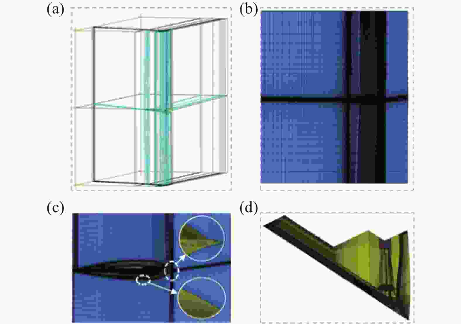
图 4 计算域及网格分布
Figure 4. Computational domain and grid distributions
-
采用ANSYS-FLUENT 16.0软件对类B-2型飞行器绕流场及尾喷焰反应流场进行仿真计算。由于采用1/2模型进行计算,需指定对称面为对称边界,该边界处法向速度及法向梯度均为零;飞行器蒙皮表面设置为辐射平衡壁面;计算域后端面施加为压力出口边界,压力取值与来流压力相同;计算域其他面指定为由来流参数描述的远场边界;喷管出口施加多组分温度边界条件。
依据文献[15],B-2飞行器的典型飞行高度为H=12 km,飞行速度为Ma=0.8。该飞行高度下环境的静温为216.7 K,静压为19386 Pa。由于缺乏F-118发动机的相关数据,在此引用F110-GE-100发动机的压比数据[16]πCL=3.2、πCH=9.7 和燃烧室出口总温$ {T_{{t_4}}} $=1427 K来类比。发动机工作过程参数参考文献[9],空气的定压比热容$ {C_p} $=1005 J/(kg∙N)、比热比${k_{{a}}}$=1.4,燃气的定压比热容$ {C_{pg}} $=1244 J/(kg∙N)、比热比$ {k_g} $=1.3。依据1.1节计算模型,可得发动机喷口静温与速度分别为625.3 K和1278.1 m/s。依据文献[17, 18],S弯喷管可使高温燃气温度降低30%左右。依据上述参数和工程近似处理,可得类B-2型飞行器尾喷口截面的燃气静温为437.7 K。假设尾喷管完全膨胀,则出口压力等于外界大气压(P∞=19386 Pa)。发动机喷口燃气组分摩尔浓度参考文献[19],分别取为N2=0.3104、H2O=0.3090、H2=0.2087、CO2=0.0930、CO=0.0789。
-
为了分析类B-2型飞行器在不同观测角度下的辐射特性,文中考虑两个垂直于飞行器对称面的探测轨道面,分别为:(1)规定绕图5中垂直于X轴的Z轴旋转面为探测轨道面1;(2)垂直于Z轴的Y轴旋转面为探测轨道面2。图5中,探测器相对于飞行器的观测角度用天顶角θ和圆周角β表示。例如,(θ, β)=(90°, 90°)表示侧视观测,(θ, β)=(0°, 90°)表示俯视观测。

图 5 观测角示意图
Figure 5. Schematic diagram of observation angle
-
为了验证物理模型的可靠性,分别采用:(1)文献[20]中飞行高度 H =65 km、飞行速度 V =8 km/s、半径Rn=1.0 m的半球模型验证壁面温度计算模型的可靠性;(2)以以色列先进研发中心[21]的BEM-Ⅱ发动机地面试车试验验证尾喷焰红外辐射模型的可靠性。相应的详细计算模型和边界条件已在笔者团队前期的研究[22, 23]中详细给出,在此不再赘述。文中计算结果和参考数据的对比结果在图6中给出,其中图6(a)和图6(b)分别给出了壁面温度和喷焰光谱辐射强度对照。从图中可以看出,文中基于辐射平衡壁面边界条件获得的本体温度以及喷焰红外辐射结果与参考数据吻合较好,验证了壁面温度计算模型、辐射物性数据计算模型和辐射传输LOS方法的可靠性。

图 6 计算结果与参考值对照
Figure 6. Comparison of calculate results and reference data
-
在气动加热作用下,飞行器壁面温度呈现出不均匀分布,温度较高的壁面成为机体主要红外辐射源。图7给出了辐射平衡壁面边界条件下仿真计算获得的壁面温度分布云图。由图7可知,相对高温的区域主要集中在飞行器头部、进气口、发动机舱盖和喷口附近,最高温度为250 K左右。飞行器的腹部、背部和机翼等位置壁面温度相对较低。相较于环境温度216.7 K而言,飞行器壁面温度抬升在几十K范围内。这是由于在典型飞行高度下空气较为稠密,绕流场换热能力较强,低马赫数下的气动加热程度不高,在壁面处气动加热、对流换热和辐射换热共同作用的结果。

图 7 壁面温度分布云图
Figure 7. Contours of surface temperature
-
喷焰红外辐射强度主要取决于喷焰反应流场特性参数,包含温度水平与分布、组分类型及浓度等。在图8(a)~(c)中分别给出了H=12 km高度下喷焰流场的温度分布云图、典型组分H2O和CO2摩尔分数分布云图。由图可知,喷焰温度可达540 K左右。可以看出,喷焰流场在距离喷口一定范围内存在一定的复燃效应,引起温度和CO2含量升高。这是不稳定的CO与大气中的O2发生反应生成较为稳定的CO2且释放热量的缘故。

图 8 流场主要参数分布云图
Figure 8. Contours of main flow flied parameters
-
图9给出了典型观测角度下飞行器本体在2~12 μm波长范围内的光谱辐射强度曲线。由图可知,俯视观测角度对应的光谱强度最高,仰视次之,侧视、前视和后视观测角度下的光谱强度基本接近,且明显低于仰视观测角度下的辐射强度。这种现象归因于不同探测角度下飞行器的可见表面积与对应的温度分布差异。俯视观测角度下,高温部分及可见面积较大,有效辐射能力最强。

图 9 不同观测角度下的本体辐射光谱
Figure 9. Spectral radiant intensity of aircraft body at different observation angles

图 10 不同观测角度下MWIR波段内的本体辐射强度分布
Figure 10. Radiances of aircraft body in the MWIR band at different observation angles
为了分析不同观测角度下飞行器不同谱带内的本体辐射强度规律,文中以15°的观测间隔分别给出两个探测面上的辐射强度分布。考虑到大气窗口的存在,文中重点关注中波红外(MWIR,3-5 μm)和长波红外(LWIR,8-12 μm)两个谱带。图10(a)和图10(b)分别给出了探测面1和探测面2内MWIR谱带内积分强度随观测角度的变化规律。图11(a)和图11(b)分别给出了探测面1和探测面2内LWIR谱带内积分强度随观测角度的变化规律。

图 11 不同观测角度下LWIR波段内的本体辐射强度分布
Figure 11. Radiances of aircraft body in the LWIR band at different observation angles
由图可知,在相同探测面内两个谱带内积分强度随观测角度的变化呈现出相似的分布规律,但辐射强度值差异明显,近似符合MWIR谱带内积分强度低于LWIR谱带两个量级的规律。在同一个谱带内,探测面1和探测面2内的辐射强度随观测角度的变化差异明显。在探测轨道面1内,俯侧视观测角度较仰侧视观测角度下的辐射强度高,且俯视观测(θ,β)=(0°,90°)角度下飞行器本体辐射强度最高,在MWIR和LWIR谱带内分别为8.2 W/sr和1.9×103 W/sr。在探测轨道面2内,不同观测角度下辐射强度差别不大,这是由于各观测角度下飞行器的可见表面积和对应的温度水平相当,高温部分及其可见面积相近。由此可知,不同观测角度下接收到的不同谱带内的本体辐射强度差异较大,且类B-2型飞行器的本体辐射强度与谱带和观测角度密切相关。
-
飞行器飞行过程中高温喷焰会产生强烈的红外辐射。在不同的观测角度下,喷焰辐射传输行程不同,且涉及喷焰被飞行器本体遮挡的效应,飞行器目标辐射强度沿观测角度会呈现出有别于本体辐射强度的分布规律。图12给出了2-12 μm波长范围内飞行器目标的光谱辐射强度曲线。由图可知,在5种观测角度对应的光谱强度曲线中,仰视与俯视观测角度下探测强度几乎一致,且其探测强度最大,侧视次之,前视探测强度最小。这是由于随着观测角度的改变,飞行器和尾喷焰的遮挡关系以及光辐射传输行程不同引起的。

图 12 不同观测角度下的总辐射光谱
Figure 12. Spectral radiant intensity at different observation angles

图 13 不同观测角度下MWIR波段内的总辐射强度分布
Figure 13. Radiances in MWIR band at different observation angles
由图9和图12中的光谱曲线比较可知,喷焰参与引起目标光谱辐射强度量级的升高,且呈现出明显的特征峰值。在俯视观测角度下,目标的光谱辐射强度较本体升高近3个量级,总光谱辐射强度峰值存在于2.7 μm、4.3 μm、5-8 μm波段内。此外,本体辐射光谱呈现出连续平滑曲线特性,而目标总辐射光谱则呈不连续线状或带状。两者光谱结构迥异归因于飞行器本体热辐射服从灰体辐射定律,而尾喷焰辐射由高温气体振-转能级跃迁产生,辐射具有明显的谱带选择性。由此可知,在喷焰不完全遮挡条件下,飞行器光谱辐射强度主要由尾喷焰辐射决定。
同理,为了分析不同观测角度下飞行器在不同谱带内的总辐射特性规律,文中以15°的观测间隔分别给出两个探测面上的总辐射强度分布。图13和图14分别给出了MWIR谱带和LWIR谱带内总辐射强度随观测角度的变化规律。由图可知,在相同探测面内两个谱带的辐射强度值差异明显。在探测面1内,LWIR谱带辐射积分强度近似为MWIR谱带的2倍,在探测面2内近似为1/2倍。在探测轨道面1内,不同观测角度下的辐射强度差别不大。在探测轨道面2内,后侧视观测较前侧视观测辐射强度强,且在(θ, β)=(105°, 90°)观测角度下辐射强度最强。这是由于尾喷焰受飞行器本体遮挡以及光辐射沿程传输路径共同作用的结果。

图 14 不同观测角度下LWIR波段内的总辐射强度分布
Figure 14. Radiances in LWIR band at different observation angles
在LWIR波段内,两个探测面上的总辐射强度分布规律近似于本体辐射分布且强度相当,在俯视观测(θ, β)=(0°, 90°)角度下辐射强度达到2.01×10³ W/sr。由此可知,不同观测角度下,飞行器目标在不同谱带内的辐射强度差异显著,喷焰的参与明显改变了MWIR波段内目标辐射强度和随观测角度变化的强度分布规律。
-
为了更详尽地给出观测角度和波段对飞行器目标的辐射强度的影响。图15分别给出了俯视、仰视、侧视和前视观测角度下MWIR和LWIR波段的本体辐射强度分布。

图 15 不同观测角度下的本体红外辐射亮度分布云图
Figure 15. Synthetic IR images of aircraft body at different observation angles
由图可知,在相同探测面内,2个波段的红外辐射强度分布相似,强度差异较大,其中LMIR波段红外辐射强度较MWIR波段高出近2个量级。在同一波段内,不同探测面上的辐射强度分布差异亦较大,较强的辐射分布在飞行器的头部、进气口、发动机舱盖和喷口附近等部位,其结果与图7所示的表面温度分布相对应。
图16给出了俯视观测角度下有喷焰参与情况下2.7 μm、4.3 μm、MWIR和LWIR波段的红外辐射强度分布。由图可知,飞行器红外辐射主要来源于尾喷焰,本体辐射较弱。在喷口处,喷焰的辐射强度较高,随离喷口距离增加辐射强度逐渐增强,在喷焰下游区域辐射强度随之减小,该分布规律与图8所示的喷焰温度和组分分布一致。不同波段内的尾喷焰红外辐射强度分布相似,MWIR波段内的尾喷焰辐射强度最高,4.3 μm波段次之,LWIR波段最弱。MWIR波段内的尾喷焰辐射强度近似为LWIR波段的2倍、4.3 μm波段的4倍,且较2.7 μm波段高出近3个量级。由此可知,类B-2型飞行器喷焰的红外辐射强度分布与观测角度、波段、温度分布和组分分布密切相关。

图 16 不同波段内目标的红外辐射亮度分布云图
Figure 16. Synthetic IR images of target in different bands
通过对比类B-2型飞行器的本体辐射强度分布与总辐射强度分布可知,MWIR波段内尾喷焰辐射强度较本体高出近2个量级,然而在LWIR波段内尾喷焰辐射强度则较本体偏低了近2个量级。因此,在MWIR波段内类B-2型飞行器的尾喷焰辐射强度要远大于本体辐射强度,在总辐射强度中尾喷焰贡献更大,是目标探测和识别重点关注的辐射源。
-
文中以类B-2型飞行器为研究对象,开展本体温度和喷焰反应流场一体化数值计算,通过红外辐射传输计算,分析目标本体和喷焰在不同观测角度下、不同波段内的辐射强度特性规律。获得如下结论:
(1)类B-2型飞行器的本体辐射强度与观测角度和谱带密切相关,且同一探测轨道面内,MWIR和LWIR波段的辐射强度沿观测角度的变化规律相似;
(2)俯视观测角度下本体辐射强度最强,LWIR波段的本体辐射强度达到1.9×10³ W/sr,较MWIR波段的本体辐射强度8.2 W/sr偏高了近2个量级,表明本体红外辐射主要集中在长波波段;
(3)喷焰参与情况下目标总光谱辐射强度呈现出强烈的谱带选择性,光谱峰值存在于2.7、4.3、5-8 μm波段内。飞行器在LWIR波段内的辐射强度峰值达到2.01×10³ W/sr,近似为MWIR波段的2倍,与本体辐射强度数值相当;
(4)尾喷焰辐射强度在MWIR波段内最高,4.3 μm波段次之,LWIR波段最弱,且MWIR波段内的尾喷焰辐射强度近似为LWIR波段的2倍、4.3 μm波段的4倍,比2.7 μm波段高出近3个量级,可作为目标探测和识别重点关注的波段。
Numerical simulation of infrared radiation characteristics of the B-2-like aircraft
-
摘要: 类B-2型飞行器因其独特的气动布局和较强的隐身能力,成为攻防对抗和预警探测识别工作中重点关注的目标之一。通过构建类B-2型飞行器的气动外形,基于真实可压缩气体模型和辐射平衡壁面边界条件预测典型飞行工况(12 km@0.8 Ma)下的绕流场、尾喷焰和壁面温度,结合窄谱带高温气体辐射物性数据库,采用视在光线法求解辐射传输方程,获得不同观测角度、不同波段条件下目标本体和尾喷焰的红外辐射特性。结果表明:类B-2型飞行器在俯视观测角度下辐射强度最强,本体在长波波段内的辐射强度较中波波段高出近两个量级。中波波段内目标辐射强度主要来自尾喷焰,长波波段内主要来自本体。研究可为类B-2型飞行器的目标特性识别提供理论参考。Abstract:
Objective The B-2-like aircraft is the only active strategic bomber with excellent stealth performance in the world, and its low detectability is attributed to its unique radar absorbing coating and small radar cross section. However, the high-temperature gas from the exhaust plume cannot be directly concealed and eliminated, becoming a potential main source of infrared radiation. For B-2-like aircraft, the infrared radiation may comes from the high-temperature components such as the engine's high-temperature plume, skin, and nozzle. The exhaust plume of an engine often contains components such as CO2, H2O, and CO, which can emit intense infrared radiation at specific wavelengths through vibrotational transitions at high temperatures. In addition, the skin subjected to aerodynamic heating will also emit a continuous spectrum that follows Planck's law. This paper numerically analyzes the infrared radiation characteristics of the B-2 like aircraft at different observation angles under a representative flight condition (12 km@0.8 Ma), including the spectrum, integrated radiances, and synthetic IR image. Methods Taking the B-2-like aircraft as the research object (Fig.3), the flow and thermal characteristic parameters of the engine nozzle are calculated by using the segmental specific heat method in the ideal gas state. The Navier-Stokes equation is solved based on the FVM method to obtain the flow field. The skin temperature is calculated based on the radiation equilibrium wall condition. Based on the statistical narrow-band (SNB) model, the physical properties of radiating gases are calculated, and the radiation transport equation (RTE) is solved using the light-of-sight (LOS) method. The Cartesian coordinate system is used to describe the radiation distribution in observation angles in 2π space, and the observation angle is described by the zenith angle θ and the circumference φ (Fig.5). Results and Discussions The high-temperature regions of the aircraft is mainly located near the handpiece, air intake, engine compartment lid, and nozzle, with the highest temperature approaching 250 K (Fig.7). A significant afterburning effect occurs within a certain range from the nozzle, resulting in an increase of the plume temperature to 540 K, and an increase of the mass fractions of H2O and CO2 to 0.045 and 0.025, respectively (Fig.8). The spectral intensity of the skin is the highest in the top view with a peak value of 596 W/(sr·μm). The peak spectral intensity in the bottom view is 78.2% of that in the top view. The peak spectral intensity in the side, front, and rear views is similar, which is 12.8% of that in the top view (Fig.9). In the top view, the total spectral radiation intensity of the target is nearly 3 orders of magnitude higher than that of the skin, and the spectral peak value is in bands of 2.7 μm, 4.3 μm and 5-8 μm (Fig.12). The integrated radiation intensities of skin in the MWIR and LWIR bands are 8.2 W/sr and 1.9×10³ W/sr, respectively (Fig.10-11), and the total radiation intensity of the target is 1×10³ W/sr and 2.01×10³ W/sr (Fig.13-14). The maximum radiation intensity of the plume of the B-2-like aircraft in the MWIR band is approximately 2 times that of the LWIR band and four times that of the 4.3 μm band. In particular, the radiation intensity in the MWIR band is nearly three orders of magnitude higher than that in the 2.7 μm band (Fig.16). Conclusions The radiation intensity of the B-2-like aircraft strongly depends on the wave band and observation angle, and the radiation intensity of the target is the strongest in the top view. The main sources of target radiation intensity in the MWIR band and the LWIR band are the exhaust plume and the aircraft body, respectively. This work can provide a theoretical reference for target characteristic identification of the B-2-like aircraft. -
Key words:
- B-2 aircraft /
- infrared radiation /
- exhaust plume /
- skin temperature /
- narrow band model
-
图 1 发动机内部结构及内涵道气体状态示意图
Figure 1. The internal structure of engine and the gas states of the inner channel
图 2 基于LOS方法的辐射传输计算示意图
Figure 2. Schematic diagram of radiative transfer computations using the LOS method
图 9 不同观测角度下的本体辐射光谱
Figure 9. Spectral radiant intensity of aircraft body at different observation angles
图 10 不同观测角度下MWIR波段内的本体辐射强度分布
Figure 10. Radiances of aircraft body in the MWIR band at different observation angles
图 11 不同观测角度下LWIR波段内的本体辐射强度分布
Figure 11. Radiances of aircraft body in the LWIR band at different observation angles
图 12 不同观测角度下的总辐射光谱
Figure 12. Spectral radiant intensity at different observation angles
图 13 不同观测角度下MWIR波段内的总辐射强度分布
Figure 13. Radiances in MWIR band at different observation angles
图 14 不同观测角度下LWIR波段内的总辐射强度分布
Figure 14. Radiances in LWIR band at different observation angles
图 15 不同观测角度下的本体红外辐射亮度分布云图
Figure 15. Synthetic IR images of aircraft body at different observation angles
表 1 类B-2型飞行器主要建模参数
Table 1. Main modeling parameters of the B-2-like aircraft
Parameter Reference value Parameter Reference value Length of aircraft/m 21.03 wing area/m2 477.5 altitude of aircraft/m 5.18 Length of engine/m 2.55 Wing span/m 52.43 Maximum diameter/m 1.18  下载: 导出CSV
-
[1] Myong-hwan S, Jonghee J, Joon L, et al. Stealth aircraft technology and future air warfare [J]. Journal of the Korea Institute of Military Science and Technology, 2019, 22(1): 81-92. [2] Xue Xiaochun, Wang Xuehua. The development study of stealth and antistealth [J]. Modern Defence Technology, 2004, 32(2): 60-65. (in Chinese) [3] Lv Jianwei, Wang Qiang. Aircraft-skin infrared radiation characteristics modeling and analysis [J]. Chinese Journal of Aeronautics, 2009, 22(5): 493-497. doi: 10.1016/S1000-9361(08)60131-4 [4] Lin Jie, Jiang Yong, Fang Haobai, et al. Modeling and analysis on self-Infrared radiation characteristics of whole aircraft skin [J]. Infrared Technology, 2012, 34(5): 286-291. (in Chinese) [5] Cheng Wen. Accurate numerical solution of infrared radiation signature from aircraft plume [J]. Journal of Thermophysics and Heat Transfer, 2023, 37(1): 41-50. doi: 10.2514/1.T6594 [6] Xu Dingguo, Feng Weilin, Sang Jianhua. IR characteristics of aircraft aft fuselage skin [J]. Infrared and Laser Engineering, 2013, 42(1): 7-13. (in Chinese) [7] Zheng Qiangang, Xu Zhigui, Wang Yong, et al. Overall optimization design of high temperature components cooling coefficient for lower infrared turbofan engine [J]. Infrared Physics & Technology, 2019, 102: 102990. [8] Wang Fengming, Wang Yongmei, Zhang Lei, et al. The development analysis to the powerplants for the long-range strategic bombers [J]. Aerospace Power, 2020(1): 65-69. (in Chinese) [9] Lian X C, Wu H. Principle of Aero-engine[M]. Xi'an: Northwestern Polytechnical University Press, 2005. (in Chinese) [10] Niu Qinglin, Yuan Zhichao, Chen Biao, et al. Infrared radiation characteristics of a hypersonic vehicle under time-varying angles of attack [J]. Chinese Journal of Aeronautics, 2019, 32(4): 861-874. doi: 10.1016/j.cja.2019.01.003 [11] Ludwig C B, Malkmus W, Reardon J E, et al. Handbook of infrared radiation from combustion gases, NASA-SP-3080[R]. Alabama: NASA, 1973. [12] Tan H P, Xia X L, Liu L H. Numerical Computation for Numerical Calculation of Infrared Radiation Properties and Transmission - Computational Radiation[M]. Harbin: Harbin Institute of Technology Press, 2006. (in Chinese) [13] Mu Lei, Ma Yu, He Zhihong, et al. Radiation characteristics simulation of non -equilibrium flow field around the hypersonic blunted cone [J]. Journal of Engineering Thermophysics, 2012, 33(11): 1958-1962. (in Chinese) [14] Chen Y J. Three-dimensional reconstruction and characteristic analysis of B-2 flying-wing bomber[D]. Nanjing: Nanjing University of Aeronautics and Astronautics, 2017. (in Chinese) [15] Wen Xianqiao. Discussion on generalities of “B-2” stealth strategic bomber [J]. Modern Defence Technology, 2001, 29(4): 1-4. (in Chinese) [16] Zhang W. Aircraft Engine[M]. Beijing: Aviation Industry Press, 2008. (in Chinese) [17] Sun Peng, Zhou Li, Wang Zhanxue, et al. Study on temperature distribution of internal/external flow field in double channel S-shaped nozzle [J]. Journal of Northwestern Polytechnical University, 2021, 39(6): 1331-1339. (in Chinese) doi: 10.1051/jnwpu/20213961331 [18] Du Liwei, Liu Youhong, Li Teng. Numerical predictions of scarfing on performance of S-shaped nozzle with asymmetric lobe [J]. Journal of Propulsion and Power, 2015, 31(2): 604-618. doi: 10.2514/1.B35222 [19] Wang Pingyang, Cheng Huier, Yang Weihua. Simulation of nozzle flow of two-component attitude control engine with DSMC method [J]. Journal of Propulsion Technology, 2003(2): 112-114, 165. (in Chinese) [20] Keenan J, Candler G. Simulation of ablation in earth atmospheric entry[C]//28th Thermophysics Conference, 1993: 2789. [21] Avital G, Cohen Y, Gamss L, et al. Experimental and computational study of infrared emission from underexpanded rocket exhaust plumes [J]. Journal of Thermophysics and Heat Transfer, 2001, 15(4): 377-383. doi: 10.2514/2.6629 [22] Yang Xiao, Niu Qinglin, He Zhihong, et al. Analysis of infrared radiation characteristics and detectability of HTV-2-like hypersonic gliding aircrafts [J]. Acta Optica Sinica, 2017, 37(12): 20400. (in Chinese) [23] Niu Qinglin, Gao Wenqiang, Sun Yiqiang, et al. Study on influence of high-energy explosive components on infrared radiation signature of air to air missile plume [J]. Journal of Ordnance Equipment Engineering, 2021, 42(8): 1-7. (in Chinese) -

 点击查看大图

计量
- 文章访问数: 139
- HTML全文浏览量: 28
- PDF下载量: 57
- 被引次数: 0

