


-
随着空间遥感技术的迅速发展和空间探测精度的不断提高,遥感相机正向着高分辨率、大视场、轻量化和多功能性的方向发展 [1-5]。畸变作为相机的重要内部参数,其测试精度直接关系到获取图像后的图像处理精度,进而影响相机在轨的定位精度。
目前,对于光学相机的畸变测试方法一般分为三大类:第一类是基于自标定理论的测试方法[6-7];第二类是基于精密测角理论的测试方法[8-9];第三类是三维控制场法。第一类适用于短焦(焦距一般为几十 mm)面阵相机,天津理工大学的学者也曾在自标定方法的基础上改进了光场相机的标定与畸变校正方法[10],第二类适用于长焦线阵相机以及面阵相机,第三类多用于航空相机的检校。一般情况下,高分辨率的航天对地遥感相机焦距较长,更适用基于精密测角理论的测试方法,但精密测角法对测试设备和测试环境要求苛刻。随着空间高分辨率光学系统焦距、口径和体积的增大,对于转台设备的尺寸、测试精度也提出了更高的要求,尤其是转台的测角精度将直接对标定精度产生影响,单纯依靠提升测试设备性能和尺寸在实验室有限的测试空间和条件下,给工程实现上带来一定难度,无法满足后续各类空间高分辨率遥感相机的研制需求。对于超大口径、超长焦距的空间高分辨率光学系统,为克服装调过程中的重力影响,通常采用垂直方式进行装调,装调测试过程中镜头的视轴始终与大地垂直,无法使用传统精密测角法进行光学镜头实验室畸变标定。针对该问题,文中在传统测角法基础上进行了改进,提出了一种基于干涉原理的空间高分辨率光学系统几何畸变测试方法,该方法摒弃了传统测角法对高精度转台和大口径平行光管的依赖,能够同时满足各种类型光学遥感系统的畸变测试需求,为航天大口径长焦距相机研制与测试提供参考。
-
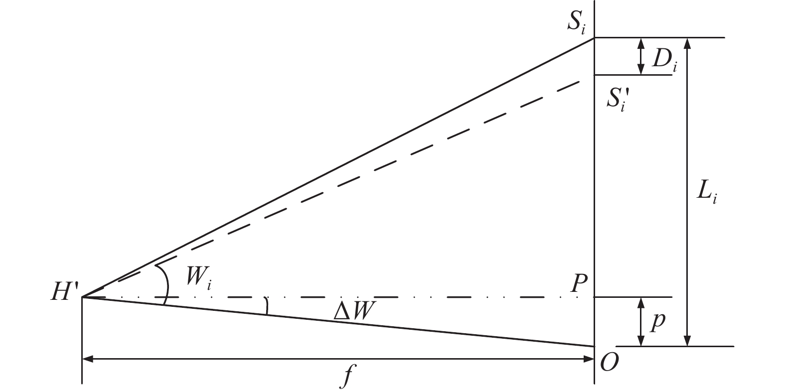
精密测角算法直观简洁,易于实现且精度较高,是实验室内标定测绘相机内方位元素采用的一种经典算法,其实质就是根据像点坐标数据和对应的入射光线角度数据,寻找一种主点、主距以及畸变系数的计算方法,使得相机的光学畸变符合一定的约束条件。
基于测角法的内方位元素和畸变测试原理如图1所示。图1中,
$ {H}{{'}} $ 为被测相机物镜的后节点,O为像面中心,P为像面主点位置, f为被测相机主距,$ {S}_{i} $ 为被测点,$ {S}_{i}{{'}} $ 为被测点的理想位置,$ {L}_{i} $ 为$ {S}_{i} $ 距像面中心O点的距离,$ {W}_{i} $ 为对应被测点的偏角,角度$ \Delta W $ 是主点和像面中心偏差所成的角度[11-12]。
图 1 一维内方位元素和畸变测量原理
Figure 1. Measurement principle of one dimensional interior orientation element and distortion
采用精密测角法测试时将光学镜头置于精密转台上,镜头焦面处放置模拟靶标,测量时将标定过的网格板刻划面精确地安置在镜头焦面上,并且使其刻线中心与镜头光轴重合。测试时,转动高精度二维转台,获取模拟靶标上不同刻线位置,记录转台角度值,根据约束条件即可求解镜头畸变。常用的约束条件包括平均值法、谢尔兴算法、畸变平方和最小算法等[13],其中全视场畸变平方和最小约束方法较为常用,采用该约束条件时,可得畸变、主距的计算公式如下:
$$ {D}_{i}={L}_{i}-f\;{\tan}\;{\omega }_{i}+p\;{{\tan}}^{2}\;{\omega }_{i} $$ (1) $$ f=\frac{\left(\displaystyle\sum {L}_{i}{\;{\tan}}^{2}{\omega }_{i}\cdot \displaystyle\sum {\;{\tan}}^{3}{\omega }_{i}\right)-\left(\displaystyle\sum {L}_{i}\;{\tan}{\omega }_{i}\cdot \displaystyle\sum {\;{\tan}}^{4}{\omega }_{i}\right)}{\left(\displaystyle\sum {\;{\tan}}^{3}{\omega }_{i}\right)^{2}-\left(\displaystyle\sum {\;{\tan}}^{2}{\omega }_{i}\cdot \displaystyle\sum {\;{\tan}}^{4}{\omega }_{i}\right)} $$ (2) 根据精确标定的网格板不同刻线对应的像高Li和相机旋转的角度Wi,利用上述公式即可求出对应相机的主距以及对应各点的畸变值Di。
精密测角算法的标定精度与转台精度密切相关。国内外各个研究机构进行遥感相机畸变测试的基本原理均基于精密测角法,目前国际主流的测量水平可满足1∶10000比例尺航天测绘相机的研制需求。
-
传统测角法是通过旋转转台获得镜头不同视场的像高及其对应的角度,基于干涉原理的大口径长焦距光学系统几何畸变标定技术在传统测角法基础上进行了改进,提出了利用激光跟踪仪和特制靶球测试各视场像点像高的技术路径,在测量空间坐标系内,将激光跟踪仪靶球置于像点处,当靶球球心与干涉仪焦点位置重合时,可以形成干涉自准条纹。利用该原理把靶球精密定位在像点处,再使用激光跟踪仪测试像点坐标,从而得到像高数据。测试示意图如图2所示。

图 2 垂直装调镜头实验室几何畸变标定示意图
Figure 2. Schematic diagram of geometric distortion calibration of vertically mounted lens
整套测试系统包括激光跟踪仪、特制靶球、4D干涉仪、相机镜头、高精度测角系统和平面反射镜。相机镜头几何畸变实验室测试时,步骤如下:
(1) 首先利用经纬仪将相机的光轴和平面反射镜的法线调整平行并与大地调垂直;
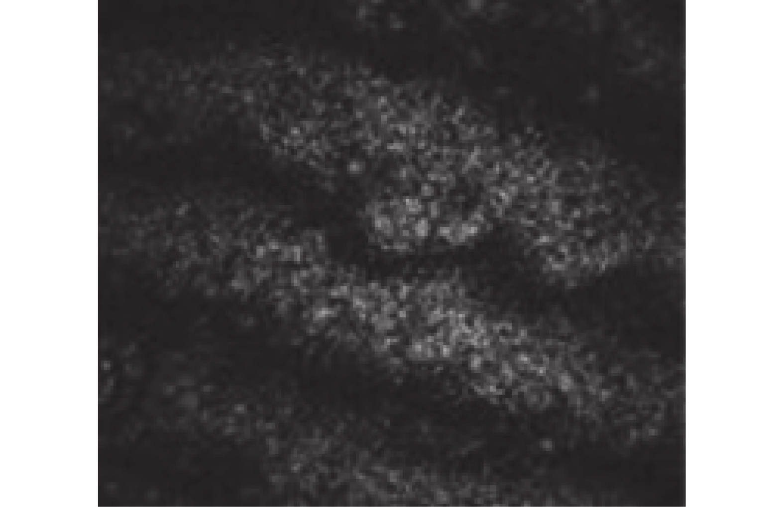
(2) 用4D干涉仪对镜头中心视场波前进行测试,光路调整完成后,将激光跟踪仪靶球放置于干涉仪的猫眼位置。跟踪仪靶球由抛光面和内部反射棱镜两部分组成,调整靶球位置,使得4D干涉仪激光光束投射到靶球的高抛光面,如图3所示。经过反射所成图像为图4所示的竖直条纹,此时靶球的中心位置即为镜头的焦面位置;

图 3 干涉仪与激光跟踪仪靶球干涉测试示意图
Figure 3. Schematic diagram of interferometer and laser tracker target ball test
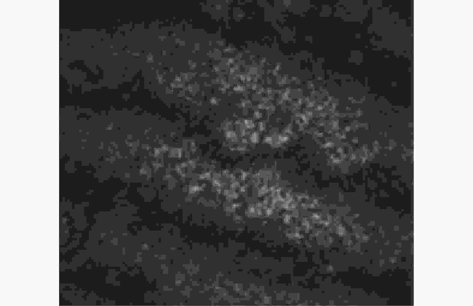
图 4 猫眼位置干涉条纹示意图
Figure 4. Schematic diagram of cat's eye position interference fringes
(3) 利用激光跟踪仪瞄准靶球的反射棱镜,得到靶球中心位置的三维坐标
$ {Z}_{i} $ ,从而确立了镜头畸变测试的主点坐标,将该位置作为测试初始点,进行后续测试;(4) 旋转平面反射镜,利用高精度测角系统测试平面反射镜的旋转角度
$ {\omega }_{i} $ ;(5) 调整4D干涉仪,搭建相机镜头不同视场角的波前测试光路,光路调整完成后,将靶球放置于干涉仪的猫眼位置,调整靶球位置,使得4D干涉仪所成图像为竖直条纹,此时靶球的位置即为镜头不同视场角的焦面位置。利用激光跟踪仪确定此时靶球的三维坐标
$ {Z}_{i} $ ,即可得到镜头在特定视场角条件下的实际成像位置$ {L}_{i} $ 。将
$ {{L}}_{{i}} $ 和$ {\omega }_{i} $ 代入公式(1)和(2),即可求出光学系统的主距以及对应各点的畸变值Di。该技术路径的畸变测试方法可同时满足各种类型光学镜头的畸变测试需求,当光学镜头采用传统方式装调时,镜头光轴处于水平状态,该状态下测试示意图如图5所示,测试步骤同上。

图 5 基于激光干涉原理的光学镜头实验室几何畸变标定示意图
Figure 5. Schematic diagram of optical lens distortion calibration based on laser interference principle
-
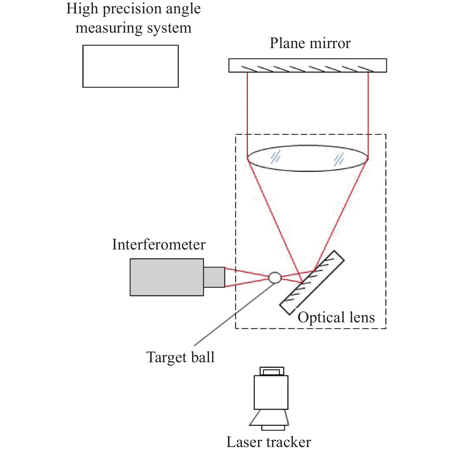
为提升角度的测试精度,文中利用多齿分度台和HR型光电自准直仪相结合搭建了高精度测角系统,如图6所示。在多齿分度台上架设光电自准直仪,使得光电自准直仪发射的激光通过平面反射镜后又返回,实现平面反射镜的角度测试。

图 6 高精度测角系统示意图
Figure 6. Schematic diagram of high-precision angle measuring system
为获取不同视场的像高,需要转动平面反射镜,以平面反射镜角度旋转间隔0.1°为例,在视主点位置时,调整多齿分度台和光电自准直仪的位置,使得光电自准直仪发出的光经过平面反射镜自准直返回,将光电自准直仪角度清零,设为初始值
$ {\omega }_{0} $ 。当进行下一个视场测试时,将平面反射镜沿光轴方向旋转0.1°,再将多齿分度台反向旋转0.1°,记录此时光电自准直仪上的角度$ {{\omega }_{1}}{{'}} $ ,则平面反射镜转过的角度$ {\omega }_{1}= 0.{1}^{\circ }+({{\omega }_{1}}{{'}}-{\omega }_{0}) $ 。由于多齿分度台的测角精度为±0.1″,HR型光电自准直仪小范围内的测角精度为±0.01″,因此高精度测角系统的组合测角误差为±0.1″,远远高于转台的测角精度。 -
利用传统的测角法和基于干涉原理的畸变测试方法对焦距2 000 mm,视场角2.8°的光学镜头进行了比对实验,比对结果如表1所示。
由标定结果可知,基于干涉原理的实验室畸变标定方法的测试结果与传统测角法的测试结果吻合度很高,两者的最大相对畸变分别为:
$ {D}_{{\rm{max}}} $ =1.48% (基于干涉原理的方法)$ {D{{'}}}_{{\rm{max}}} $ =1.49% (传统测角法),由此可见该方法能够满足遥感相机的研制要求且适用范围更广。 -
用上述的测试方法对被测相机进行了实际测试。被测相机焦距为8 m,视场角
$ 2\omega \geqslant 2.{2}^{\circ } $ ,主镜通光口径为800 mm。测试时全视场共取21个测试点,进行了三次有效测试,经过数据处理得到线阵方向畸变如表2所示,其中最大相对畸变值为:表 1 两种方法标定结果比对
Table 1. Comparison of calibration results of two methods
Traditional measurement Improvement measurement Image height/μm Distortion/μm Image height/μm Distortion/μm 776 −717.6 808 −723.9 7456 −418.4 7430 −424.6 14624 −299.1 14608 −301.1 21870 −153.2 21860 −161.3 29208 −76.4 29258 −79.9 36180 −53.3 36166 −45.6 43366 −13.5 43390 −9.9 49226 0 49280 0 55988 −21.1 56022 −31.2 63148 −56.2 63146 −54.2 70278 −87.0 70336 −84 77206 −171.8 77216 −180.6 84314 −320.9 84358 −311.2 91284 −426.3 91248 −433.1 101426 −727.5 101470 −731.4 $$ {D_{{\rm{max}}}= \frac{1\;809.2}{255\;889.2-129\;037.3}}=1.43 \text{%}$$ 如图7所示,通过对该相机光学系统模型的畸变网格数据可知,该相机线阵方向最大相对畸变设计值为1.5%。经过对比可以看出,文中提出的测试方法取得的测试结果与理论设计值吻合较好。三次重复测试,各采样点畸变测试的均方根小于3 μm,说明测试过程中随机误差较小,测试精度高。
表 2 三次畸变标定结果
Table 2. Cubic distortion calibration results
The first time The second time The third time RMS DIST/μm Image height/μm Distortion/μm Image height/μm Distortion/μm Image height/μm Distortion/μm 2158.1 1812.8 2154.6 1817.8 2156.8 1817.3 2.8 14887.6 1338.5 14885.5 1335.5 14886.2 1335.3 1.8 27508.6 937.6 27509.3 936.6 27508.9 937.5 0.6 40187.0 643.8 40189.1 644.8 48189.1 643.1 0.9 52900.4 372.3 52903.2 374.3 52901.1 376.2 2.1 65581.6 232.8 65578.1 227.8 65578.8 230.4 2.5 78271.2 85.9 78273.3 90.9 78269.3 89.2 2.5 90940.5 66.4 90937.7 65.4 90946.6 66.7 0.7 103671.4 30.8 103670.0 31.8 103684.7 32.7 1.0 116334.4 19.0 116335.1 14.0 116332.8 19.2 2.9 129037.3 0.0 129038.7 −1.0 129034.5 0 0.6 141724.1 4.3 141725.5 9.3 141724.9 8.3 2.6 154356.3 36.6 154356.3 32.6 154353.5 35.2 2.0 167048.7 68.1 167051.5 64.1 167052.0 65.0 2.1 179721.5 87.9 179721.5 87.9 179721.2 86.5 0.8 192423.0 258.8 192419.5 257.8 192426.3 258.2 0.5 205118.9 419.2 205119.6 416.2 205119.0 419.5 1.8 217805.0 681.9 217807.8 686.9 217819.0 683.9 2.5 230508.6 956.4 230505.8 952.4 230506.5 955.1 2.0 243236.7 1350.7 243233.9 1355.7 243210.1 1354.9 2.7 255889.2 1809.2 255892.0 1806.2 255903.2 1810.8 2.3 
图 7 相机光学系统模型畸变网格数据
Figure 7. Distortion grid data of camera optical system model
-
(1)主点测试误差
主点的测试精度主要取决于靶球的中心位置,靶球中心位置的获取受以下因素影响:干涉仪测试误差,干涉仪的测试精度优于0.1λ,因此可以忽略不计;激光跟踪仪测距精度16 μm;经纬仪自准直测角误差0.5″,测试中两次使用经纬仪,因此测角误差为0.7″。综上所述,主点测试误差为17 μm。
(2)主距测试误差
1) 主距的测量精度与畸变算法精度有关,基于测角法的主距误差计算公式为:
$$ {\delta }_{f}=\sqrt{\left(\frac{1}{\displaystyle\sum {\;{\tan}}^{2}{\omega }_{i}}{\delta }_{L}^{2}\right)^{2}+\frac{\displaystyle\sum {L}_{i}^{2}{{{\rm{sec}}}}^{4}{\omega }_{i}}{(\displaystyle\sum {\;{\tan}}^{2}{\omega }_{i}{)}^{2}}{\delta }_{\omega }^{2}} $$ (3) 式中:
$ {\delta }_{L} $ 为$ {L}_{i} $ 的测试误差,取决于靶标像位移计算精度;$ {\delta }_{\omega } $ 为角度$ {\omega }_{i} $ 的测试误差。2) 靶标像位移靠激光跟踪仪测量获取,激光跟踪仪测距精度为16 μm,即
$ {\delta }_{L} $ 精度为16 μm;3) 测角误差:测角误差包括光电自准直仪测角误差和多齿分度台测角误差。光电自准直仪测角误差为0.02″,多齿分度台经过高精度标定和校准测角误差可以达到0.1″,因此测角误差为0.11″。
综上所述,主距测试时质心计算误差优于16 μm,测角误差为0.11″,间隔0.5°进行测试采样,则相机主距f(8000 mm)的单轮测试误差
$ {\delta }_{f}=494.59 \;\text{μ} {\rm{m}} $ 。(3)畸变测试误差
基于测角法的畸变测试误差
$ {\delta }_{D} $ 主要包括[8-9]:1) 角度测试误差
$ {\delta }_{\omega } $ ;2) 像高测量误差
$ {\delta }_{L} $ ;3) 主点位置测量误差
$ {\delta }_{P} $ ;4) 主距测量误差
$ {\delta }_{f} $ ;5) 测试环境的影响:在测试中,要对温度、震动、气流等环境因素进行控制,尽量选择隔振地基、并且对测试环境严格控温、控气流扰动等,尽量减小或避免环境因素的影响;
6)测量间隔:在等精度条件下,测试间隔即镜头有效视场的测试点数对结果也有影响,测试间隔越小测试精度越高,测试间隔过大会对测试误差有较大影响。
畸变测试误差的表达式为:
$$ {\delta }_{D}^{2} = {\sum \left(\frac{\partial D}{\partial L}\right)}^{2}{\delta }_{L}^{2} + {\sum \left(\frac{\partial D}{\partial \omega }\right)}^{2}{\delta }_{\omega }^{2}+{\sum \left(\frac{\partial D}{\partial f}\right)}^{2}{\delta }_{f}^{2} + {\sum \left(\frac{\partial D}{\partial p}\right)}^{2}{\delta }_{p}^{2} $$ (4) 式中:
${\delta }_{f}=\sqrt{\left(\dfrac{1}{\sum {\;{\tan}}^{2}{\omega }_{i}}{\delta }_{L}^{2}\right)^{2}+\dfrac{\displaystyle\sum {L}_{i}^{2}{{{\rm{sec}}}}^{4}{\omega }_{i}}{({\;{\tan}}^{2}{\omega }_{i}{)}^{2}}{\delta }_{\omega }^{2}}$ ;$\left(\dfrac{\partial D}{\partial \omega }\right)^{2}= (-f{{{\rm{sec}}}}^{2}{\omega }_{i}-2 p{\tan}{\omega }_{i}{{{\rm{sec}}}}^{2}{\omega }_{i}{)}^{2}$ ;$\left(\dfrac{\partial D}{\partial p}\right)^{2}={{\tan}}^{4}{\omega }_{i}$ ;$\left(\dfrac{\partial D}{\partial L}\right)^{2}=1$ ;$\left(\dfrac{\partial D}{\partial f}\right)^{2}={\mathit{{\rm{tan}}}}^{2}{\omega }_{i}$ 。文中方法中高精度测角系统的测角误差
$ {\delta }_{\omega } $ 为±0.1″,像高$ {L}_{i} $ 由激光跟踪仪测试得到,激光跟踪仪测距误差为16 μm,代入公式(4),再根据相机的参数和测试间隔,经过计算可得,该方法对相机畸变的测试精度小于20 μm。 -
文中介绍了一种航天大口径长焦距光学系统畸变测试方法,在传统测角法的基础上,应用干涉测量原理测试镜头在不同视场的像高,用高精度测角系统可得到镜头不同视场像高对应的视场角,进而得到光学系统的畸变。该方法摒弃了传统测角法需要的高精度二维转台,能够同时满足各种类型光学遥感系统的畸变测试需求,操作简单,易于实现。文中分别用该方法对传统光学镜头和采用竖直装调的大口径高分辨率光学镜头进行了实验室畸变标定,结果与设计值吻合,为空间高分辨率光学遥感器的研制与测试提供参考。
Calibration technique of geometric distortion for space high resolution optical system
-
摘要: 遥感相机光学系统畸变系数作为影响相机在轨成像质量的关键因素,其检测精度一直以来都是遥感相机研制过程中的核心环节。传统的测角法主要依靠高精度二维转台,实现了光学系统视场角与像高之间的精准对应,该方法对测试设备和测试环境要求苛刻。随着相机焦距、口径和体积的增大,对于转台设备的尺寸与测量精度也日渐提升,单纯依靠提升测试设备性能无法满足后续各类高性能遥感相机的研制需求,尤其对于垂直装调类超大口径空间高分辨率光学系统,该方法不可行。在传统精密测角法的基础上,提出一种基于干涉原理的空间高分辨率光学系统几何畸变标定技术,相比于传统的精密测角法,该方法在同等测试精度的基础上,具备更广泛的适用性,其不再受限于测试设备的尺寸与精度限制,可同时满足各种类型遥感相机的畸变测试需求。文中详细介绍了该畸变测试方的基本原理、测试方法与误差链路,并对该畸变测试方法进行了应用验证,将结果与传统畸变测试方法进行对照,表明该方法的测试精度满足遥感相机的研制要求且适用范围更广,对航天长焦距大口径遥感相机研制及畸变测试有参考借鉴意义。Abstract:
As an important internal parameter of the camera, the measurement accuracy of distortion directly affects the image processing accuracy and the geometric positioning accuracy of the camera on orbit. The traditional high-precision laboratory calibration method relying on three-axis turntable has strict requirements for test equipment and test environment. With the increase of camera focus, aperture and volume, this method has increasingly high requirements for equipment and site. The idea of achieving high-precision geometric distortion calibration simply by improving the volume and accuracy of equipment is not applicable. On the basis of the traditional precision angle measurement method, this paper proposes a geometric distortion calibration technology of large aperture and long focal length optical system based on the interference principle. Compared with the traditional precision angle measurement method, this method does not require a high-precision experimental turntable, has good robustness and high accuracy. This paper introduces the basic principle, test method and error link of the distortion test method. The test results of this method are compared with the traditional distortion test method, which shows that the test accuracy of this method meets the requirements of remote sensing camera development and has a wider application range. It can be used for reference for the distortion test of aerospace long focal length and large aperture remote sensing camera. Objective As an important internal parameter of the camera, the measurement accuracy of distortion directly affects the image processing accuracy and the geometric positioning accuracy of the camera on orbit. At present, the distortion test methods for optical cameras are generally divided into three categories, the high-resolution spaceflight remote sensing camera is more suitable for the test method based on the precision angle measurement theory. However, the precision angle measurement method has strict requirements for the test equipment and the test environment. With the increase of the focal length, aperture and volume of the spatial high-resolution optical system, higher requirements are also put forward for the size and test accuracy of the turntable. It is difficult to realize in engineering and cannot meet the development requirements of various types of space high-resolution remote sensing cameras. Meanwhile, for the space high-resolution optical systems with ultra-large aperture and ultra-long focal length, in order to reduce the influence of gravity in the process of alignment, the vertical method is usually used for alignment. The visual axis of the lens is always perpendicular to the earth in this case, and it is impossible to use the traditional precision angle measurement method to calibrate the distortion of the optical lens in the laboratory. In order to solve this problem, a geometric distortion calibration technology of large aperture and long focal length optical system based on the interference principle is proposed. Methods The whole test system includes laser tracker, special target ball, 4D interferometer, a measured lens, high-precision angle measuring system and plane reflector (Fig.2, Fig.5). In the measurement space coordinate system, the target ball of the laser tracker is placed at the image point (Fig.3). When the center of the target ball coincides with the focus position of the interferometer, the interference self-collimation fringe can be formed (Fig.4). When the target ball is precisely positioned at the image point, the laser tracker can be used to test the image point coordinates to obtain the image height data. The field angle corresponding to the image height of the lens can be obtained by using the high-precision angle measurement system (Fig.6), and the lens distortion value can be calculated by the image height and its corresponding field angle. Results and Discussions Comparative experiments were carried out on optical lens with a focal length of 2 000 mm and a field angle of 2.8° using the traditional angle measurement method and the distortion measurement method based on the interference principle. The calibration results show that the results of the two test methods are highly consistent, and the maximum relative distortion of the two methods are 1.48% and 1.49% (Tab.1). This shows that the method based on interference principle can meet the development requirements of remote sensing camera. A long focal length and large aperture optical lens is tested with the new method. During the test, a total of 21 test points were taken from the full field of view, and three effective tests were conducted (Tab.1). The root-mean-square distortion of the three tests is less than 3 microns, and the maximum relative distortion value is 1.43%. The maximum relative distortion design value of the lens linear array direction is 1.5% (Fig.7), and the test results are in good agreement with the theoretical design value. Conclusions Based on the traditional angle measurement method, a distortion measurement method for aerospace large aperture and long focal length optical system is proposed. This method can meet the distortion test requirements of various types of optical systems. It is used to calibrate the distortion of the traditional optical lens and the large-aperture high-resolution optical lens with vertical adjustment in the laboratory. The results are consistent with the design values, which provides a reference for the development and test of space high-resolution optical remote sensor. -
图 1 一维内方位元素和畸变测量原理
Figure 1. Measurement principle of one dimensional interior orientation element and distortion
图 2 垂直装调镜头实验室几何畸变标定示意图
Figure 2. Schematic diagram of geometric distortion calibration of vertically mounted lens
图 3 干涉仪与激光跟踪仪靶球干涉测试示意图
Figure 3. Schematic diagram of interferometer and laser tracker target ball test
图 4 猫眼位置干涉条纹示意图
Figure 4. Schematic diagram of cat's eye position interference fringes
图 5 基于激光干涉原理的光学镜头实验室几何畸变标定示意图
Figure 5. Schematic diagram of optical lens distortion calibration based on laser interference principle
表 1 两种方法标定结果比对
Table 1. Comparison of calibration results of two methods
Traditional measurement Improvement measurement Image height/μm Distortion/μm Image height/μm Distortion/μm 776 −717.6 808 −723.9 7456 −418.4 7430 −424.6 14624 −299.1 14608 −301.1 21870 −153.2 21860 −161.3 29208 −76.4 29258 −79.9 36180 −53.3 36166 −45.6 43366 −13.5 43390 −9.9 49226 0 49280 0 55988 −21.1 56022 −31.2 63148 −56.2 63146 −54.2 70278 −87.0 70336 −84 77206 −171.8 77216 −180.6 84314 −320.9 84358 −311.2 91284 −426.3 91248 −433.1 101426 −727.5 101470 −731.4  下载: 导出CSV
表 2 三次畸变标定结果
Table 2. Cubic distortion calibration results
The first time The second time The third time RMS DIST/μm Image height/μm Distortion/μm Image height/μm Distortion/μm Image height/μm Distortion/μm 2158.1 1812.8 2154.6 1817.8 2156.8 1817.3 2.8 14887.6 1338.5 14885.5 1335.5 14886.2 1335.3 1.8 27508.6 937.6 27509.3 936.6 27508.9 937.5 0.6 40187.0 643.8 40189.1 644.8 48189.1 643.1 0.9 52900.4 372.3 52903.2 374.3 52901.1 376.2 2.1 65581.6 232.8 65578.1 227.8 65578.8 230.4 2.5 78271.2 85.9 78273.3 90.9 78269.3 89.2 2.5 90940.5 66.4 90937.7 65.4 90946.6 66.7 0.7 103671.4 30.8 103670.0 31.8 103684.7 32.7 1.0 116334.4 19.0 116335.1 14.0 116332.8 19.2 2.9 129037.3 0.0 129038.7 −1.0 129034.5 0 0.6 141724.1 4.3 141725.5 9.3 141724.9 8.3 2.6 154356.3 36.6 154356.3 32.6 154353.5 35.2 2.0 167048.7 68.1 167051.5 64.1 167052.0 65.0 2.1 179721.5 87.9 179721.5 87.9 179721.2 86.5 0.8 192423.0 258.8 192419.5 257.8 192426.3 258.2 0.5 205118.9 419.2 205119.6 416.2 205119.0 419.5 1.8 217805.0 681.9 217807.8 686.9 217819.0 683.9 2.5 230508.6 956.4 230505.8 952.4 230506.5 955.1 2.0 243236.7 1350.7 243233.9 1355.7 243210.1 1354.9 2.7 255889.2 1809.2 255892.0 1806.2 255903.2 1810.8 2.3
下载: 导出CSV
-
[1] Wang Qiaoping, Qi Wenwen, Tan Wei. Maneuvering imaging quality of space TDI push scan optical remote sensor [J]. Infrared and Laser Engineering, 2022, 51(10): 20220094. (in Chinese) [2] Qin Zichang, Ren Chengming, Qi Yunsheng, et al. Low error-sensitive design of small-sized high-resolution space camera optical system [J]. Infrared and Laser Engineering, 2022, 51(10): 20220365. (in Chinese) [3] Jiang Xiwen, Zhao Jinyu, Lu Tianyu, et al. Design and alignment of large-aperture prime focus optical system [J]. Optics and Precision Engineering, 2022, 30(23): 2987-2994. (in Chinese) doi: 10.37188/OPE.20223023.2987 [4] Lu Bo, Feng Rui, Kou Wei, et al. Optical system design and stray light suppression of catadioptric space camera [J]. Chinese Optics, 2020, 13(4): 822-831. (in Chinese) doi: 10.37188/CO.2019-0036 [5] Fan Wenqiang, Wang Zhichen, Chen Baogang, et al. Review of the active control technology of large aperture ground telescopes with segmented mirrors [J]. Chinese Optics, 2020, 13(6): 1194-1208. (in Chinese) doi: 10.37188/CO.2020-0032 [6] Li Chongyang, Zhang Zhifei, Lv Chong, et al. System integration and test of GF-7 bi-linear array stereo mapping sensing camera [J]. Infrared and Laser Engineering, 2021, 50(1): 20200143. (in Chinese) doi: 10.3788/IRLA20200143 [7] Zhang Jiyou, Wang Dongjie, Ma Lina. The self-calibration technology of camera intrinsic parameters calibration methods [J]. Imaging Science and Photochemistry, 2016, 34(1): 15-22. (in Chinese) [8] Cheng Qiang, Hu Haixiang, Li Longxiang, et al. Distortion analysis and focal length testing of off-axis optical system [J]. Optics and Precision Engineering, 2022, 30(22): 2839-2846. (in Chinese) doi: 10.37188/OPE.20223022.2839 [9] Li Chongyang, Dong Xin, Yue Liqing, et al. Testing method of distortion for space remote sensing camera with large field of view [J]. Infrared and Laser Engineering, 2018, 47(11): 0117003. (in Chinese) [10] Yang Shourui, Duan Wanying, Ai Wenyu, et al. Light field camera modeling and distortion correction improvement method [J]. Infrared and Laser Engineering, 2023, 52(1): 20220326. (in Chinese) doi: 10.3788/IRLA20220326 [11] Fu Ruimin, Zhang Yuanming, Zhang Jiyou. Study on geometric measurement methods for line-array stereo mapping camera [J]. Spacecraft Recovery & Remote Sensing, 2011, 32(6): 62-67. (in Chinese) [12] Liu Weiyi, Jia Jiqiang, Ding Yalin, et al. Measurement error impact on intrinsic parameters calibration in precise angle measurement method [J]. Infrared and Laser Engineering, 2009, 38(4): 705-706. (in Chinese) [13] Zhang Jiyou. Simulation of geometric measurement method for stereo mapping camera. [J]. Spacecraft Recovery & Remote Sensing, 2012, 33(3): 48-53. (in Chinese) -

 点击查看大图
计量
- 文章访问数: 211
- HTML全文浏览量: 36
- PDF下载量: 49
- 被引次数: 0


