


-
空间遥感技术是利用卫星搭载可见光、红外等传感器,收集地球表面和近地空间的电磁辐射数据,并将其转变为所需的信号或图像[1]。该技术广泛应用于军事侦察、摄影测绘、生态监测等领域。空间遥感相机是近年来的研究重点,其遥测感知能力是高效率获取地球信息的关键[2]。尤其是在卫星侦擦领域,需要空间遥感相机具备更宽的视场以及更高的分辨率,以此获得敌方军事部署以及其他信息。然而,受限于探测器像元尺寸和幅面大小,如何设计出兼备大视场和高分辨率成像的紧凑型遥感相机具有一定难度,也成为了国内外的研究热点。
在轨道高度一定的情况下,相机的视场越大,系统对地观测面积越大,扫描周期越短,可有效提高相机的广域搜索能力,高分辨率成像通常是采用大口径的同轴光学结构实现,然而大口径光学系统像差往往较大,进而限制了视场大小。若采用大口径离轴TMA结构来获得较宽的视场,则除了主镜外,第三镜也需设计大口径来接收宽视场的光线。与同轴结构相比,在相同的分辨率的情况下,扩大视场会使得离轴结构的体积增大。
传统的光学系统完成大视场搜索和高分辨成像任务是通过两单独系统交互信息后配合完成的,首先由大视场的系统对目标进行捕捉,将目标的空间位置信息传递至高分辨率、小视场的系统对目标进行连续观测,但两个单独的系统会使得整体结构变得十分笨重,在空间有限的遥感相机上不易采用。另外,传统的遥感卫星信息获取流程复杂、链路长,有效信息的获取难以满足分钟级甚至秒级的获取需求[3],随着通导遥一体化智能遥感卫星的方案提出,其基于通信、导航、遥感等多载荷的集成于一体化协同布局构建而成的一种多功能卫星平台,可快速提高空间信息获取、传输、处理和分发的能力[4]。珞珈三号01星采用该方案并利用相关软件平台,实现遥感数据的在轨实时处理,同时,其具备凝视成像、面阵推帧及面阵推扫三种成像模式,可根据不同的任务进行工作模式的切换,为遥感卫星获取的信息具备一定的时效性奠定了基础。
2015年,韩国的Kompsat-3A卫星[5]中遥感相机采用了Korsch型光学结构,其焦距为8.6 m,口径为0.8 m,幅宽为12 km,可获得0.55 m分辨率的可见光图像及5.5 m分辨率的红外图像。2015年,我国的“吉林一号”光学A星搭载的高分辨率遥感相机采用同轴三反光学结构[6],其焦距为7.98 m,口径为0.6 m,幅宽为11.6 km,但其全色分辨率相对较低,仅优于0.72 m。2018年,赵宇宸设计了一款遥感光学载荷[7],该系统的焦距为2.5 m,口径为0.4 m,视场为0.6°×0.6°,其采用同轴三反光学结构并加入偏视场来消除二次遮拦,利用两平面反射镜折叠光路,然后利用两块分色镜将后端分为可见、近红外和中波红外通道,可分别获得0.8、2.5、6.8 m地面分辨率的可见光、近红外及中波红外图像。2019年,孙永雪[8]等人采用离轴三反结构设计了一款遥感相机,其焦距为0.5 m,口径为130 mm,视场为5°×2°,采用共光路和分视场方式实现了可见光和微光探测器同时成像,但其可见光地面分辨率较低,仅为3 m。2022年,李庆林[9]等人采用离轴三反结构设计了一款遥感相机,其焦距为2.21 m,视场角为8.8°,口径为0.45 m,全色分辨率为2 m。
由于目前大部分卫星所搭载的遥感相机不能同时兼备大视场探测和高分辨率识别,针对该问题,文中提出了一种具备大视场搜索和高分辨率成像的光学系统。高分辨率成像模块采用同轴折反式结构,可提供0.45 m分辨率的可见光图像和3.2 m分辨率的中波红外波段图像。大视场搜索模块采用离轴四反结构,两模块通过共用主反射镜,可有效地减小系统的体积和质量,并能够同时满足大视场广域搜索和高分辨成像的需求。
-
空间遥感相机的地面分辨率GSD是由卫星轨道高度H、探测器像元尺寸p及光学系统的焦距$ f' $共同决定的,其关系为[10]:
$$ {G_{SD}} = \frac{{H \cdot p}}{{f'}} $$ (1) 当H为500 km时,要求可见光成像模块、中波红外成像模块及可见光搜索模块的地面分辨率GSD分别优于0.45、3.2、8 m。另外,为了实现遥感相机的小型化及轻量化,光学系统的包络尺寸需小于0.9 m×0.9 m×1.2 m,同时光学系统的质量需小于200 kg。
该设计中,可见光搜索模块选用的探测器的像元尺寸为15 μm×15 μm,像元阵列为4096×4096;可见光成像模块采用探测器的像元尺寸为3.76 μm×3.76 μm,像元阵列为6252×4176;中波红外成像模块采用像元阵列为384×288的红外焦平面探测器,像元尺寸为25 μm×25 μm。
由公式(1)可求得可见光成像模块、中波红外成像模块及可见光搜索模块的焦距至少分别为4178 mm、3900 mm和937.5 mm。根据焦距、视场角和像高的三者关系,制定该系统技术指标如表1所示。
表 1 技术指标要求
Table 1. Technical specification
Sequence number Technical index Visible-light imaging module Medium-wave-infrared imaging module Visible-light searching module 1 Wavelength/μm 0.45-0.9 3.7-4.8 0.45-0.9 2 Entrance pupil diameter/mm 800 800 130 3 Full field of view/(°) 0.4 0.4 10 (linear) 4 Effective focal length/mm 4200 4000 945 5 Ground resolution/m ≤0.45 ≤3.2 ≤8 6 MTF/lp·mm–1 ≥0.2@133 ≥0.2@20 ≥0.2@33 -
遥感相机在环绕地球飞行过程中,其与地面目标之间存在相对运动,可通过摆扫式、推扫式和凝视三种成像方式来获取地面信息[11]。设计中,遥感相机的大视场搜索模块采用推扫成像,通过遥感相机和地表景物相对位置的变化进行扫描成像,高分辨成像模块采用凝视成像。遥感相机中的搜索模块采用推扫方式来实现大范围的广域搜索,发现目标并进行数据反馈后,通过调整卫星姿态,使系统光轴对准搜索区域中的目标进行可见光和中波红外波段高分辨凝视成像。
高分辨率成像模块采用同轴折反射式光学系统,搜索模块采用离轴反射式光学系统,各系统均共用一个大口径反射镜,两成像模块采用相同视场,可同时提取同一目标的可见光和中波红外波段的图像信息。设计时,优先对大视场搜索模块进行设计优化,达到设计指标后,固定主镜的各项参数并在此基础上设计可见光成像模块及中波红外成像模块。
-
可见光搜索模块的子午方向仅具有零视场,但在弧矢方向具有较大观察视场角(±5°)。 搜索模块采用离轴四反结构,设计时,大口径主镜的面型选择抛物面,通过施加适当的偏心及倾斜,初步确定M2和M3两反射镜的位置,并将孔径光阑设置在次镜 M2 处。入射光束首先通过共用的大口径主镜(M1)下半部反射,经过反射镜M2将光束再次反射到M1的上半部分,最后利用反射镜M3将光束成像在像面处。可见光搜索模块的结构图如图1所示。

图 1 可见光搜索模块结构图
Figure 1. Structure of visible light search module
由于离轴结构具有非旋转对称性,离轴物点在子午和弧矢方向的聚焦存在较大差异。Biconic Zernike自由曲面在x、y方向上具有不同的曲率和圆锥系数[12],适合大散光的校正,因此M2、M3反射镜的面型选择Biconic Zernike自由曲面面型,Biconic Zernike自由曲面由二次项、高次项和Zernike项三部分组成,其方程为:
$$ \begin{split} z = \frac{{{c_x}{x^2} + {c_y}{y^2}}}{{1 + \sqrt {1 - \left( {1 + {k_x}} \right)c_x^2{x^2} - (1 + {k_y})c_y^2{y^2}} }} + \\ \sum\nolimits_{i = 1}^{16} {{\alpha _i}} {x^i} + \sum\nolimits_{i = 1}^{16} {{\beta _i}} {y^i} + \sum\nolimits_{i = 1}^N {{A_i}} Z{}_i\left( {\rho ,\theta } \right) \\ \end{split} $$ (2) 式中:$ {c_x} $和$ {c_y} $为x和y方向的曲率;$ {k_x} $和$ {k_y} $为二次曲面系数;$ \alpha $和$ \;\beta $分别为x和y的非球面系数;$ {A_i} $为标准泽尼克多项式中第$ i $个系数;$\; \rho $为归一化的径向坐标,$ \theta $为角坐标。拟合后M2、M3自由曲面反射镜的面型如图2所示。
另外,为了避免光束遮拦,利用ZPL宏来约束各反射镜之间的相对位置,并对M2、M3反射镜的偏心及倾斜等参数进行优化,同时将像面倾斜一定角度来提升像质。经优化后,可见光搜索模块的焦距为945 mm,工作F数为4.0,弧矢方向全视场为10°,满足设计指标要求。图3为可见光搜索模块的调制传递函数(MTF)曲线。
对于可见光搜索模块,对应探测器的像元尺寸大小为15 μm×15 μm,可得出其奈奎斯特频率为 33 lp/mm。由图3可见,可见光搜索模块各视场的MTF在奈奎斯特频率33 lp/mm处均大于0.35,成像质量较好。

图 2 拟合后M2、M3自由曲面反射镜的面型。(a) M2反射镜; (b) M3反射镜
Figure 2. The surface shape of M2 and M3 free-form mirror after fitting. (a) Mirror M2; (b) Mirror M3

图 3 可见光搜索模块的MTF曲线
Figure 3. MTF curves of visible light search module
-
对于成像模块而言,其空间分辨率越高, 获取的图像信息就越丰富。在卫星的运行轨道高度确定的前提下,可通过增加系统焦距来提高卫星的地面分辨率,因此系统采用同轴两反的结构来适应长焦距,并加入折射镜组校正像差。设计时,首先固定主镜的各项参数,并在此基础上对可见光成像模块进行设计优化,达到设计指标后再设计中波红外成像模块。
-
同轴两反光学系统的初始结构可由像差理论中相关公式计算得出[13]。对初始结构进行优化时,将孔径光阑置于主镜上,以此减小主镜尺寸和系统成本。通过控制次镜的尺寸,确保系统具有较小的遮拦比,同时采用三片球面透镜来校正系统的残余像差。优化后,系统的F数为5.25,遮拦比为0.226,主镜的面型为抛物面,次镜的面型为双曲面。系统总长为800 mm,焦距为4200 mm,筒长焦距比为1/5.25。考虑到搜索模块M2反射镜的存在会引起同轴系统的遮拦,设置遮拦后,可见光成像模块的光学系统结构如图4所示。

图 4 可见光成像模块结构图
Figure 4. Structure of visible light imaging modul
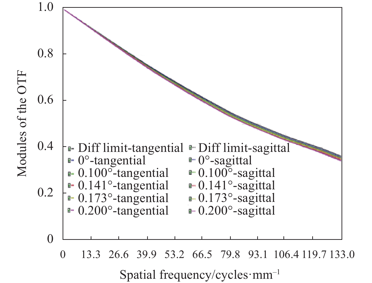
对于可见光成像模块,对应探测器的像元尺寸大小为3.76 μm×3.76 μm。根据奈奎斯特采样定律,可得出奈奎斯特频率为 133 lp/mm。图5和6分别为可见光成像模块的点列图和MTF曲线。
虽然反射镜 M2 的存在会造成一定遮拦,但遮拦面积较小且不在光轴中心,对系统成像 质量影响较小。由图5可见,可见光成像模块(加入遮拦后)的各个视场的弥散斑均收敛于艾里斑以内,且最大的RMS半径仅为1.433 μm。如图6所示,可见光成像模块的MTF曲线接近衍射极限,且在奈奎斯特频率处,各视场的MTF均大于0.3。

图 5 可见光成像模块的点列图
Figure 5. Spot diagram of visible light imaging module

图 6 可见光成像模块的MTF曲线
Figure 6. MTF curves of visible light imaging module
-
中波红外成像模块的结构如图7所示,其中反射至M2的光束将进入搜索系统。该模块与可见光成像模块共用大口径主镜,次镜材料选用中波红外波段透过率较高的ZnSe,其材料杂质少,吸收系数小,可以降低对中波探测能量的损耗[14]。次镜的后表面镀全介质膜,可实现在次镜位置处反射可见光波段,同时透射中波红外波段。为了使系统具有较高的探测灵敏度和响应度,需将制冷型探测器的光阑置于探测器的冷屏处,以获得100%的冷光阑效率[15]。

图 7 中波红外成像模块结构图
Figure 7. Structure of medium wave infrared imaging module
优化时,采用三次成像的结构来减小后端透镜的尺寸,将系统的出瞳位置放置在冷光阑处,并利用六片Ge镜和三片Si镜来校正大口径系统带来的各种像差。利用两块平面反射镜将光路进行折叠。优化后,中波红外成像模块焦距为4000 mm,F数为5.0。图8和图9分别为中波红外成像模块的MTF曲线和点列图。

图 8 中波红外成像模块的MTF曲线
Figure 8. MTF curves of medium wave infrared imaging module
对于中波红外成像模块,对应探测器的像元尺寸大小为25 μm×25 μm,可求得其奈奎斯特频率为20 lp/mm。由图8可以看出,该模块的各个视场的弥散斑均收敛于艾里斑内。由图9可以看出,中波红外成像模块的MTF在20 lp/mm 均优于0.35,曲线平滑且贴近衍射极限,可见其具有良好的成像质量。

图 9 中波红外成像模块点列图
Figure 9. Spot diagram of medium wave infrared imaging module
-
整合后的大视场搜索与高分辨成像一体化光学系统整体如图10所示, 图11为主镜M1的光迹图。整合后的光学系统总长为 0.8 m,宽度为 0.8 m,高度为 1.1 m。
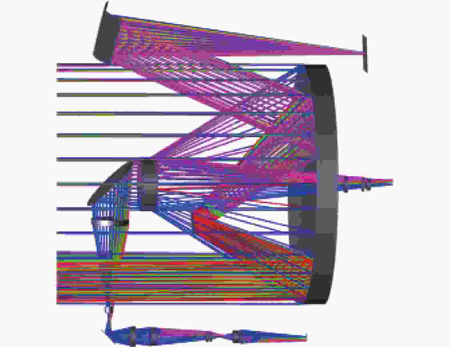
图 10 光学系统整体图
Figure 10. Optics system configuration

图 11 主镜M1的光迹图
Figure 11. Light trace of incident rays on M1
由图11 可以看出,系统的遮拦主要由可见光成像模块的次镜和大视场搜索模块中的 M2反射镜引起,其中次级的遮拦比为5.063%,M2反射镜遮拦面积仅占整个大口径主镜面积(除去次镜面积)的0.8%,同时两者的垂轴距离预留出20 mm的间距,为后续系统的机械结构留出一定余量。
整套光学系统的质量主要集中于高分辨成像模块中的大口径反射主镜M1和次镜,以及可见光搜索模块中的自由曲面反射镜M2和M3。反射镜材料采用SiC陶瓷材料,并根据实际加工经验,按照8∶1的径厚比给定各个反射镜的中心厚度,可估算出光学系统的整体质量约为140 kg。
该空间遥感相机的轨道高度为500 km,其中可见光和中波红外成像模块在0.4°的全视场范围内,分别实现对2.813 km×1.879 km和1.228 km×0.922 km的区域进行观测,其中可见光成像模块的地面分辨率优于0.45 m,中波红外成像模块的地面分辨率优于3.2 m。搜索模块在弧矢视场10°范围内将以8 m的地面分辨率完成33 km线宽的推扫成像。
该系统通过复用大口径主镜的形式将三个分离的模块整合至一个系统中,使得系统结构更为紧凑,且具有良好的像质,能够满足系统的大视场搜索和小视场多波段高分辨成像的需求。
-
公差分析为光机零件加工和组件装调提供精度控制参考值。经过公差分析,满足高分辨成像模块的加工公差及装调公差,分别如表2和表3所示。
表 2 元件的加工公差
Table 2. Machining tolerance of components
Item Parameter Fringes ±1.0 Thickness/mm ±0.02 Surface tilt/(″) ±0.5 Surface decenter/mm ±0.02 表 3 元件的装调公差
Table 3. Assembly and adjustment tolerance of components
Item Parameter Interval/m ±0.02 Element tilt/(″) ±0.5 Eccentric element/mm ±0.02 系统中,主次镜的 RMS 面型误差为 λ/50@633 nm,其他光学元件的RMS面型误差为 λ/15@633 nm,且主次镜的元件偏心倾斜为10″。采用“MTF 衍射平均值”模式为公差分析的评价标准,并利用蒙特卡洛法对 1000 组镜头数据进行分析,可见光成像模块及中波红外成像模块的公差分析结果分别如表4和表5所示。
表 4 可见光成像模块公差分析结果
Table 4. Tolerance analysis result of visible light image module
Title Result Traceable Monte Carlo generation number 1000 The name of the MTF value 0.367 The average MTF 0.285 MTF value of 98% lens >0.214 MTF value of 90% lens >0.240 MTF value of 80% lens >0.258 MTF value of 50% lens >0.288 MTF value of 20% lens >0.313 MTF value of 10% lens >0.323 MTF value of 2% lens >0.338 由表4和表5可以看出,在给定的公差范围内,可见光成像模块有98%的概率使其MTF在133 lp/mm处大于0.214,满足设计指标要求;当中波红外成像模块公差满足要求时,有98%的概率使得其MTF在20 lp/mm处大于0.201。
表 5 中波红外成像模块公差分析结果
Table 5. Tolerance analysis results of medium wave
Title Result Traceable Monte Carlo generation number 1000 The name of the MTF value 0.396 The average MTF 0.283 MTF value of 98% lens >0.201 MTF value of 90% lens >0.212 MTF value of 80% lens >0.245 MTF value of 50% lens >0.290 MTF value of 20% lens >0.341 MTF value of 10% lens >0.361 MTF value of 2% lens >0.385 -
自由曲面因其非旋转对称性,加工难度更大,故对其进行加工工程分析更重要。面型公差是指加工后的面型与理想面型的差异,面型公差会导致光学系统性能下降。因此,应对系统中的自由曲面进行面型公差分析以确定容许的误差范围。Zemax光学软件可对传统球面及非球面进行面型公差分析,但对于自由曲面的面型分析存在局限性。因此,文中采取随机统计法来对自由曲面进行面型公差分析[16]。
搜索模块的反射镜M2、M3为Biconic Zernike自由曲面,其面型方程已知,在自由曲面上均匀取任意多个点,根据方程可得任意点的矢高$ {z_{i,j}} $ 为:
$$ {z_{i,j}} = f\left( {{x_{i,j}},{y_{i,j}}} \right) $$ (3) 在公式(3)上加入一个随机变量$ \Delta {z_{i,j}} $,可表示加工过程中产生的面型误差,其任意点矢高变为:
$$ {z'_{i,j}} = {z_{i,j}} + \Delta {z_{i,j}} $$ (4) 其中:
$$ \Delta {z_{i,j}} = H{r_{and}} $$ (5) 式中:H为面型误差峰谷值;$ {r_{and}} $为0~1区间的随机数。
根据引入随机误差的自由曲面的数据点,重新拟合成新的自由曲面并输出自由曲面的各项参数,最后导入到Zemax中查看搜索模块的光学性能。
根据随机统计法,搜索模块的两个自由曲面的表面面型误差峰谷值H分别为0.25 μm和0.17 μm(搜索模块的系统主波长为0.587 μm)。图12为在对应H下的随机20组公差下的MTF数据。搜索模块的MTF在33 lp/mm处均大于0.2,可见自由曲面的面型精度公差分析合理。

图 12 样本数20组下两个自由曲面的公差分析。(a) H为0.25 μm下反射镜M2的MTF分布;(b) H为0.17 μm下反射镜M3的MTF分布
Figure 12. Tolerance analysis of two freeform surfaces under 20 sets of samples. (a) MTF distribution of mirror M2 with H of 0.25 μm; (b) MTF distribution of mirror M3 with H of 0.17 μm
-
文中根据给定的技术参数要求,设计了一种具备大视场搜索与高分辨成像的遥感相机光学系统。其中,大视场搜索模块与成像模块共用一个大口径反射镜,利用次镜分光的方式将成像模块分为可见光和中波红外两成像模块;并将搜索 模块与高分辨成像模块一体化设计,降低了系统的体积和质量。经公差分析,搜索模块和高分辨成像模块均可满足设计指标,且系统结构紧凑,利于系统实现小型化、轻量化,对于多模卫星光学载荷的设计具有一定的参考价值,同时在卫星遥感领域具有一定的应用前景。
Optical system design of common-aperture multimode remote sensing camera
-
摘要: 为了使遥感相机同时具备大视场搜索和多波段高分辨成像功能,提出了一种成像与搜索模块一体化的遥感相机光学系统。大视场搜索模块采用离轴四反结构,通过推扫的模式对目标区域进行扫描;小视场成像模块通过次镜分光,实现可见光和中波红外同时高分辨成像。各系统复用大口径主镜有效降低了遥感相机的体积和质量。当轨道高度为500 km时,该系统可实现以8 m的地面分辨率对33 km线宽的地面进行推扫搜索,确定目标后,通过调整卫星姿态,使可见光和中波红外成像模块分别以 0.45 m 和 3.2 m 的分辨率对地面目标进行高分辨凝视成像。公差分析结果表明,可见光成像模块、中波红外成像模块以及搜索模块各视场的调制传递函数(MTF)分别在其奈奎斯特频率处(133 lp/mm、20 lp/mm和33 lp/mm)均大于0.2。该系统能够满足实际加工和装调要求,为实现紧凑型空间光学系统的设计提供了一种可行性方案。Abstract:
Objective Scenery changes on the earth are utilized for space remote sensing cameras to perform imaging during flying around the earth. The larger field of view a space remote sensing camera has, the larger observation area on the earth the system will obtain. However, high-resolution imaging is usually achieved by using an optical system with large aperture, which will lead to more aberration. This will further limit the field of view of the system. At present, the remote sensing cameras equipped in most satellites cannot have both large-field-of-view detection and high-resolution recognition. Aiming at this problem, a compact space remote sensing camera with large-field-of-view search and multi-band high-resolution imaging is designed in this paper. Methods The integrated optical system with functions of large-field-of-view search and high-resolution imaging is shown (Fig.10). A primary mirror with large aperture is shared by the large-field-of-view search module and the high-resolution imaging module, to reduce the weight and overall size volume of the system. Cassegreen structure is adopted in the high-resolution imaging module, involving a visible-light imaging module and a mid-wave infrared imaging module, which are splitted by the secondary mirror. An off-axis four-mirror structure is adopted in the large-field-of-view search module. Two freeform mirrors with the Biconic-Zernike shape are used to correct the aberrations. Results and Discussions In this paper, an optical system for a compact space remote sensing camera with both large-field-of-view search and high-resolution imaging is proposed. The overall weight of the optical system is about 140 kg, and the overall volume is 0.8 m×0.8 m×1.1 m. The focal length of the large-field-of-view search module is 945 mm with field of view in the sagittal direction of 10°. The diameter of the entrance pupil is 130 mm and the working waveband is 0.45-0.9 μm. The optical structure is shown (Fig.1). The resolution of 4 096×4 096 for the detector is adopted with pixel size of 15 μm×15 μm. When the orbit height is 500 km, the system can search the ground with line width of 33 km and ground resolution of 8 m. The high-resolution imaging module is composed of a visible light imaging module and a mid-wave infrared (MWIR) imaging module. The focal length of the visible-light imaging module is 4 200 mm. The resolution of 6 252×4 176 for the detector is adopted with pixel size of 3.76 μm×3.76 μm. The MWIR imaging module has a focal length of 4 000 mm, a detector resolution of 384×288 and a pixel size of 25 μm×25 μm. A large-aperture primary mirror is shared by a visible-light module and a MWIR imaging module, with the same diameter of 800 mm. When the orbital height is 500 km, the visible-light and MWIR imaging modules can image the area of 2.813 km×1.879 km and 1.228 km×0.922 km respectively, within the full field of view of 0.4°. The ground resolution for the visible-light imaging module and MWIR imaging module are better than 0.45 m and 3.2 m respectively. The tolerance values are given according to the processing requirements. The tolerance analysis of the system is then carried out, in which the random-statistical method is used in the search module to perform surface-tolerance analysis on freeform surfaces. The analysis results show the MTF values of the visible-light imaging module, MWIR imaging module and search module within full FOV are all greater than 0.2 at Nyquist frequency (133 lp/mm, 20 lp/mm and 33 lp/mm). The optical system can meet the requirements of actual processing and assembly. Conclusions With the rapid development of space remote sensing technology, space remote sensing cameras need to obtain larger field of view and higher resolution. In this paper, an optical system in remote sensing camera is proposed, involving a high-resolution imaging module and a large-field-of-view search module, which has the functions of both large-field-of-view search and multi-band high-resolution imaging. The system has a compact structure, which is beneficial to realize miniaturization and lightweight of the system. The optical system has certain reference value for the design of multi-mode satellite optical payload. -
Key words:
- optical design /
- integrative optical system /
- remote sensing camera /
- multi-waveband
-
图 2 拟合后M2、M3自由曲面反射镜的面型。(a) M2反射镜; (b) M3反射镜
Figure 2. The surface shape of M2 and M3 free-form mirror after fitting. (a) Mirror M2; (b) Mirror M3
图 12 样本数20组下两个自由曲面的公差分析。(a) H为0.25 μm下反射镜M2的MTF分布;(b) H为0.17 μm下反射镜M3的MTF分布
Figure 12. Tolerance analysis of two freeform surfaces under 20 sets of samples. (a) MTF distribution of mirror M2 with H of 0.25 μm; (b) MTF distribution of mirror M3 with H of 0.17 μm
表 1 技术指标要求
Table 1. Technical specification
Sequence number Technical index Visible-light imaging module Medium-wave-infrared imaging module Visible-light searching module 1 Wavelength/μm 0.45-0.9 3.7-4.8 0.45-0.9 2 Entrance pupil diameter/mm 800 800 130 3 Full field of view/(°) 0.4 0.4 10 (linear) 4 Effective focal length/mm 4200 4000 945 5 Ground resolution/m ≤0.45 ≤3.2 ≤8 6 MTF/lp·mm–1 ≥0.2@133 ≥0.2@20 ≥0.2@33  下载: 导出CSV
表 2 元件的加工公差
Table 2. Machining tolerance of components
Item Parameter Fringes ±1.0 Thickness/mm ±0.02 Surface tilt/(″) ±0.5 Surface decenter/mm ±0.02
下载: 导出CSV
表 3 元件的装调公差
Table 3. Assembly and adjustment tolerance of components
Item Parameter Interval/m ±0.02 Element tilt/(″) ±0.5 Eccentric element/mm ±0.02
下载: 导出CSV
表 4 可见光成像模块公差分析结果
Table 4. Tolerance analysis result of visible light image module
Title Result Traceable Monte Carlo generation number 1000 The name of the MTF value 0.367 The average MTF 0.285 MTF value of 98% lens >0.214 MTF value of 90% lens >0.240 MTF value of 80% lens >0.258 MTF value of 50% lens >0.288 MTF value of 20% lens >0.313 MTF value of 10% lens >0.323 MTF value of 2% lens >0.338
下载: 导出CSV
表 5 中波红外成像模块公差分析结果
Table 5. Tolerance analysis results of medium wave
Title Result Traceable Monte Carlo generation number 1000 The name of the MTF value 0.396 The average MTF 0.283 MTF value of 98% lens >0.201 MTF value of 90% lens >0.212 MTF value of 80% lens >0.245 MTF value of 50% lens >0.290 MTF value of 20% lens >0.341 MTF value of 10% lens >0.361 MTF value of 2% lens >0.385
下载: 导出CSV
-
[1] Sun Weiwei, Yang Gang, Chen Chao, et al. Development status and literature analysis of China’s earth observation remote sensing satellites [J]. Journal of Remot Sensing, 2020, 24(5): 479-510. (in Chinese) [2] Du Kang, Liu Chunyu, Liu Shuai, et al. Design of coaxial ultra-compact primary and tertiary mirror integrated optical system [J]. Laser & Optoelectronics Progress, 2020, 57(7): 072202. (in Chinese) [3] Xie Haoran, Wang Xiaowei, Chen Xi, et al. Communication-navigation integrated technology and its application in lunar exploration [J]. Journal of Deep Space Exploration, 2021, 8(2): 154-162. (in Chinese) [4] Li Deren, Wang Mi, Yang Fang, et al. A new generation of intelligent mapping and remote sensing scientific test satellite Luojia-301 [J]. Acta Geodaetica et Cartographica Sinica, 2022, 51(6): 789-796. (in Chinese) [5] Meng Qingyu. Overview of three-mirror reflective optical system [J]. Infrared and Laser Engineering, 2022, 51(1): 20210986. (in Chinese) [6] Xu Wei, Jin Guang, Wang Jiaqi. Optical imaging technology of JL-1 lightweight high resolution multispectral remote sensing satellite [J]. Optics and Precision Engineering, 2017, 25(8): 1969-1978. (in Chinese) doi: 10.3788/OPE.20172508.1969 [7] Zhao Yuchen, He Xin, Feng Wentian, et al. Design of common aperture coaxial field-bias optical system used in area array imaging sensor [J]. Infrared and Laser Engineering, 2018, 47(7): 0718004. (in Chinese) [8] Sun Yongxue, Xia Zhentao, Jiang Shouwang, et al. Optical system design of remote sensing camera with visible light all-day [J]. Infrared and Laser Engineering, 2020, 49(1): 0114003. (in Chinese) [9] Li Qinglin, Cai Yuanyuan, Zhang Zhifei, et al. Opto-mechanical structure design of vertical off-axis TMA system camera [J]. Infrared and Laser Engineering, 2022, 51(10): 20220303. (in Chinese) [10] Yu Longjiang, Jiang Fanghua, Jiang Yang, et al. Design of agile satellite’s active scanning imaging mode on general track [J]. Spacecraft Engineering, 2019, 28(1): 27-34. (in Chinese) [11] Ji H R, Zhu Z B, Tan H, et al. Design of a high-throughput telescope based on scanning an off-axis three-mirror anastigmat system [J]. Applied Optics, 2021, 60(10): 421998. [12] Chen Xingtao, Su Zhouping, Pan Hongxiang, et al. Design of freeform off-axis reflective afocal systems by orthogonal seed curve extension algorithm [J]. Acta Optica Sinica, 2022, 42(1): 0108001. (in Chinese) [13] Shan Qiusha, Xie Meilin, Liu Chaohui, et al. Design of cooled long-wavelength infrared imaging optical system [J]. Chinese Optics, 2022, 15(1): 72-78. (in Chinese) doi: 10.37188/CO.2021-0116 [14] Han Peixian, Ren Ge, Liu Yong, et al. Optical design of VIS/MWIR dual-band common- aperture system [J]. Journal of Applied Optics, 2020, 41(3): 435-440. doi: 10.5768/JAO202041.0301001 [15] Hao Siyuan, Xie Jianan, Wen Maoxing, et al. Design and realization of light and small long-wave infrared optical system [J]. Infrared and Laser Engineering, 2020, 49(9): 20200031. (in Chinese) [16] Zhang Yangliu, Su Zhouping, Pan Hongxiang, et al. Optical design and tolerance analysis freeform automotive head-up display [J]. Acta Photonica Sinica, 2020, 49(9): 0922002. (in Chinese) -

 点击查看大图

计量
- 文章访问数: 91
- HTML全文浏览量: 39
- PDF下载量: 52
- 被引次数: 0

