


-
激光陀螺是一种基于Sagnac效应的角速度传感器,以激光陀螺为核心的惯性导航系统可以测量载体相对惯性空间的角速度和加速度以计算载体的速度、位置和姿态等导航信息。作为一种以牛顿第二定律为基础的积分推算系统,惯性器件存在的零偏、标度因数误差、安装误差等误差将会使导航误差随着时间而积累[1]。为了抑制导航误差的积累,可利用旋转调制技术对误差进行调制。旋转调制的基本思想是利用转位机构使惯性测量单元周期性旋转,使惯性测量单元中的误差正负抵消,以达到高精度导航定位的惯性导航系统。旋转调制技术可以消除惯性器件零偏、安装误差、刻度因数误差引入的导航误差[2]。
旋转激光惯导系统可分为单轴旋转、双轴旋转惯以及三轴旋转。单轴旋转系统由于结构简单,可靠性高,使用量最多,但相对双轴系统精度较低。由于对导航精度的要求越来越高,双轴旋转系统得到了较好的发展应用。双轴旋转惯导系统中,惯性测量单元在双轴转位机构的驱动下相对运载体做周期性旋转,因此无法直接计算得到载体的姿态信息。高精度的姿态信息是长航时高精度自主导航必不可少的信息之一,研究双轴旋转惯导系统的高精度载体姿态解算技术具有重要的现实意义。提取旋转激光惯导系统的载体姿态信息,必须准确地与转位机构的姿态进行解耦,然而在实际双轴旋转惯导系统中,惯性测量单元与转位机构间的安装不可避免存在非正交误差,双轴转位机构的内框和外框在安装时也存在非正交误差,不考虑非正交误差的情况下无法实现高精度的载体姿态提取。为了得到高精度的载体姿态信息,必须将转位机构的非正交误差进行标定并补偿。文献[3]分析了三轴转台的非正交误差对陀螺标定精度的影响。文献[4]对非正交误差模型进行了简化,假设内、外框的两个Y轴重合,分析了转位机构在旋转时的标定方案和观测方程,然后利用扩展卡尔曼滤波对误差参数进行了观测和估计,但是该方法没有综合考虑所有的非正交角。文献[5]中分析了非正交误差对导航精度的影响,推导了固定转位角度下由地理系方向余弦矩阵计算非正交误差的公式,对非正交误差进行了标定,但是不同旋转角度下得到的标定结果不一致。文献[6]利用正反求取的转轴方向矢量以及矢量之间的共面关系,计算非正交误差,但是此方法需执行特定的正反转,不便于现场标定。
针对双轴旋转激光惯导系统的非正交误差标定问题,文中根据非正交误差的模型以及捷联惯导算法,建立了合适的适应度函数,将标定问题转换为优化问题,并利用粒子群优化算法对优化问题求最优解。文中提出的非正交误差优化标定方法不需要进行特定的转位路径,可快速简便并且高精度地对双轴旋转激光惯导的非正交误差进行标定,补偿非正交误差后可利用双轴旋转激光惯导解算出高精度的载体姿态信息。
-
定义惯性坐标系为i系,地球坐标系为e系,即地心地固坐标系(ECEF),选取东-北-天地理坐标系作为导航坐标系(n系),载体坐标系(b系)的x-y-z分别指向载体的右-前-上。
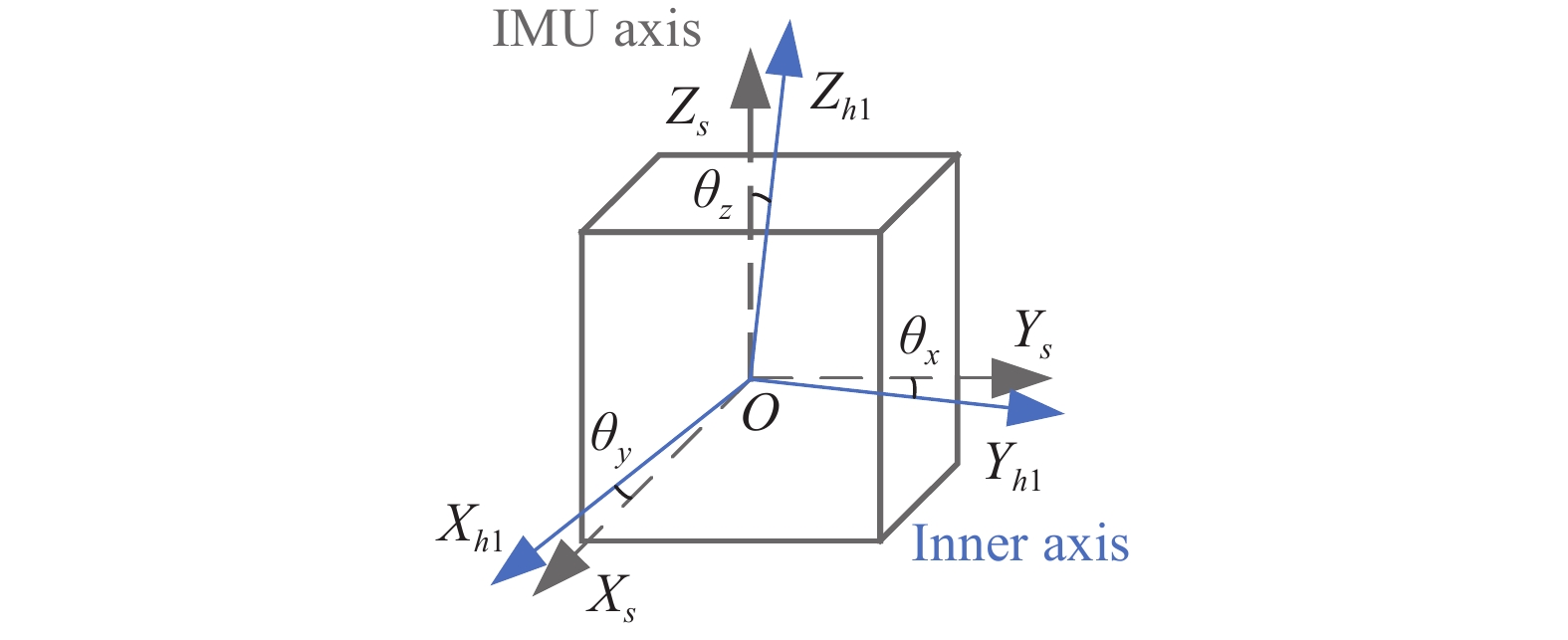
IMU坐标系(s系):定义IMU坐标系为与IMU三个方向敏感轴对齐的正交坐标系,如图1中$O{X_s}{Y_s}{Z_s}$所示。IMU坐标系s固联于内轴架;

图 1 IMU坐标系与内框坐标系间的非正交误差
Figure 1. Nonorthogonal angles between IMU frame and inner rotating frame
内框坐标系(h1系):内框坐标系轴Zh1与内框转轴重合,如图1中$O{X_{h1}}{Y_{h1}}{Z_{h1}}$所示。内框坐标系跟随内框转轴在空间中转动;
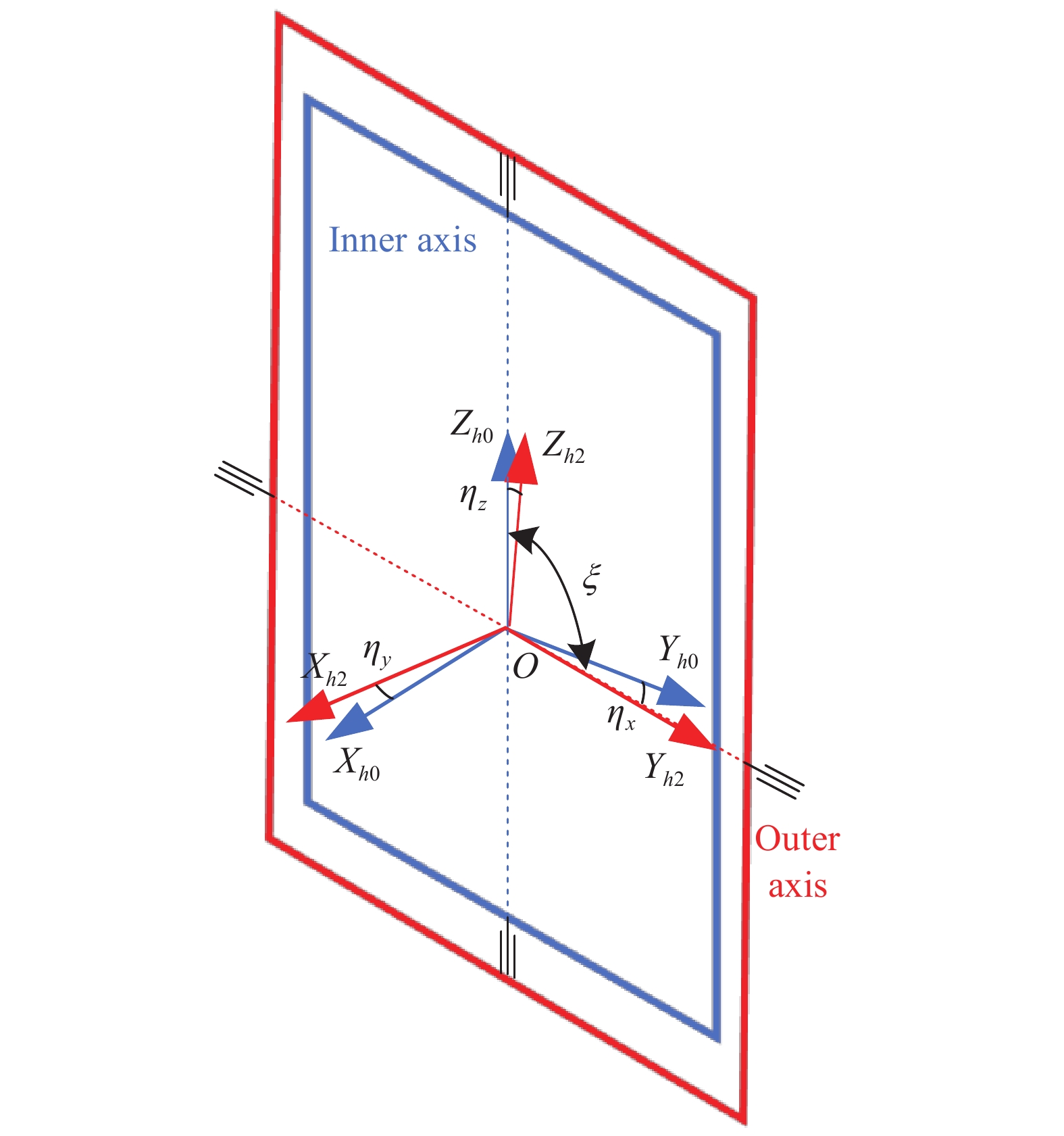
内框零位坐标系(h0系):定义内框转轴位于零位时的坐标系为内框零位坐标系h0,如图2中$O{X_{h0}}{Y_{h0}}{Z_{h0}}$所示。内框零位坐标系h0与外框架固联;
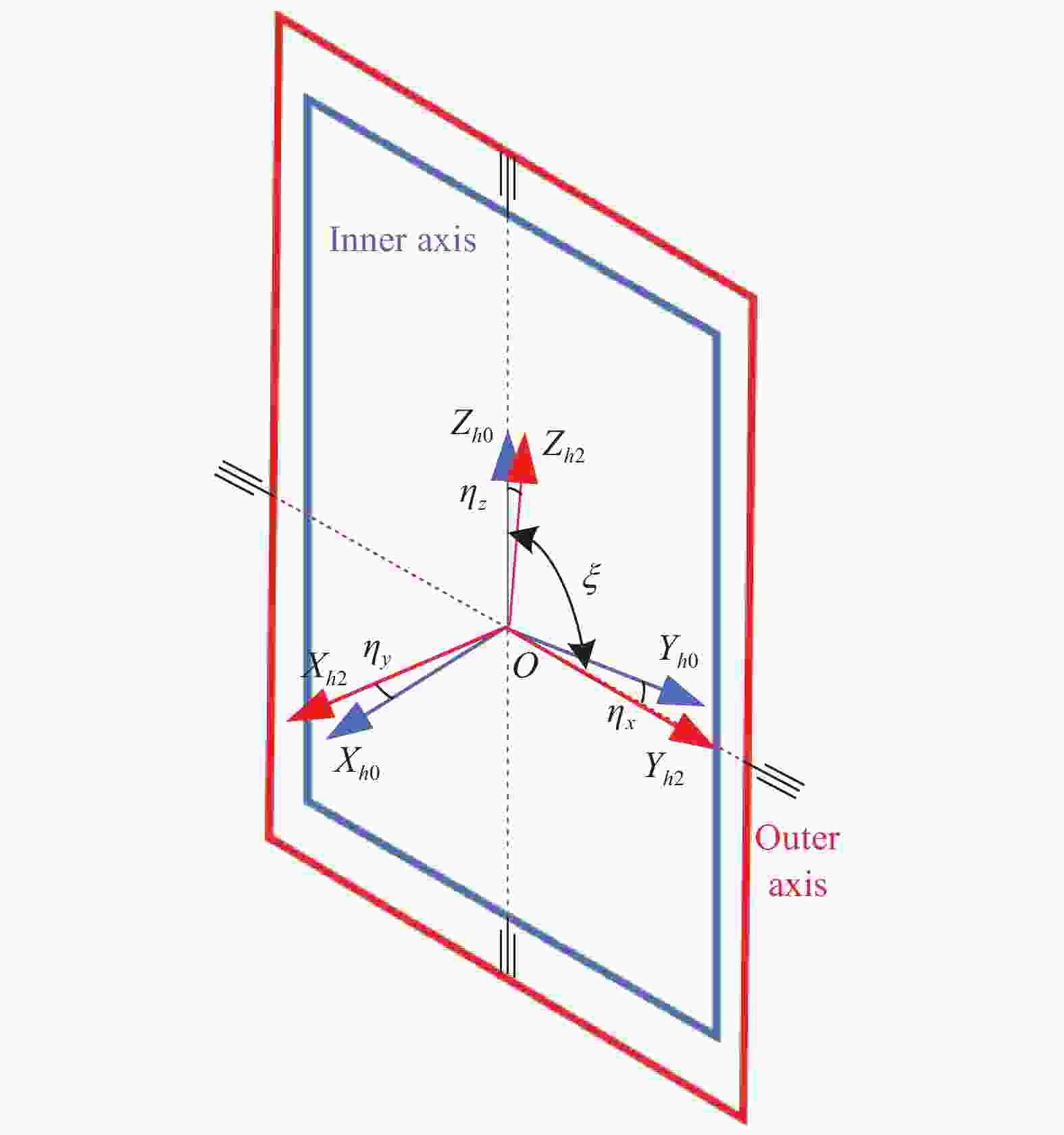
图 2 内框零位坐标系与外框坐标系间的非正交误差
Figure 2. Nonorthogonal angles between inner rotating frame and outer rotating frame
外框坐标系(h2系):外框坐标系轴Yh2与外框转轴重合,如图2中$O{X_{h2}}{Y_{h2}}{Z_{h2}}$所示。内框转轴和外框转轴间的非正交角为$\zeta $;外框架处于零位的坐标系与载体坐标系b重合。
双轴旋转激光惯导中,如果转位机构的内框转动角度为α,外框转动角度为β,则内框坐标系到内框零位坐标系的姿态转移矩阵${{{{\boldsymbol{C}}}}}_{h1}^{h0}(\alpha )$、载体坐标系到外框坐标系的姿态转移矩阵${{{{\boldsymbol{C}}}}}_b^{h2}(\beta )$分别为:
$$ {{{{\boldsymbol{C}}}}}_{h1}^{h0}(\alpha ) = \left[ {\begin{array}{*{20}{c}} {\cos \alpha }&{ - \sin \alpha }&0 \\ {\sin \alpha }&{\cos \alpha }&0 \\ 0&0&1 \end{array}} \right] $$ (1) $$ {{{{\boldsymbol{C}}}}}_b^{h2}(\beta ) = \left[ {\begin{array}{*{20}{c}} {\cos \beta }&0&{ - \sin \beta } \\ 0&1&0 \\ {\sin \beta }&0&{\cos \beta } \end{array}} \right] $$ (2) -
IMU坐标系与内框坐标系的空间相对位置如图1所示,$O{X_s}{Y_s}{Z_s}$表示IMU坐标系,$O{X_{h1}}{Y_{h1}}{Z_{h1}}$表示内框坐标系,IMU坐标系与内框坐标系固联。由于IMU安装在内框架上时无法保证IMU坐标系与内框坐标系的完全正交,因此两个坐标系的三轴向间存在非正交误差角$ {\theta _x},{\theta _y},{\theta _z} $,由IMU坐标系到内框坐标系的姿态转移矩阵为:
$$ \begin{split} {{{{\boldsymbol{C}}}}}_s^{h1} =& \left[ {\begin{array}{*{20}{c}} {\cos {\theta _y}\cos {\theta _\textit{z}} - \sin {\theta _y}\sin {\theta _\textit{z}}\sin {\theta _x}} \\ { - \sin {\theta _\textit{z}}\cos {\theta _x}} \\ {\sin {\theta _y}\cos {\theta _\textit{z}} + \cos {\theta _y}\sin {\theta _\textit{z}}\sin {\theta _x}} \end{array}} \right. \\& \left. {\begin{array}{*{20}{c}} {\cos {\theta _y}\cos {\theta _\textit{z}} + \sin {\theta _y}\cos {\theta _\textit{z}}\sin {\theta _x}}&{ - \sin {\theta _y}\cos {\theta _x}} \\ {\cos {\theta _\textit{z}}\cos {\theta _x}}&{\sin {\theta _x}} \\ {\sin {\theta _y}\sin {\theta _\textit{z}} - \cos {\theta _y}\cos {\theta _\textit{z}}\sin {\theta _x}}&{\cos {\theta _y}\cos {\theta _x}} \end{array}} \right] \end{split}$$ (3) 由于非正交误差角$ {\theta _x},{\theta _y},{\theta _\textit{z}} $通常较小,因此基于小角假设公式(3)可近似为:
$$ {{{{\boldsymbol{C}}}}}_s^{h1} = \left[ {\begin{array}{*{20}{c}} 1&{{\theta _\textit{z}}}&{ - {\theta _y}} \\ { - {\theta _\textit{z}}}&1&{{\theta _x}} \\ {{\theta _y}}&{ - {\theta _x}}&1 \end{array}} \right] $$ (4) -
内框坐标系与外框坐标系的空间相对位置如图2所示,$O{X_{h0}}{Y_{h0}}{Z_{h0}}$表示内框零位坐标系,$O{X_{h2}}{Y_{h2}}{Z_{h2}}$表示外框坐标系,内框零位坐标系固联于外框架。由于内框转轴和外框转轴间的安装无法完全正交,内框零位坐标系和外框坐标系间存在非正交误差角${\eta _x},{\eta _y},{\eta _\textit{z}}$。类似于1.2.1小节的推导,由内框零位坐标系h0到外框坐标系h2的姿态转移矩阵为:
$$ {{{{\boldsymbol{C}}}}}_{h0}^{h2} = \left[ {\begin{array}{*{20}{c}} 1&{{\eta _\textit{z}}}&{ - {\eta _y}} \\ { - {\eta _\textit{z}}}&1&{{\eta _x}} \\ {{\eta _y}}&{ - {\eta _x}}&1 \end{array}} \right] $$ (5) -
建立双轴旋转激光惯导转位机构的非正交误差模型后,可以建立IMU到载体间的姿态传递模型。载体姿态的表达式为:
$$ {{{{\boldsymbol{C}}}}}_b^n = {{{{\boldsymbol{C}}}}}_s^n{{{{\boldsymbol{C}}}}}_{h1}^s{{{{\boldsymbol{C}}}}}_{h0}^{h1}\left( \alpha \right){{{{\boldsymbol{C}}}}}_{h2}^{h0}{{{{\boldsymbol{C}}}}}_b^{h2}\left( \beta \right) $$ (6) 式中:${{{{\boldsymbol{C}}}}}_s^n$为IMU通过捷联惯性导航解算得到的IMU姿态,捷联惯性导航解算可参考文献[7]. ${{{{\boldsymbol{C}}}}}_{h1}^s = {\left( {{{{{\boldsymbol{C}}}}}_s^{h1}} \right)^{\rm{T}}}$,$ {\left( \cdot \right)^{\rm{T}}} $表示矩阵的转置。因此,如果需要得到高精度的载体姿态,需要把非正交误差矩阵${{{{\boldsymbol{C}}}}}_{h1}^s$与${{{{\boldsymbol{C}}}}}_{h2}^{h0}$标定准确。
-
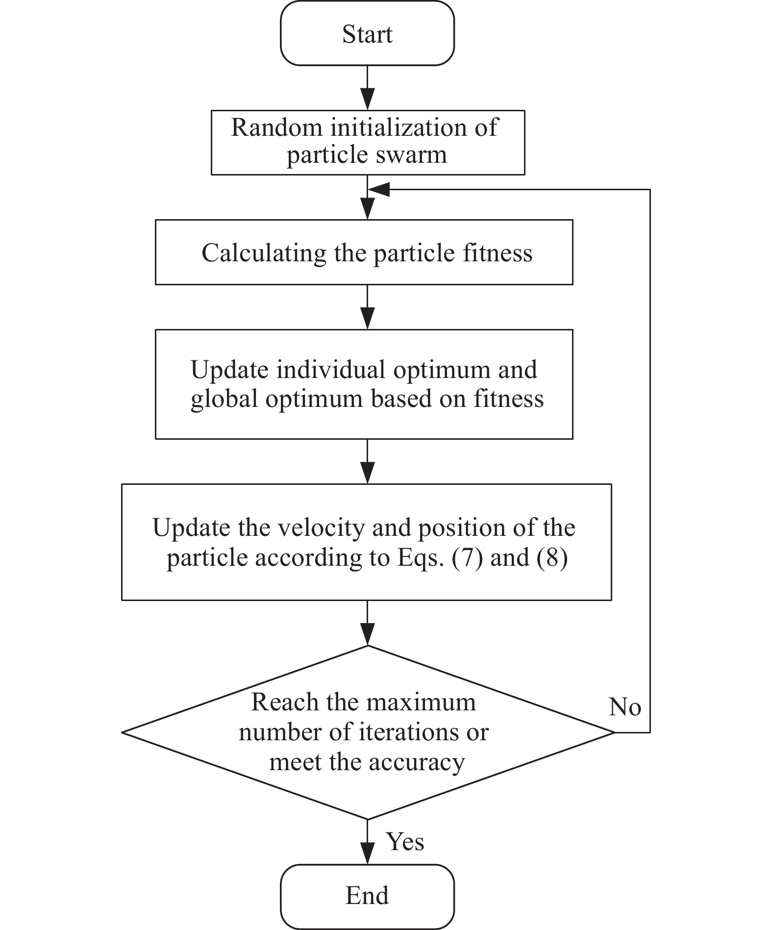
粒子群优化(Particle Swarm Optimization, PSO)算法是一种以鸟类觅食行为为模型的基于种群的随机搜索方法。PSO算法建立一个由多个个体(称为粒子)组成的种群,其中每个粒子代表着一个潜在的解,通过个体粒子的简单行为和种群内部的信息交互来实现解决问题的智能求解[8]。粒子的当前位置是相应优化问题的潜在解。粒子的飞行过程就是最优解的搜索过程。粒子的飞行速度可以根据粒子历史最优位置和种群历史最优位置动态调整。搜索过程中具有最佳适应度值的第i个粒子的位置存储在一个变量中,称为个体最优位置$pbes{t_i}$,而具有最佳适应度的粒子在种群中的位置称为全局最优位置$gbest$。粒子拥有两个状态向量,即速度向量$ {V_i} $和位置向量$ {X_i} $,代表粒子在搜索空间中的进化状态。在迭代过程中,更新速度向量$ {V_i} $和位置向量$ {X_i} $,其更新进化规则如公式(7)及(8)所示:
$$ \begin{split} {V_i}\left( {g + 1} \right) = &\omega {V_i}\left( g \right) + {c_1}{r_1}\left( {pbes{t_i}\left( g \right) - {X_i}\left( g \right)} \right) + \\& {c_2}{r_2}\left( {gbest\left( g \right) - {X_i}\left( g \right)} \right) \end{split}$$ (7) $$ {X_i}\left( {g + 1} \right) = {X_i}\left( g \right) + {V_i}\left( {g + 1} \right) $$ (8) 式中:g表示当前迭代次数,总迭代次数为G;i为当前粒子,粒子群中粒子总数为N;$ \omega $为权重因子,用以平衡局部搜索与全局搜索的权重;$ {c_1},{c_2} $为学习因子,分别表征粒子向自身和其他粒子学习的能力,通常在$\left( {0,2} \right)$之间取值;$ {r_1},{r_2} $为介于$\left( {0,1} \right)$之间的随机数。
粒子群优化算法的具体步骤如图3所示。由图3可知,只要构建合适的适应度函数,就可以通过粒子群优化算法得到适应度函数值的最优解,即最优粒子位置。

图 3 粒子群优化算法流程图
Figure 3. The flow diagram of PSO algorithm
-
由上述粒子群优化算法的基本原理可知,构建合适的粒子与适应度函数是粒子群优化算法的关键。通过构建合适的粒子与适应度函数,即可将非正交误差的标定问题转化为优化问题[9]。
非正交误差的表现形式如公式(4)和公式(5),可以看到公式中包含6个失准角$ {\theta _x},{\theta _y},{\theta _\textit{z}},{\eta _x},{\eta _y},{\eta _\textit{z}} $,定义粒子群中每个粒子包含6个参数,分别对应非正交误差的6个失准角,第i个粒子$ {{{p}}}_{}^i $的表现形式为:
$$ {{{p}}}_{}^i = \left[ {\begin{array}{*{20}{c}} {p_{\theta x}^i}&{p_{\theta y}^i}&{p_{\theta \textit{z}}^i}&{p_{\eta x}^i}&{p_{\eta y}^i}&{p_{\eta \textit{z}}^i} \end{array}} \right] $$ (9) 将第i个粒子编排为非正交误差的形式为:
$$ {\left( {{{{{\boldsymbol{C}}}}}_s^{h1}} \right)^{pi}} = \left[ {\begin{array}{*{20}{c}} 1&{p_{\theta \textit{z}}^i}&{ - p_{\theta y}^i} \\ { - p_{\theta \textit{z}}^i}&1&{p_{\theta x}^i} \\ {p_{\theta y}^i}&{ - p_{\theta x}^i}&1 \end{array}} \right] $$ (10) $$ {\left( {{{{{\boldsymbol{C}}}}}_{h0}^{h2}} \right)^{pi}} = \left[ {\begin{array}{*{20}{c}} 1&{p_{\eta \textit{z}}^i}&{ - p_{\eta y}^i} \\ { - p_{\eta \textit{z}}^i}&1&{p_{\eta x}^i} \\ {p_{\eta y}^i}&{ - p_{\eta x}^i}&1 \end{array}} \right] $$ (11) 式中:${\left( {{{{{\boldsymbol{C}}}}}_s^{h1}} \right)^{pi}}$为第i个粒子编排成的由IMU坐标系到内框坐标系的姿态转移矩阵;${\left( {{{{{\boldsymbol{C}}}}}_{h0}^{h2}} \right)^{pi}}$为第i个粒子编排成的由内框零位坐标系到外框坐标系的姿态转移矩阵。
以双轴旋转惯导提取出的载体姿态误差的均方根误差为适应度,构建适应度函数。定义适应度函数为:
$$ {{F}}\left( {{{{{p}}}^i}} \right) = \sqrt {\frac{1}{T}\sum\limits_{t = 1}^T {\left( {dcm2eul{{\left( {{{\left( {{\tilde {{{\boldsymbol{C}}}}}_n^{b,0}} \right)}^{pi}} \times {{\left( {{\tilde {{{\boldsymbol{C}}}}}_{b,t}^n} \right)}^{pi}}} \right)}^2}} \right)} } $$ (12) 式中:${{F}}\left( {{{{{p}}}^i}} \right) $为补偿第i个粒子编排的非正交误差后,解算出的载体姿态的均方根误差; $dcm2 eul( {{( {{\tilde {{{\boldsymbol{C}}}}}_n^{b,0}} )}^{pi}} \times {{( {{\tilde {{{\boldsymbol{C}}}}}_{b,t}^n} )}^{pi}} )$表示将括号里的姿态矩阵转换为欧拉角;$ \times $表示矩阵叉乘;${\left( {{\tilde {{{\boldsymbol{C}}}}}_n^{b,0}} \right)^{pi}}$为补偿第i个粒子编排的非正交误差后由精对准得到的导航系到载体的姿态转移矩阵,其中${\tilde {{{\boldsymbol{C}}}}}_n^{b,0}$上标0表示0时刻,${\left( {{\tilde {{{{{\boldsymbol{C}}}}}}}_n^{b,0}} \right)^{pi}}$的计算公式见公式(13);${\left( {{\tilde {{{\boldsymbol{C}}}}}_{b,t}^n} \right)^{pi}}$为补偿第i个粒子编排的非正交误差后由惯性解算得到的t时刻的载体姿态矩阵, ${\left( {{\tilde {{{\boldsymbol{C}}}}}_{b,t}^n} \right)^{pi}}$的计算公式见公式(14);${\left( {{\tilde {{{\boldsymbol{C}}}}}_n^{b,0}} \right)^{pi}} \times {\left( {{\tilde {{{\boldsymbol{C}}}}}_{b,t}^n} \right)^{pi}}$表示经过第i个粒子编排的非正交误差补偿后t时刻载体姿态的误差。
$$ {\left( {{\tilde {{{\boldsymbol{C}}}}}_n^{b,0}} \right)^{pi}} = {\left( {{{{{\boldsymbol{C}}}}}_{s,0}^n{{\left( {{{{{\boldsymbol{C}}}}}_{h1}^s} \right)}^{pi}}{{{{\boldsymbol{C}}}}}_{h0}^{h1}\left( {{\alpha _0}} \right){{\left( {{{{C}}}_{h2}^{h0}} \right)}^{pi}}{{{{\boldsymbol{C}}}}}_b^{h2}\left( {{\beta _0}} \right)} \right)^{\rm{T}}} $$ (13) $$ {\left( {{\tilde {{{\boldsymbol{C}}}}}_{b,t}^n} \right)^{pi}} = {{{{\boldsymbol{C}}}}}_{s,t}^n{\left( {{{{{\boldsymbol{C}}}}}_{h1}^s} \right)^{pi}}{{{{\boldsymbol{C}}}}}_{h0}^{h1}\left( {{\alpha _t}} \right){\left( {{{{{\boldsymbol{C}}}}}_{h2}^{h0}} \right)^{pi}}{{{{\boldsymbol{C}}}}}_b^{h2}\left( {{\beta _t}} \right) $$ (14) 式中:${{{{\boldsymbol{C}}}}}_{s,t}^n$为t时刻通过捷联算法解算出的IMU姿态;$ {\alpha _t} $和$ {\;\beta _t} $分别表示t时刻内框测角信息和外框测角信息;t=0时,表示导航初始时刻;${{{{\boldsymbol{C}}}}}_{s,0}^n$为通过初始对准得到的IMU在导航初始时刻精确的姿态,初始对准过程可参考文献[7,10]。
显然,解算出的载体姿态的均方根误差越小,适应度值越小,相对应的粒子就越优。按照图3的流程,首先随机初始化粒子群,再评估粒子群的适应度函数,然后寻找出个体最优粒子以及全局最优,进一步地,根据公式(7)和公式(8)更新粒子的位置和速度,通过迭代,即可寻优得到全局最优解。全局最优解是使载体姿态误差最小的解,最后将全局最优解作为双轴旋转激光惯导的非正交误差标定值。
-
为了验证该非正交误差优化标定方法的有效性,文中开展了双轴旋转调制惯导系统的标定试验以及导航试验。

图 4 双轴旋转激光惯导系统
Figure 4. Dual-axis rotational laser INS
试验设备包括国防科大自主研发的双轴旋转激光惯导系统,如图4所示,以及一套GNSS设备以获得试验地点的参考位置。双轴旋转激光惯导的惯性测量单元的技术指标如表1所示。将双轴旋转激光惯导系统放置于静基座水平操作台,首先进行双位置初始对准以得到惯性测量单元的初始姿态,随后进入16次序旋转调制导航阶段[11-12]。将旋转一个16次序周期的数据送入粒子群优化算法进行标定,即可得到非正交误差的标定值。实际上只需一段包含内框转动和外框转动的数据,且数据越短,标定速度越快,但是为了减小姿态随机误差对标定结果的影响,选取一个16次序旋转周期的数据。时间不同步误差也是影响载体姿态的重要因素之一[6],由于文中研究重点在非正交误差的标定,所以标定试验以及导航试验均提前标定并补偿了时间不同步误差。
表 1 惯性测量单元技术指标
Table 1. IMU characteristics
Characteristics Parameters Gyro drift stability/(°)·h−1 ${ { {0.005} } }$ Gyro stochastic error/(°)·h−1/2 ${ { { 0.000\;5} } }$ Gyro scale factor stability/ppm $2$ Accelerometer bias stability/μg $20$ Sampling frequency/Hz $200$ 在粒子群优化算法的参数设定中,根据文献[8-9]及工程经验,设定参数如表2所示。
表 2 PSO参数设置
Table 2. PSO parameters
PSO parameters Setting value $\omega $ 0.8 ${c_1},{c_2}$ 2, 2 $ {V_{\min }},{V_{\max }} $ −1, 1 N 20 G 150 图5为进行50次蒙特卡洛试验的适应度值收敛过程曲线图,可以看出,随着迭代次数的增加,适应度值都可以得到很好地收敛,不会陷入局部最优。

图 5 粒子群算法适应度值收敛过程
Figure 5. Fitness value convergence process of PSO algorithm
选取50次蒙特卡洛试验中随机的一次结果作为非正交误差的标定值,标定结果见表3。
表 3 非正交误差标定结果
Table 3. The calibration result of nonorthogonal angles
Angles Value/(°) Angles Value/(°) $ {\theta _x} $ −0.000 279 $ {\eta _x} $ 0.000721 $ {\theta _y} $ −0.000 963 $ {\eta _y} $ −0.000 806 $ {\theta _\textit{z}} $ −0.002 212 $ {\eta _\textit{z}} $ −0.009 205 -
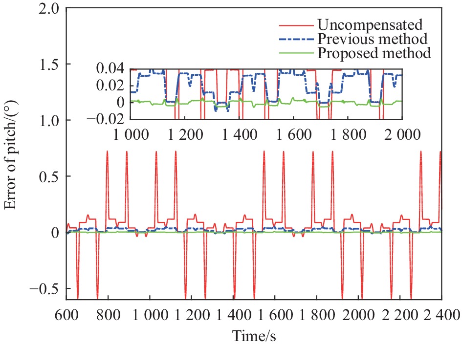
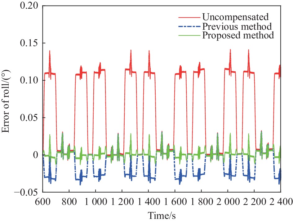
将双轴旋转激光惯导放置于静基座平台,进行600 s初始对准,得到初始姿态,然后进入16次序旋转调制导航阶段。将表3的标定结果代入载体姿态解算过程,可得到载体姿态信息。由于导航试验期间惯导系统放置于静基座平台,因此在导航坐标系下的姿态不变,此时通过评判载体姿态的波动程度即可评估精度,也可将载体姿态扣除初始对准得到的初始姿态,即为载体姿态误差。图6~8为解算得到的载体姿态误差,其中红色曲线为未经过非正交误差标定得到的载体姿态,蓝色曲线为利用文献[6]的方法标定补偿后得到的载体姿态。绿色曲线为利用所提出的基于粒子群算法的非正交误差标定方法补偿后得到的载体姿态。图6~8中,在静基座情况下如果不补偿转位机构非正交误差,载体姿态有着较大的波动,这是由于非正交误差与旋转耦合产生了振荡的姿态误差;利用文献[6]的方法对非正交误差进行标定,姿态误差得到明显的抑制,但经过分析,此方法易受到陀螺安装误差与刻度因数误差的影响导致标定精度下降;文中提出的标定方法补偿非正交误差后误差最小,由非正交误差引起的载体姿态误差得到有效抑制。

图 6 载体俯仰角误差
Figure 6. Vehicle pitch error

图 7 载体横滚角误差
Figure 7. Vehicle roll error

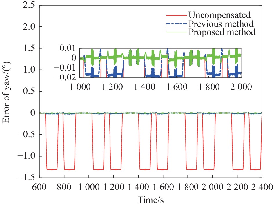
图 8 载体航向角误差
Figure 8. Vehicle yaw error
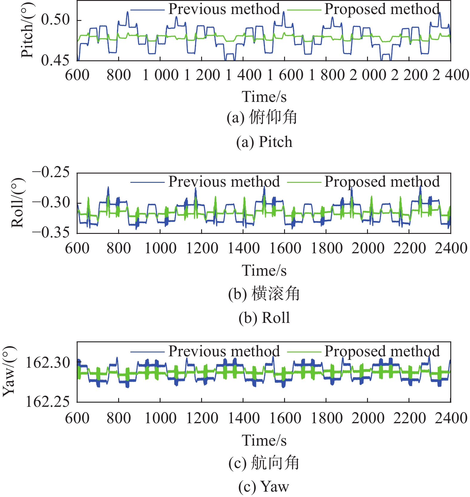
从图9载体姿态可以看出,经过补偿后波动明显下降,其中文中提出的方法相对于传统方法,姿态的波动更小。双轴旋转激光惯导转位机构电锁控制误差和转轴小量晃动引起的误差成为载体姿态误差的主要来源[6]。
表4为载体姿态均方根误差对比,相对于不补偿转位机构非正交误差,利用粒子群优化算法标定并补偿非正交误差的方法使载体俯仰角误差下降了98.67%,横滚角误差下降了93.07%,航向角误差下降了99.74%;相对于传统方法,文中提出方法的载体俯仰角误差下降89.29%,横滚角误差下降73%,航向角误差下降81.39%。
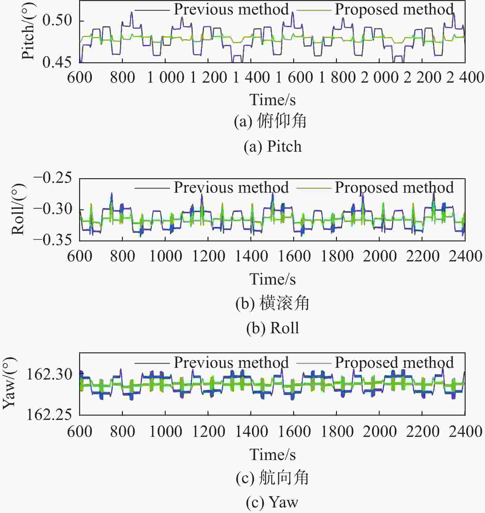
图 9 载体姿态
Figure 9. Vehicle attitude
表 4 载体姿态均方根误差对比
Table 4. Vehicle attitude RMSE comparison
Methods RMSE/(°) Pitch Roll Yaw Uncompensated 0.202 5 0.077 9 0.926 3 Previous method 0.025 2 0.020 0 0.012 9 Proposed method 0.002 7 0.005 4 0.002 4 为了验证文中提出的非正误差优化标定方法的重复性,将3.1节中50次蒙特卡洛标定试验的结果全部进行载体姿态解算,可以得到如图10所示的50次导航试验得到的载体姿态RMSE图。从图10中可以看出,在随机初始化粒子群的50次蒙特卡洛试验中,姿态的RMSE基本稳定,仅有1次试验波动较大,但振幅最大不超过0.001 3°,在可接受范围内,验证了所提出方法的重复性。
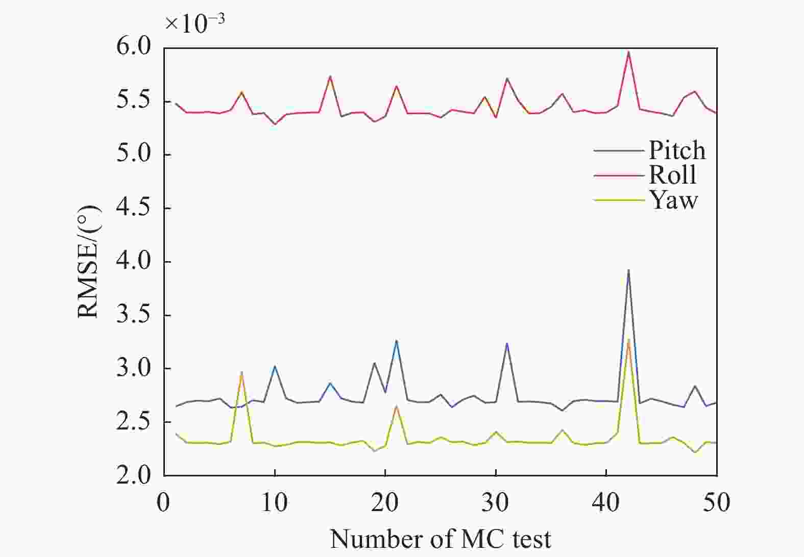
图 10 50次蒙特卡洛试验姿态RMSE
Figure 10. Attitude RMSE of 50 Monte Carlo test
-
文中针对双轴旋转激光惯导中转位机构的非正交误差问题,提出了一种非正交误差优化标定方法。试验结果表明,所提出的非正交误差优化标定方法能够有效实现双轴旋转激光惯导转位机构非正交误差的标定,可以显著降低载体姿态误差,实现惯性测量单元的姿态信息与转位机构的解耦,得到了高精度的载体姿态信息。相对于传统方法,所提出的标定方法不仅精度更高,且不需要特定的旋转路径,操作简单。静基座情况下,惯导待机阶段执行任意双轴导航旋转方案即可进行现场标定。利用所提出的标定方法,双轴旋转惯导系统得以输出高精度姿态,可为长航时高精度自主导航提供保障。
文中所提出的非正交误差优化标定方法在静基座情况下标定精度较高,如果应用于舰船系泊等晃动基座情况的标定,标定精度会受到影响。可通过数字滤波器预先滤除晃动角运动信息,再利用文中方法进行标定,标定精度可达到与静基座相同水平。
Optimal calibration method for nonorthogonal errors in dual-axis rotational RLG INS
-
摘要: 旋转激光惯导系统无法直接解算得到载体的姿态信息。精确标定惯性测量单元与转位机构间的非正交误差是获得高精度载体姿态信息的前提。针对双轴旋转激光惯导系统转位机构的非正交误差标定问题,提出了一种非正交误差优化标定方法。首先,建立惯性测量单元、转位机构、内框架、外框架间的空间位置关系模型。然后,构建包含非正交误差的载体姿态传递模型。进一步将标定问题转换为优化问题,以载体姿态误差作为适应度值构建适应度函数。利用粒子群优化寻优适应度函数,实现非正交误差标定。利用双轴旋转激光惯导系统验证了所提方法的有效性,相对于传统标定方法,载体俯仰角误差下降89.29%,横滚角误差下降73%,航向角误差下降81.39%。Abstract:
Objective In the rotational ring laser gyro inertial navigation system, the rotary mechanism propels the inertial measurement unit (IMU) to rotate periodically concerning the vehicle. It takes work to get the attitude information directly. High-accuracy attitude information is essential for long-endurance high-accuracy autonomous navigation. High-accuracy vehicle attitude decoupling techniques for dual-axis rotational inertial navigation systems are of great practical importance. To extract the vehicle attitude information in the rotational laser inertial navigation system, decoupling the IMU attitude from the dual-axis attitude is necessary. However, there are inevitable nonorthogonal angles in the dual-axis rotational inertial navigation system. Installing the inner and outer axis frames cannot guarantee the inner axis zero frames, and the outer axis frame cannot be completely orthogonal. Similarly, when mounting the IMU on an inner axis frame, there is no guarantee that the IMU frame is entirely orthogonal to the inner axis frame. By calibrating the nonorthogonal errors, an accurate attitude transfer model can be established, and the accurate attitude information of the vehicle can be obtained. Methods An optimal calibration method for nonorthogonal errors in dual-axis rotational RLG INS is proposed. The proposed calibration method allows accurate calibration of nonorthogonal angles between the rotational axes of the dual-axis rotational inertial navigation system. Based on the mechanical structure of the dual-axis rotational inertial navigation system and the definition of the coordinate frame, the spatial relative position model between the coordinate frame was established, including the spatial position relationship between the outer and inner axis frame and the spatial position relationship between the IMU and the inner axis frame. The IMU's attitude to the vehicle's attitude transfer model is constructed, which includes the nonorthogonal angles. Furthermore, the calibration problem is converted into an optimization problem based on the attitude transfer model. A fitness function is constructed using the vehicle attitude error as the fitness. The particle swarm optimization algorithm finds the optimal global solution to the created fitness function. The nonorthogonal angles calibration of the dual-axis rotary mechanism is achieved. Results and Discussions Calibration tests and navigation tests were conducted to verify the effectiveness of the proposed nonorthogonal angles calibration method. The test equipment consisted of a dual-axis rotational modulated laser inertial navigation system self-developed by the National Defense University of Science and Technology (Fig.4) and a set of GNSS equipment to obtain the reference position of the test site. The specifications of the inertial measurement unit are shown (Tab.1). The parameters of the particle swarm optimization algorithm are set (Tab.2). The 30 Monte Carlo tests were conducted to verify that the PSO algorithm did not fall into a local optimum or fail to converge completely. The result shows the convergence of the fitness values for the 30 Monte Carlo tests (Fig.5). As the number of iterations increases, the fitness values converge well and do not fall into a local optimum. The results from a randomly selected set of 30 Monte Carlo tests are shown (Tab.3). The dual-axis rotational modulated laser inertial navigation system is placed on a static base platform. An initial alignment is performed for 600 s to obtain the initial attitude, followed by a 16-order navigation rotational modulated phase. The calibration results from Tab.3 are then substituted into the attitude solution process to get the vehicle's attitude information. The vehicle's attitude error is shown (Fig.6-8), where the red curve is the attitude without nonorthogonal angles calibration, and the blue curve is the vehicle attitude after calibration compensation using the conventional method. The green curve is the vehicle attitude obtained after compensating for the proposed calibration method. The solved vehicles attitude is shown (Fig.9). In the case of a static base, the actual vehicle attitude remains unchanged. If the nonorthogonal angles are not compensated, the vehicle's attitude calculated by IMU has a significant fluctuation due to the oscillating attitude error generated by the nonorthogonal angles. The statistical values of the vehicle attitude error are show (Tab.4). Compared with the conventional method, the pitch error is reduced by 89.29% with the proposed method, the roll error is reduced by 73%, and the yaw error is reduced by 81.39%. The repeatability of the proposed method was verified with the Monte Carlo tests (Fig.10). Conclusions An optimal calibration method for nonorthogonal errors in dual-axis rotational RLG INS is proposed. The experimental results show that the nonorthogonal angles can be effectively achieved with the proposed nonorthogonal angles calibration method, which can significantly reduce the vehicle attitude error and decouple the attitude information of the IMU from the rotating mechanism to obtain the vehicle attitude information with high accuracy. The proposed calibration method is more accurate than conventional methods and does not require a specific rotation path. The technique is simple to operate. The inertial navigation system can calibrate the nonorthogonal angles in situ by executing 16-position navigation paths during the standby phase. With the proposed calibration method, the dual-axis rotational inertial navigation system can output high-accuracy attitudes, guaranteeing high-accuracy autonomous navigation. -
图 1 IMU坐标系与内框坐标系间的非正交误差
Figure 1. Nonorthogonal angles between IMU frame and inner rotating frame
图 2 内框零位坐标系与外框坐标系间的非正交误差
Figure 2. Nonorthogonal angles between inner rotating frame and outer rotating frame
表 1 惯性测量单元技术指标
Table 1. IMU characteristics
Characteristics Parameters Gyro drift stability/(°)·h−1 ${ { {0.005} } }$ Gyro stochastic error/(°)·h−1/2 ${ { { 0.000\;5} } }$ Gyro scale factor stability/ppm $2$ Accelerometer bias stability/μg $20$ Sampling frequency/Hz $200$  下载: 导出CSV
表 2 PSO参数设置
Table 2. PSO parameters
PSO parameters Setting value $\omega $ 0.8 ${c_1},{c_2}$ 2, 2 $ {V_{\min }},{V_{\max }} $ −1, 1 N 20 G 150
下载: 导出CSV
表 3 非正交误差标定结果
Table 3. The calibration result of nonorthogonal angles
Angles Value/(°) Angles Value/(°) $ {\theta _x} $ −0.000 279 $ {\eta _x} $ 0.000721 $ {\theta _y} $ −0.000 963 $ {\eta _y} $ −0.000 806 $ {\theta _\textit{z}} $ −0.002 212 $ {\eta _\textit{z}} $ −0.009 205
下载: 导出CSV
表 4 载体姿态均方根误差对比
Table 4. Vehicle attitude RMSE comparison
Methods RMSE/(°) Pitch Roll Yaw Uncompensated 0.202 5 0.077 9 0.926 3 Previous method 0.025 2 0.020 0 0.012 9 Proposed method 0.002 7 0.005 4 0.002 4
下载: 导出CSV
-
[1] 王子超, 范会迎, 谢元平等. 捷联惯导系统复杂误差参数系统级标定方法[J]. 红外与激光工程, 2022, 51(07): 285-295. Wang Z, Fan H, Xie Y, et al. System-level calibration method for complex error coefficients of strapdown inertial navigation system [J]. Infrared and Laser Engineering, 2022, 51(7): 20210499. (in Chinese) [2] 谢元平, 范会迎, 王子超等. 双轴旋转调制捷联惯导系统旋转方案优化设计[J]. 中国惯性技术学报, 2021, 29(04): 421-427+436. Xie Y, Fan H, Wang Z, et al. Optimization design of rotation scheme for dual-axis rotation-modulation strapdown inertial navigation system [J]. Journal of Chinese Inertial Technology, 2021, 29(4): 421-427, 436. (in Chinese) [3] Gao W, Fang X, Liu F. Analysis on the influence of three-axis turntable nonorthogonal error on gyro calibration of SINS[C]//2012 IEEE International Conference on Mechatronics and Automation, 2012: 2429-2434. [4] Wang B, Ren Q, Deng Z, et al. A self-calibration method for nonorthogonal angles between gimbals of rotational inertial navigation system [J]. IEEE Transactions on Industrial Electronics, 2014, 62(4): 2353-2362. [5] Deng Z, Sun M, Wang B, et al. Analysis and calibration of the nonorthogonal angle in dual-axis rotational INS [J]. IEEE Transactions on Industrial Electronics, 2017, 64(6): 4762-4771. doi: 10.1109/TIE.2017.2652342 [6] 江一夫, 李四海, 严恭敏, 等. 基于双轴旋转调制惯性测量的载体导航信息提取方法[J]. 中国惯性技术学报, 2022, 30(03): 304-308+315. Jiang Y, Li S, Yan G, et al. Vehicle navigation information extraction method based on dual-axis rotation-modulation inertial measurement [J]. Journal of Chinese Inertial Technology, 2022, 30(3): 304-308, 315. (in Chinese) [7] 严恭敏, 翁浚. 捷联惯导算法与组合导航原理[M]. 西安: 西北工业大学出版社, 2019. [8] Liang J J, Qin A K, Suganthan P N, et al. Comprehensive learning particle swarm optimizer for global optimization of multimodal functions [J]. IEEE transactions on Evolutionary Computation, 2006, 10(3): 281-295. doi: 10.1109/TEVC.2005.857610 [9] Li D, Xu J, Zhu B, et al. A calibration method of DVL in integrated navigation system based on particle swarm optimization [J]. Measurement, 2022, 187: 110325. doi: 10.1016/j.measurement.2021.110325 [10] 高春峰, 魏国, 谢元平等. 二频机抖激光陀螺捷联惯导系统快速对准方法[J]. 红外与激光工程, 2014, 43(02): 375-381. Gao C, Wei G, Xie Y, et al. Fast alignment of mechanically dithered ring laser gyro SINS system [J]. Infrared and Laser Engineering, 2014, 43(2): 375-381. (in Chinese) [11] 于旭东, 龙兴武, 王宇等. 激光陀螺单轴旋转惯导系统多位置对准技术研究[J]. 传感技术学报, 2011, 24(06): 824-828. doi: 10.3969/j.issn.1004-1699.2011.06.009 Yu X, Long X, Wang Y, et al. Research on multi-position alignment in single-axial rotation inertial navigation system with ring laser gyroscope [J]. Chinese Journal of Sensors and Actuators, 2011, 24(6): 824-828. (in Chinese) doi: 10.3969/j.issn.1004-1699.2011.06.009 [12] Yuan B, Liao D, Han S. Error compensation of an optical gyro INS by multi-axis rotation [J]. Measurement Science and Technology, 2012, 23(2): 025102. doi: 10.1088/0957-0233/23/2/025102 -

 点击查看大图
计量
- 文章访问数: 100
- HTML全文浏览量: 44
- PDF下载量: 22
- 被引次数: 0

