


 下载:
下载:


-
雷达天线指向一般通过基座惯导姿态结合雷达码盘传递得到,雷达轴系误差、编码器误差等因素对雷达天线指向测量的影响不容忽略,为回避轴系误差的影响,贾将伟[1]提出将惯导安装在雷达天线上,惯导随天线转动,对天线指向进行直接测量,这种高动态应用环境对激光陀螺测量的实时性提出了更高的要求。
为减小激光陀螺闭锁效应的影响,通常采用的方法是加入正弦信号使陀螺大部分时间从锁区偏置出来,因此陀螺输出中包含抖动信息,导航解算时必须去除人为加入的抖动信号,即对陀螺输出进行解调。激光陀螺常用的解调方法有整周期采样法、高频采样滤波法和抖动剥除法。整周期采样法虽能有效地去除陀螺输出信号中的抖动成分,但无法去除高频信号与随机噪声[2];高速采样低通滤波解调法是目前最常用的方法,但由于使用了FIR滤波器,不可避免地使所有频率成分都产生了一定时间的延迟,比较适合低噪声高精度导航场合[2],时间延迟会导致较大的跟踪误差,不适用于雷达天线等高动态跟踪中的应用,极大地限制了机械抖动激光陀螺在雷达天线等快速跟踪中的应用。基于抖动剥除的解调方案具有零时延的特点,在去除陀螺输出信号中的抖动成分的同时还能够实时输出陀螺角速率信息,主要应用于中低精度跟踪场合[3]。
国外学者就抖动剥除已展开了系统的研究[4-8], K.Banerjee[9]提出了一种改进的抖动剥除方案,该方案在抖动信号的衰减和陀螺输出时延方面都是最优的,但滤波器阻带和通带的选择不是通用的。Bernard Widrow [10]提出了一种自适应噪声消除的最优滤波方法,由于只是初步分析,该方法仍需完善;国内学者也对自适应滤波的抖动剥除开展了研究,对陀螺所有数据进行剥除,解调精度不及高速采样低通滤波且存在少量时延[11-14]。张庆华[2]对最小二乘(LS)估计、最小均方(LMS)自适应滤波和递归最小二乘(RLS)自适应滤波的抖动剥除算法进行了理论分析和实验研究,但该研究中抖动反馈信号是从抖动控制回路中的角速率传感器中引出,陀螺输出接口需要专门定制。张迪[15]提出将自适应陷波器用于抖动剥除,先进行抖动剥除,再对剥除结果进行FIR滤波,这样导航解算中会累积性引入抖动剥除误差,影响导航精度。
文中针对激光陀螺惯导安装在雷达天线上进行随转测量的大角度运动情况,创新性地提出了一种将FIR低通滤波和抖动剥除相结合的实时测量方法,FIR实现带延迟的精确测量,抖动剥除对FIR时间延迟段进行精确补偿,综合利用了FIR低通滤波高精度和抖动剥除无延迟的优点,并进行了实验验证。
-
抖动剥除是基于抖动反馈信号与陀螺输出信号中的抖动偏频信号的相关性,通过一定的算法实现对抖动反馈信号幅度和相位的实时调整,在陀螺输出信号中扣除调节后的抖动反馈信号即可实现信号的解调[3],且抖动剥除后的输出信号是实时的。
对于机械抖动激光陀螺,在$ t $~$ t + \Delta t $时间内,陀螺计数脉冲$ N $可以表示为[2]:
$$ \begin{split} N = & S\int_t^{t + \Delta t} {\mathop \varOmega \nolimits_d } \cos (\mathop \omega \nolimits_d t){\rm{d}}t + {{S}}\int_t^{t + \Delta t} {\mathop \varOmega \nolimits_b } {\rm{d}}t + \varepsilon (t) =\\ & \frac{{S\mathop \varOmega \nolimits_d }}{{\mathop \omega \nolimits_d }}\cos \left( {\mathop \omega \nolimits_d t + \frac{{\mathop \omega \nolimits_d \Delta t}}{2}} \right)\sin \left( {\frac{{\mathop \omega \nolimits_d \Delta t}}{2}} \right) + {{S}} \int_t^{t + \Delta t} {\mathop \varOmega \nolimits_b } {\rm{d}}t + \varepsilon (t) =\\ & {\text{ }}A\sin (\mathop \omega \nolimits_d t + \varphi ) + {{S}}\int_t^{t + \Delta t} {\mathop \varOmega \nolimits_b }{\rm{ d}}t + \varepsilon (t) \end{split}$$ (1) 式中:$ \mathop \varOmega \nolimits_d \cos (\mathop \omega \nolimits_d t) $为抖动偏频角速度;$ \mathop \varOmega \nolimits_b $为载体转动角速度;$ S $为比例系数;$ A = \dfrac{{S\mathop \varOmega \nolimits_d }}{{\mathop \omega \nolimits_d }}\sin \left( {\dfrac{{\mathop \omega \nolimits_d \Delta t}}{2}} \right) $和$ \varphi = \dfrac{{\mathop \omega \nolimits_d \Delta t - \pi }}{2} $为抖动偏频引起的正弦幅度和相位;$ \varepsilon (t) $为激光陀螺的随机输出。
记$A\sin (\mathop \omega \nolimits_d t + \varphi ) = \mathop N\nolimits_{{\rm{dither}}}$, $S \displaystyle \int_t^{t + \Delta t} {\mathop \varOmega \nolimits_b } {\rm{d}}t = \mathop N\nolimits_{{\rm{base}}}$,则公式(1)可改写为:
$$ \mathop {N = N}\nolimits_{{\rm{dither}}} + \mathop N\nolimits_{{\rm{base}}} + \varepsilon (t) $$ (2) 式中:$ \mathop N\nolimits_{{\rm{dither}}} $为机械抖动引起的脉冲数;$ \mathop N\nolimits_{{\rm{base}}} $为载体转动角速率引起的脉冲数。
由$\mathop N\nolimits_{{\rm{dither}}} = A\sin (\mathop \omega \nolimits_d t + \varphi )$,整理后$\mathop N\nolimits_{{\rm{dither}}}$可表示为:
$$ \mathop N\nolimits_{{\rm{dither}}} = \mathop {\mathop K\nolimits_1 \cdot \Delta \mathop a\nolimits_1 + \mathop K\nolimits_2 \cdot \Delta \mathop a\nolimits_2 = K}\nolimits{\rm{^T}} a $$ (3) 式中:$ K = \mathop {\left[ {K_1,K_2} \right]}\nolimits^{\rm{T}} $为陀螺输出信号与抖动反馈信号幅度比和相位差相关的系数;$a = \mathop {\left[ {\Delta a_1,\Delta a_2} \right]}\nolimits^{\rm{T}}$,其中$ \Delta a_1 $为抖动反馈信号,$ \Delta a_2 $为抖动反馈信号的正交信号。
由于得到抖动反馈信号的正交信号较为复杂,且高速采样时间间隔较短,对公式(3)做进一步的近似,用抖动反馈信号$ n $时刻的采样值$ \Delta a_1(n) $和$ n - 1 $时刻的采样值$ \Delta a_1(n - 1) $来替代抖动反馈信号的正交信号[2]。公式(3)可以改写为:
$$ \mathop N\nolimits_{{\rm{dither}}} = w_1\mathop { \cdot \Delta a_1(n) + w_2 \cdot \Delta a_1(n - 1) = w}\nolimits^{\rm{T}} a_1 $$ (4) 式中:$ w = \mathop {\left[ {\mathop w\nolimits_1 ,\mathop w\nolimits_2 } \right]}\nolimits^{\rm{T}} $为抖动剥除增益因子;$\mathop a\nolimits_1 = [ \Delta a_1(n), \Delta a_1(n - 1) ] ^{\rm{T}}$为抖动反馈信号$ n $时刻及$ n - 1 $时刻的采样值。
根据公式(4),只要求出增益因子并得到抖动反馈信号$ n $时刻和$ n - 1 $时刻的采样值就能得到抖动偏频估计量$ \mathop {\hat N}\nolimits_{{\rm{dither}}} $,陀螺角速率信息可表示为:
$$ \mathop N\nolimits_{{\rm{base}}} = N - \hat N_{\text{dither}} $$ (5) -
Kalman滤波算法是一种基于状态空间模型的最优状态估计递推算法,具有可以对非平稳多维随机系统过程状态进行实时估计等显著优点,特别适合于动态处理过程[16]。文中采用Kalman滤波算法来实时跟踪抖动剥除的增益因子。
抖动剥除算法一般都是针对陀螺角增量数据进行抖动剥除,文中为避免时间延迟时间段的角增量剥除误差累积,直接对陀螺输出角度值进行抖动剥除。抖动反馈信号取为陀螺输出角度值的带通滤波信号,将低频角加速度视为随机游走过程,基于抖动反馈信号与抖动偏频信号的相关性,对陀螺增益因子进行动态跟踪,通过Kalman滤波对时延前后的抖动量进行实时计算。
Kalman滤波更新方程如下:
$$ \left\{\begin{array}{c} \hat{X}_{k / k-1}=\varPhi_{k / k-1} \hat{X}_{k-1} \\ P_{k / k-1}=\varPhi_{k / k-1} P_{k-1} \varPhi_{k / k-1}{\rm{^T}}+\varGamma_{k-1} Q_{k-1} \varGamma_{k-1}{\rm{^T}} \\ K_k=P_{k / k-1} H_k{\rm{^T}}\left(H_k P_{k / k-1} H_k{\rm{^T}}+R_k\right)^{-1} \\ \hat{X}_k=\hat{X}_{k / k-1}+K_k\left(Z_k-H_k \hat{X}_{k / k-1}\right) \\ P_k=\left(I-K_k H_k\right) P_{k / k-1} \end{array}\right. $$ (6) 式中:$ \varPhi_{ k/k - 1 }$为状态转移矩阵;$ \hat X_{k/k - 1} $为最优一步预测;$ \hat X_{k - 1} $和$ \hat X_k $分别为$ k - 1 $时刻和$ k $时刻的状态最优估计;$ P_{k - 1} $和$ P_k $分别为$ k - 1 $时刻和$ k $时刻的均方误差阵;$ P_{k/k - 1} $为状态一步预测均方误差阵;$ \varGamma _{k - 1} $为$ k - 1 $时刻的系统噪声分配矩阵;$ Q_{k - 1} $为$ k - 1 $时刻的量测噪声协方差矩阵;$ H_k $为$ k $时刻的量测矩阵;$ R_k $为$ k $时刻的量测噪声协方差矩阵;$ K_k $为$ k $时刻的滤波增益。
采用4维状态向量,即:
$$ X = \mathop {\left[ {\mathop w\nolimits_1 {\text{ }}\mathop w\nolimits_2 \;\;\theta_ {{k }}\;\;\;\theta _{{k - 1}}} \right]}\nolimits^{\rm{T}} $$ (7) 式中:$ \mathop w\nolimits_1 $、$ \mathop w\nolimits_2 $为增益因子;$ \theta _k $和$ \theta_{ k - 1 }$分别为$ k $时刻与$ k - 1 $时刻的低频角度。
为提高模型的跟踪速度,将低频角加速度视为随机游走过程,则有:
$$ \ddot \theta = \omega $$ (8) 式中:$ \ddot \theta $为陀螺低频角度的二阶微分;$ \omega $为随机噪声。
对公式(8)推导可得:
$$ \theta_ k = 2\theta_{ k - 1 }- \theta_{ k - 2} + \omega $$ (9) 式中:$ \theta_ k $、$ \theta _{k - 1} $、$ \theta _{k - 2} $分别为$ k $、$ k - 1 $、$ k - 2 $时刻的低频角度;$ \omega $为随机噪声。
由公式(9)可得状态转移矩阵为:
$$ \varPhi_{ k/k - 1} = \left[ {\begin{array}{*{20}{c}} 1&0&0&0 \\ 0&1&0&0 \\ 0&0&2&{ - 1} \\ 0&0&1&0 \end{array}} \right] $$ (10) 过程噪声协方差矩阵为:
$$ Q = \left[ {\begin{array}{*{20}{c}} {\mathop q\nolimits_1^2 }&0&0&0 \\ 0&{\mathop q\nolimits_2^2 }&0&0 \\ 0&0&{\mathop q\nolimits_3^2 }&0 \\ 0&0&0&0 \end{array}} \right] $$ (11) 式中:$ q_1 $与$ q_2 $分别为增益系数$w_1、w_2$的缓变参数;$ q_3 $为角速度驱动参数,跟踪陀螺角速度变化。
均方误差阵为:
$$ P = \left[ {\begin{array}{*{20}{c}} 1&0&0&0 \\ 0&1&0&0 \\ 0&0&{p_3}&0 \\ 0&0&0&{p_4} \end{array}} \right] $$ (12) 式中:$ p_3 $与$ p_4 $为角度直流量缓变参数。
系统的观测方程为:
$$ Z = HX $$ (13) 式中:$ Z $为量测向量,陀螺输出信号;$ H $为量测矩阵;$ X $为4维状态向量。
观测量$ Z $中包含陀螺实际角运动和人为加入的抖动信号,量测矩阵为:
$$ H = \left[ {\begin{array}{*{20}{c}} {y(k)}&{y(k - 1)}&1&0 \end{array}} \right] $$ (14) 式中:$ y(k) $为$ k $时刻采样的带通滤波值;$ y(k - 1) $为$ k - 1 $时刻采样的带通滤波值。
-
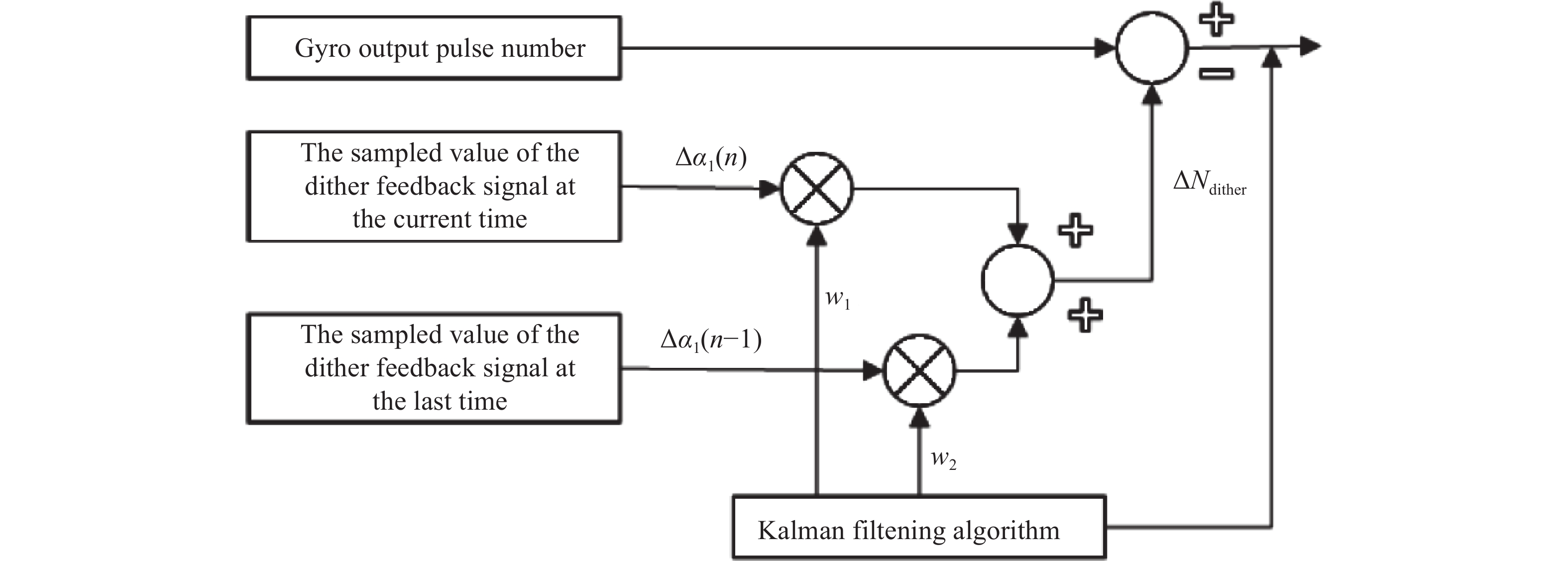
基于上述的抖动剥除理论分析,建立起的抖动剥除结构图如图1所示。
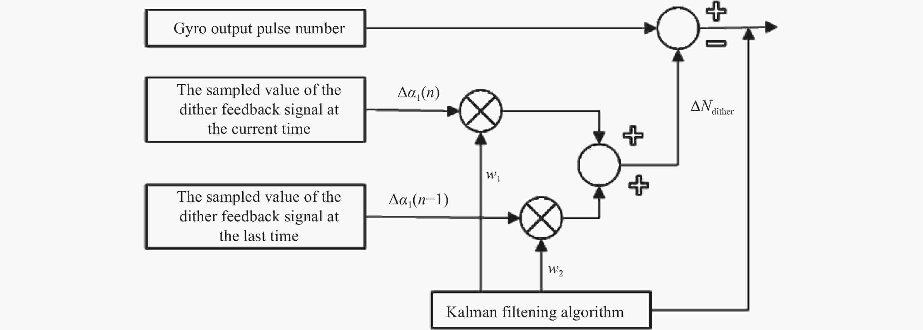
图 1 抖动剥除结构图
Figure 1. Dithering stripping structure diagram
实验方法如下:将90型激光陀螺惯性测量单元(IMU)安装在双轴转台上进行双轴旋转,采样频率为4 kHz,得到包含静态与动态的IMU实测数据。对激光陀螺数据进行抖动剥除测试,为避免对陀螺输出角增量滤波时子样误差的积累,直接对陀螺实测数据角度值进行低通滤波;将带通滤波陀螺数据作为抖动反馈信号;通过Kalman滤波算法计算得到抖动偏频估计量,最后陀螺输出脉冲数减去抖动偏频估计量即可得到陀螺转动角速度引起的脉冲数。
抖动剥除使用的带通滤波器指标如下:
$$ \begin{gathered} f_{n1 }= 31 3 \;{\rm{Hz}},f_{p1} = 338 \; {\rm{Hz}},fp2 = 348,f_{n2 }= 373 \\ \delta n_1 = 60 \; {\rm{dB}},\delta p = 10 \; {\rm{dB}},\delta n_2 = 60 \; {\rm{dB}} \\[-3pt] \end{gathered} $$ (15) 式中:$ f_{n1} $、 $ f_{n2} $分别为第一个阻带截止频率和第二个阻带截止频率;$ f_{p1 }$、$ f_{p2} $分别为第一个通带截止频率和第二通带截止频率;$ \delta n_1 $、$ \delta n_2 $分别为第一个阻频点衰减程度和第二个阻频点衰减程度;$ \delta p $为通频点信号衰减程度。
实验采用高精度FIR滤波数据进行时延调整,作为抖动剥除的参考真值。FIR滤波器为80阶的等纹波滤波器,指标如下:
$$ \begin{split} & f_p = 30\;{\rm{Hz}},f_n = 310\;{\rm{Hz}},\delta p = 1.5 \times \mathop {10}\nolimits^{ - 5} \; {\rm{dB}} \\& \delta n = 2 \times \mathop {10}\nolimits^{ - 5} \; {\rm{dB}} \end{split}$$ (16) 式中:$ f_p $为通带截止频率;$ f_n $为阻带截止频率;$ \delta p $为通频点信号衰减程度;$ \delta n $为阻频点信号衰减程度。
-
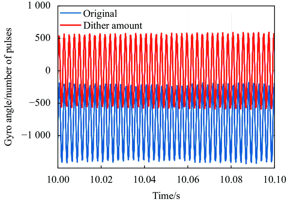
陀螺实测数据如图2所示,由此可以看出,陀螺输出脉冲中存在很强的抖动成分,在±500个脉冲内波动。

图 2 陀螺原始输出角度值与抖动量
Figure 2. Gyro original output angle value and dither amount
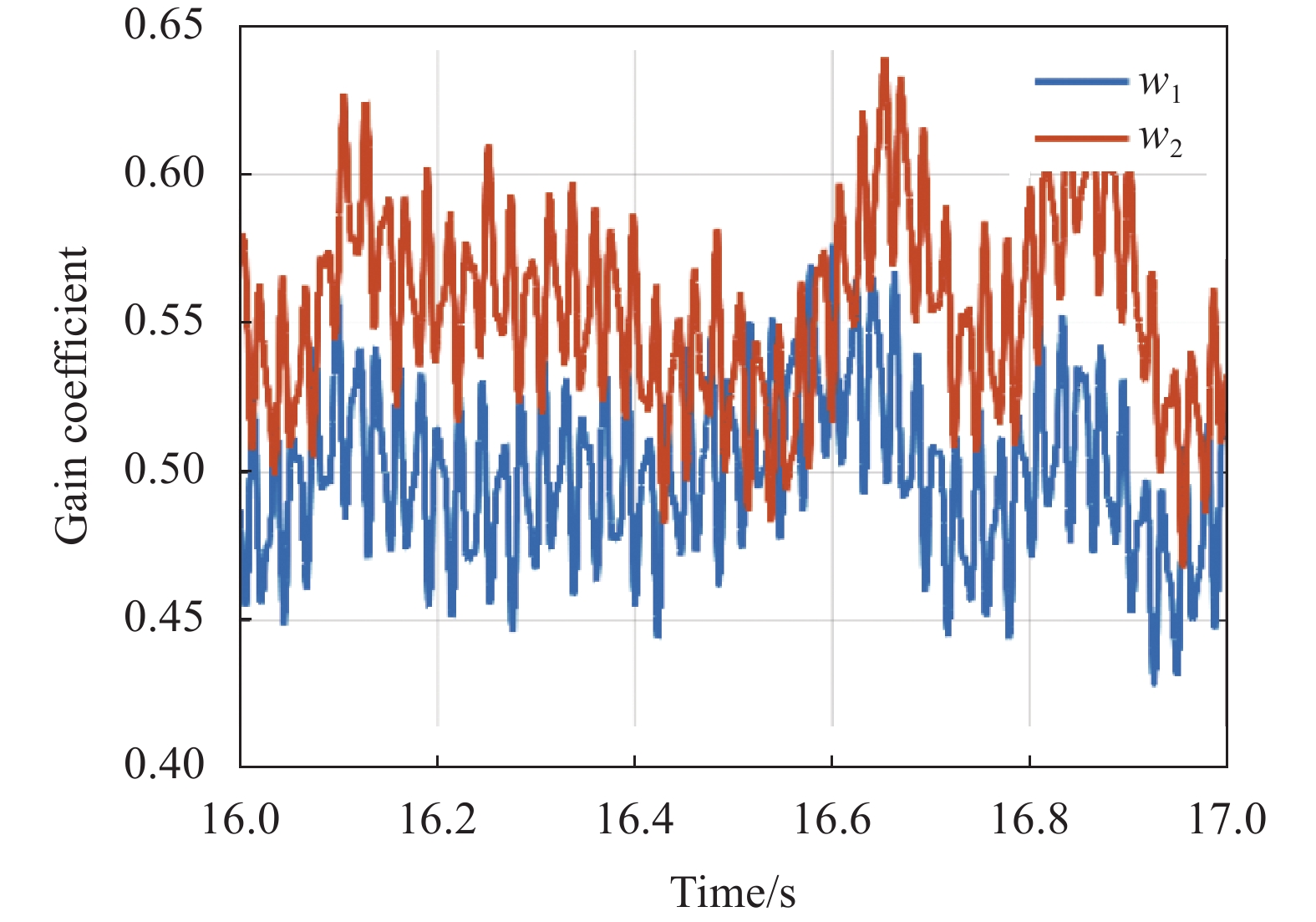
编程实现基于Kalman滤波算法的抖动剥除,经该程序计算得到的抖动剥除因子如图3所示,可见Kalman算法能够实时跟踪抖动剥除增益因子。

图 3 抖动剥除增益系数
Figure 3. Dither stripping gain coefficient
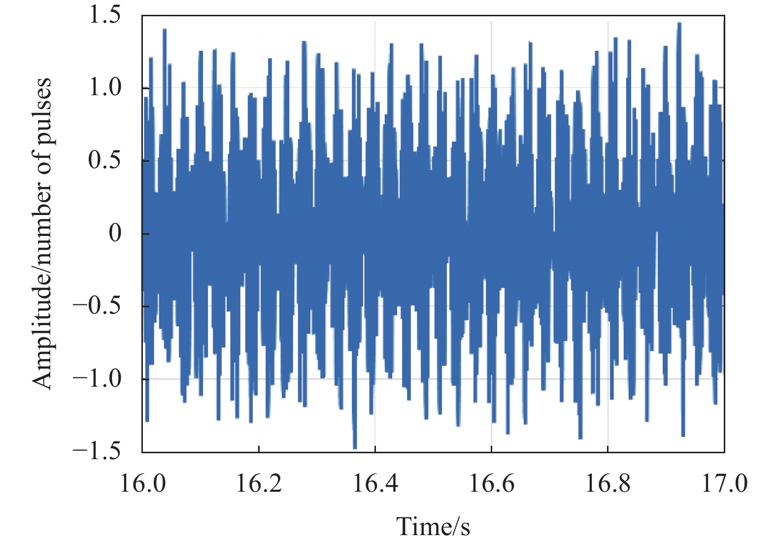
对陀螺输出角度值直接进行80阶FIR低通滤波得到的低通滤波值具有$ \dfrac{{N - 1}}{{2 fs}} = \dfrac{{80}}{{2 \times 4 \; 000}} = 10 \; {\rm{ms}} $的时延,将FIR低通滤波值前移40个数据即可得到理论上的实时低通滤波值,将基于Kalman滤波算法得到的抖动剥除结果与FIR实时低通滤波值比较可得抖动剥除误差如图4所示,可见抖动剥除误差在±1个脉冲内波动,该算法能够有效地去除FIR滤波10 ms延迟时间段内的抖动成分。对间隔40个子样的抖动剥除角度值作差可得10 ms累计角增量;对间隔40子样的FIR实时低通滤波值作差可得理论10 ms累计角增量,将二者进行对比即可得到10 ms累计角增量误差如图5所示,可见10 ms累计角增量误差在±2个脉冲内波动,对角度值进行滤波能有效减小抖动剥除误差积累。

图 4 抖动剥除误差
Figure 4. Dither stripping error
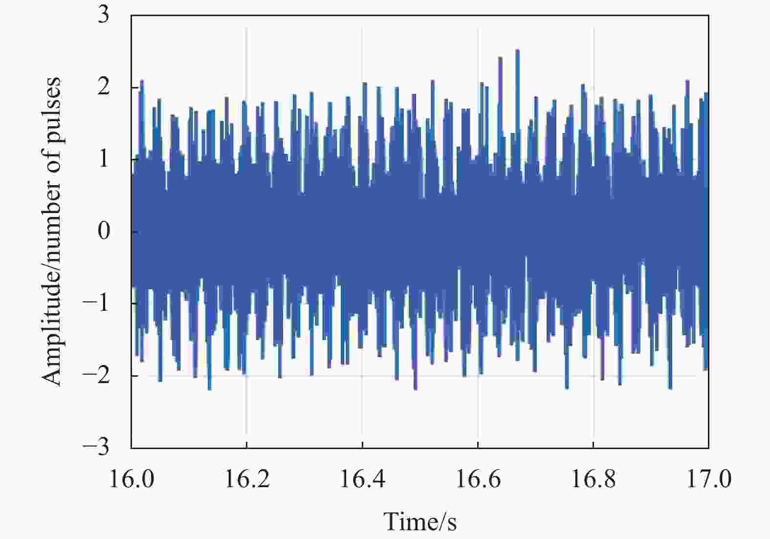
图 5 10 ms累计角增量误差
Figure 5. 10 ms cumulative angle increment error
转台转动过程中,基于Kalman滤波算法实现的抖动剥除结果与80阶FIR滤波器滤波结果对比如图6(a)所示,可以看出,文中提出的抖动剥除算法的去抖精度与80阶FIR滤波器相当,截取0.1 s内的抖动剥除与80阶FIR滤波器滤波结果对比图和对应的抖动剥除误差如图6(b)、(c)所示,可以看出抖动剥除结果相较于80阶FIR滤波仍有少量误差残留,但误差较小,在$ \pm $1脉冲左右,计算得到抖动剥除误差的标准差小于1脉冲,对应0.466″,故抖动剥除算法对延迟时间段的抖动解调精度优于0.5″,保证激光陀螺输出信号高精度解调的同时解决了FIR滤波带来的10 ms时延,实现了无延时的高精度测量。

图 6 (a)抖动剥除结果与80阶FIR滤波结果; (b)抖动剥除结果与80阶FIR滤波结果细节图;(c)抖动剥除误差细节图
Figure 6. (a) Dither stripping results and 80th-order FIR filtering results; (b) Dither stripping results and 80th-order FIR filtering results detail plot; (c) Detailed diagram of dither stripping error
-
文中基于相关抵消原理,针对激光陀螺惯导安装在雷达天线上随天线作大角度旋转的高动态环境下,提出了一种将FIR滤波和抖动剥除相结合的无延时测量方法,并基于90型激光陀螺进行了实验测试。实验结果表明:在转台转动过程中文中提出的抖动剥除算法对10 ms延迟时间段内抖动剥除精度优于0.5″,能够准确的测量延迟时间段内的姿态变化量,解决了FIR滤波带来的延迟问题,实现了无延迟测量,满足在高动态环境下的信号解调,拓宽了机械激光陀螺在快速跟踪场合的应用,可应用于激光陀螺高动态工作环境。
A non-delay measurement method for RLG based on the combination of FIR filtering and dither stripping
-
摘要: 对于雷达天线伺服跟踪这种高动态应用环境,传统的有限脉冲响应(Finite impulse response, FIR)低通滤波抖动解调引入的时间延迟会导致较大的跟踪误差。为了解决时间延迟问题,文中提出一种FIR滤波与抖动剥除相结合的测量方法,FIR实现具有时延的精确解调,抖动剥除对FIR延迟时间段进行精确补偿。抖动剥除基于相关抵消原理,通过Kalman滤波对陀螺抖动剥除增益因子进行动态跟踪,并对时延前后的抖动量进行实时计算。文中对无延时测量方法进行了激光陀螺实验测试,测试结果表明:该测量方法能够对FIR时延时间段的抖动量进行精确计算,抖动剥除精度优于0.5″,实现了陀螺无延迟测量。FIR滤波和抖动剥除相结合兼顾了激光陀螺的高精度和实时性,具有很好的应用前景。Abstract:
Objective The most often used technique to lessen the lock-in effect of a ring laser gyroscope (RLG) is mechanical dithering. However, the RLG output will maintain the dither rate which must be demodulated to obtain the true body rate. The integer period sampling method, high-frequency sampling filtering method, and dither stripping method are commonly used in RLG demodulation. For high dynamic tracking applications, since the sampling frequency is low, the integer period sampling method cannot meet the requirement of high bandwidth. Thus, the high-frequency sampling filtering method is applied. Due to the characteristic of a finite impulse response (FIR) filter, the high-frequency sampling filtering method inevitably introduces a time delay, which will result in significant tracking errors. Based on the correlation of signals, the dither stripping method can remove the dither signal in real-time through the correlation cancellation algorithm. In order to solve the problem that the time delay affects the accuracy of tracking in a highly dynamic environment, this paper proposes a demodulation scheme that combines FIR filtering with dither stripping. The dither stripping method is employed in the delay period of the FIR filtering so that the RLG demodulation can be zero-latency. Methods Aiming at the case that the RLG fitted on a radar antenna concurrently rotates, a non-delay measurement method based on the combination of FIR low-pass filtering and dither stripping is creatively proposed. To avoid the accumulation of stripping errors of angular increment during the time delay period, the dither stripping is directly carried out in the angle output of RLG. The angle output of RLG after bandpass filtering is taken as the dither feedback signal and the low-frequency angular acceleration is regarded as a random walk process. Based on the correlation between the dithering feedback signal and the dithering bias signal, the gain factor of dither stripping is dynamically tracked through Kalman filtering, and the amount of dither before and after delay is calculated in real-time. Results and Discussions The RLG experiment is conducted to verify the effectiveness of the proposed non-delay measurement method. The test results reveal that the dither stripping gain factor can be tracked through the Kalman filtering in real-time (Fig.3), and the dither stripping error varies within one pulse. The method can eliminate the dither component in a FIR filter delay period of 10 ms, where cumulative angle increment error is less than two pulses (Fig.4) and stripping in the angle output can effectively limit the accumulation errors (Fig.5). Compared to the 80-order FIR filter, the dither stripping accuracy has a negligible residual error of about one pulse, corresponding to 0.466′′, which achieves accurate demodulation without latency. Conclusions In order to achieve high accuracy of RLG demodulation in a highly dynamic environment, a non-delay measurement method is proposed in this paper. The combination of FIR filtering and dither stripping gives consideration to the characteristics of high-bandwidth and real-time performance, which eliminates the negative effect of time delay introduced by FIR filtering. The experiment results indicate that the accuracy of the proposed dither stripping method is better than 0.5″ during the delay period of 10 ms, which achieves zero-latency measurement. This paper provides a new demodulation scheme for RLGs applied in fast-tracking scenarios. -
Key words:
- ring laser gyroscope /
- FIR filtering /
- dither stripping /
- Kalman filter
-
[1] 贾将伟. 大仰角下激光陀螺惯导的误差建模与标定方法研究[D]. 长沙: 国防科技大学, 2019. Jia Jiangwei. Research on error modeling and calibration method of laser gyro strapdown inertial navigation system under the overturing[D]. Changsha: National University of Defense Technology, 2019. (in Chinses) [2] 张庆华. 高集成度激光陀螺小型化高压电源与抖动剥除技术的研究[D]. 长沙: 国防科学技术大学, 2010. Zhang Qinghua. Research on miniature high voltage power supply and dither stripper technology for compact ring laser gyros[D]. Changsha: National University of Defense Technology, 2010. (in Chinese) [3] 蔡刚刚, 谢元平, 王新. 一种优化的激光陀螺自适应抖动剥除算法. [J]. 半导体光电, 2012, 33(02):doi: 10.16818/j.issn1001-5868.2012.02.006 Cai Ganggang, Xie Yuanping, Wang Xin. An optimized algorithm for RLG adaptive dither stripping [J]. Semiconductor Optoelectronics, 2012, 33(2): 179. (in Chinese) doi: 10.16818/j.issn1001-5868.2012.02.006 [4] Doheny D, Kollig J. Dither stripper having least-mean-squares adaptive updating of dither stripper gains: US, 7440109B1 [P]. 2008-10-21. [5] Fritze K R, Killpatrick J E, Berndt D F. Ring laser gyro dither stripper: US, 5048963 [P]. 1991-09-17. [6] Killpatrick J. Dither stripper with non-linearity correction: US, 0201851 [P]. 2004-10-14. [7] Callaghan S P, Killpatrick J E. Dither signal remover for a dithered ring laser angular rate senser: US, 4826320[P]. 1989-05-02. [8] Ljung B, Schroeder G. Ring laser gyro dither pulse eliminator: US, 4344706[P]. 1982-08-17. [9] Banerjee K, Dam B, Majumdar K, et al. An improved dither-stripping scheme for strapdown ring laser gyroscopes[C]// Tencon IEEE Region 10 Conference, 2004: 689-692. [10] Widrow B, Glover J R, McCool J M, et al. Adaptive noise cancelling: principles and applications [J]. Proceedings of the IEEE, 1976, 63(12): 1692-1716. [11] 谢元平, 张广发. 抖动偏频激光陀螺抖动信号的自适应对消. [J]. 应用激光, 2000, 20(03): 121-123 doi: 10.3969/j.issn.1000-372X.2000.03.008 Xie Yuanping, Zhang Guangfa. Dither signal remover for a dithered ring laser gyroscope utilizing adaptive noise canceling. [J]. Applied Laser, 2000, 20(3): 121-123. (in Chinese) doi: 10.3969/j.issn.1000-372X.2000.03.008 [12] 张庆华, 胡绍民, 龙兴武. 应用自适应对消实现激光陀螺抖动信号的剥除[J]. 红外与激光工程, 2011, 40(03): 506-510. doi: 10.3969/j.issn.1007-2276.2011.03.026 Zhang Qinghua, Hu Shaomin, Long Xingwu. Dither signal removel of ring laser gyro based on adaptive noise canceling [J]. Infrared and Laser Engineering, 2011, 40(3): 506-510. (in Chinese) doi: 10.3969/j.issn.1007-2276.2011.03.026 [13] 张庆华, 樊振方. 基于RLS算法实现激光陀螺抖动信号剥除[J]. 激光技术, 2010, 34(05): 673-675. doi: 10.3969/j.issn.1001-3806.2010.05.026 Zhang Qinghua, Fan Zhenfang. Dither signal removal of ring laser gyro based on RLS [J]. Laser Technology, 2010, 34(5): 673-675. (in Chinese) doi: 10.3969/j.issn.1001-3806.2010.05.026 [14] 张庆华, 胡绍民, 卢广锋. 机械抖动激光陀螺新型信号处理方法的研究. 光学技术 [J]. 2010, 36(01):doi: 10.13741/j.cnki.11-1879/o4.2010.01.011 Zhang Qinghua, Hu Shaomin, Lu Guangfeng. Research on new signal processing method of mechanically dithered ring laser gyro [J]. Optical Technology, 2010, 36(1): 126-129. (in Chinese) doi: 10.13741/j.cnki.11-1879/o4.2010.01.011 [15] 张迪, 刘黎映, 陈军军, 等. 空间三轴激光陀螺高精度抖动剥除算法研究[J]. 导航定位与授时, 2022, 9(01):doi: 10.19306/j.cnki.2095-8110.2022.01.018 Zhang Di, Liu Liying, Chen Junjun, et al. Research on the high-precision dither stripping algorithm of orthogonal triaxial laser gyroscope [J]. Navigation Positioning & Timing, 2022, 9(1): 141-145. (in Chinese) doi: 10.19306/j.cnki.2095-8110.2022.01.018 [16] 洪腾腾, 胡绍林. Kalman滤波在导航中的应用研究[J]. 自动化博览, 2016(03): 72-75. doi: 10.3969/j.issn.1003-0492.2016.03.038 Hong Tengteng, Hu Shaolin. Applications of Kalman filter in the navigation [J]. Automation Panorama, 2016(3): 72-75. (in Chinese) doi: 10.3969/j.issn.1003-0492.2016.03.038 -

 点击查看大图
图(6)
计量
- 文章访问数: 92
- HTML全文浏览量: 14
- PDF下载量: 18
- 被引次数: 0

