


-
自测距雷达诞生以来,更远的探测距离和更高的探测精度始终是人们追求的目标,在这一目标的驱使下,研究者们不断优化雷达系统的信号拓扑结构。根据雷达方程,在雷达发射信号功率一定的前提下,为获得更远的探测距离和更高的探测精度,需要提高接收信号的信噪比[1-2]。
雷达接收机的作用是从带噪信号中将有用信号解调出来并进行处理,接收机的噪声抑制能力很大程度上决定了其性能。在雷达接收机设计中,镜像频率噪声抑制始终是一个关键环节。镜像频率噪声是在变频过程中引入的额外噪声,由于信号频率分量与镜像频率分量混频后均产生中频频率分量,导致解调信号与噪声在同一频率上相互叠加,致使该噪声无法通过滤波器滤除,最终导致雷达的微弱信号探测能力降低[3],因此需在变频前或变频过程中对镜像频率进行抑制[4]。在无线电超外差接收机中,目前常用的镜频抑制方法是在混频前将射频信号通过镜频抑制滤波器以滤除镜频分量,但当信号频率很高而中频很低时将给滤波器的设计带来困难。另一种方法是使用平衡式镜频抑制混频器,在混频中将镜频噪声抵消[5]。相干激光测距雷达接收机中同样存在镜频干扰的问题,目前相干激光雷达接收系统多采用将接收光信号与本振光直接在平衡探测器表面进行混频的方式[6],平衡探测能够增大中频信号幅值并抑制共模噪声,但难以对镜频噪声产生抑制[7]。
文中针对相干激光雷达远程测距,提出了一种针对线性调频信号的具有镜像频率抑制特性的下变频方法,该方法能够有效解决直接混频接收机的信噪比恶化问题。
-
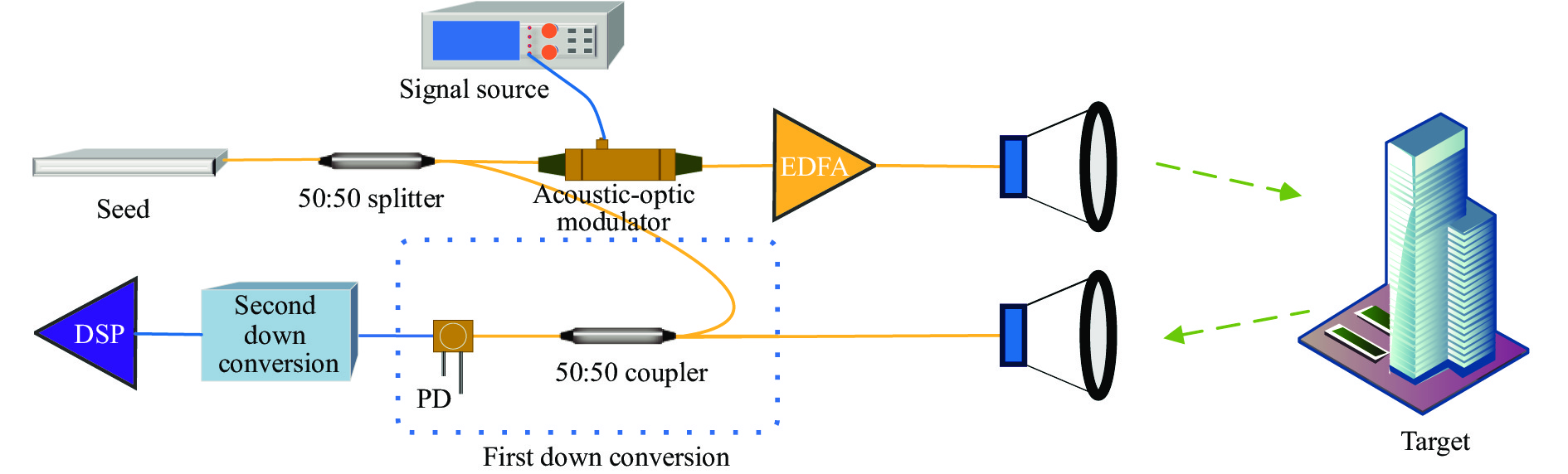
激光相干雷达系统如图1所示。目前激光雷达接收信号经光纤激光放大器后通常通过二次下变频对回波信号进行解调,其中首次下变频在光域进行,即将接收光信号与本振光混频得到中频电信号,经滤波后再通过二次混频将中频信号解调至基带,之后便可对基带信号进行脉冲压缩等处理,以获得距离、速度等信息[8]。
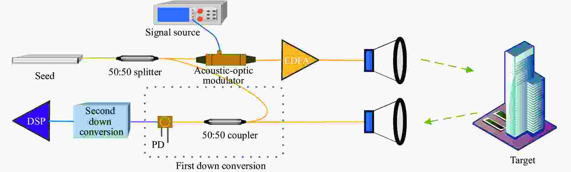
图 1 相干激光雷达工作流程图
Figure 1. Workflow diagram of laser coherent radar
目前,由中频信号下变频至基带信号通常使用模拟正交下变频或数字正交下变频,对其噪声抑制的研究已相对成熟[9],而在光域进行的光信号下变频多使用回波光信号与本振光直接混频的方式,这种方法使得镜频噪声与信号叠加,导致中频信号信噪比恶化,进而导致接收机整体性能降低,不利于对相对较弱的雷达回波信号进行探测和接收,因此需在混频前或混频中对镜像频率处的噪声进行抑制。
-
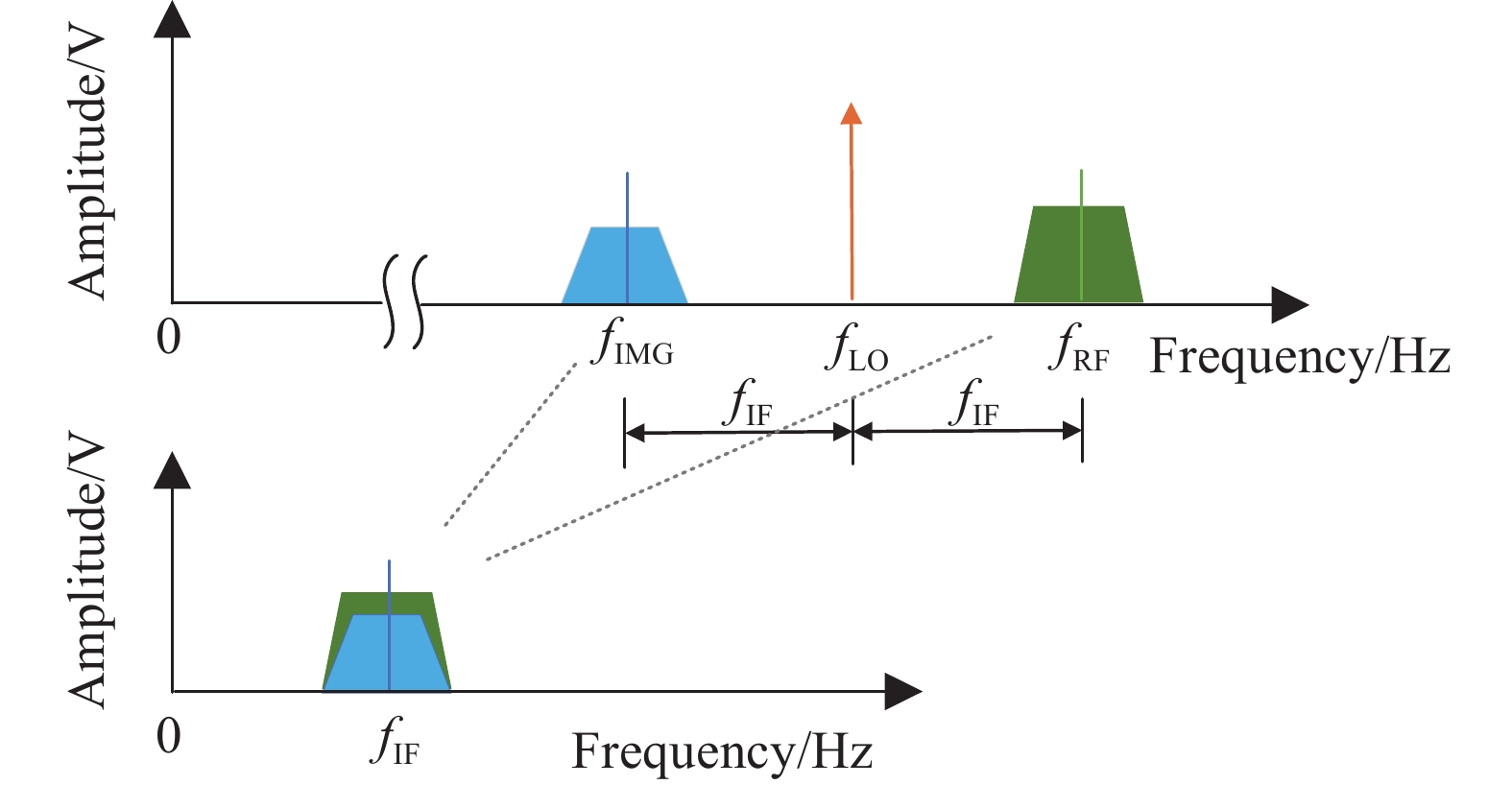
镜像频率指在雷达回波信号下变频过程中,回波信号与本振信号频率相差为一个中频频率,在本振频率另一侧,相距一个中频的频率成分在混频过程中将会与变频后的有用信号叠加导致解调信号信噪比降低[10],且由于混频后原信号中的有用信号与镜像频率处的噪声信号均被搬移至中频处,导致无法将有用信号与噪声分离[11],如图2所示。

图 2 镜像频率示意图
Figure 2. Schematic diagram of mirror frequency
由于相干激光雷达回波信号为光信号,激光雷达接收机通常采用二次下变频。其中第一次下变频在光域进行,同时实现下变频和光电转换,为消除镜像频率对有用信号的影响,引入正交下变频[12]。正交下变频将本振光信号分为幅度相等、相位相差90°的两束光,将两路信号光与两路本振光分别混频得到I支路信号和Q支路信号,如图3所示。其中,LO为幅度相等、相位相差90°的本振光,其频率与未调制载波频率相同[13]。
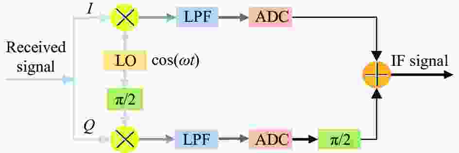
图 3 正交下变频结构图
Figure 3. Construction of quadrature frequency down conversion
设雷达回波信号为:
$$ s(t) = A\cos \left( {{\omega _{{\rm{RF}}}}t} \right) + B\cos \left( {{\omega _{{\rm{img}}}}t} \right) $$ (1) 式中:$ {\omega _{{\rm{RF}}}} $为有用信号角频率;${\omega _{{\rm{img}}}}$为镜像频率;A和B分别为有用信号和镜频信号的幅度。I支路本振信号为:
$$ {y_{{\rm{LO}}i}}(t) = \cos \left( {{\omega _{{\rm{LO}}}}t} \right) $$ (2) 含镜频的回波信号与本振信号混频得:
$$\begin{split} s(t) \cdot {y_{{\rm{LO}}i}}(t) = & \frac{A}{2}\left[ {\cos \left( {{\omega _{{\rm{RF}}}} + {\omega _{{\rm{LO}}}}} \right)t + \cos \left( {{\omega _{{\rm{RF}}}} - {\omega _{{\rm{LO}}}}} \right)t} \right] + \\ & \frac{B}{2}\left[ {\cos \left( {{\omega _{{\rm{img}}}} + {\omega _{{\rm{LO}}}}} \right)t + \cos \left( {{\omega _{{\rm{img}}}} - {\omega _{{\rm{LO}}}}} \right)t} \right] \end{split} $$ (3) 同时,借助光电探测器的光敏特性,混频后的和频分量由于频率大于光电探测器的测量范围而无法被转换为电信号,因此最终仅有中频信号和噪声被转换为电信号,即
$$ {y_{{\rm{OUT}}i}}(t) = \frac{A}{2}\left[ {\cos \left( {{\omega _{{\rm{RF}}}} - {\omega _{{\rm{LO}}}}} \right)t} \right] + \frac{B}{2}\left[ {\cos \left( {{\omega _{{\rm{img}}}} + {\omega _{{\rm{LO}}}}} \right)t} \right] $$ (4) Q支路本振信号为:
$$ {y_{{\rm{LO}}}}(t) = \sin ({\omega _{{\rm{LO}}}}t) $$ (5) 经光电转换后可得:
$$ {y_{{\rm{OUT}}q}}(t) = - \frac{A}{2}\left[ {\sin \left( {{\omega _{{\rm{RF}}}} - {\omega _{{\rm{LO}}}}} \right)t} \right] + \frac{B}{2}\left[ {\sin \left( {{\omega _{{\rm{img}}}} + {\omega _{{\rm{LO}}}}} \right)t} \right] $$ (6) 将Q支路信号移相90°得:
$$ y{'_{{\rm{OUT}}q}}(t) = \frac{A}{2}\left[ {\cos \left( {{\omega _{{\rm{RF}}}} - {\omega _{{\rm{LO}}}}} \right)t} \right] - \frac{B}{2}\left[ {\cos \left( {{\omega _{{\rm{img}}}} + {\omega _{{\rm{LO}}}}} \right)t} \right] $$ (7) 将I支路与移相后的Q支路信号相加得:
$$ \begin{split} {y_{{\rm{OUT}}}}(t) = & {y_{{\rm{OUT}}i}}(t) + y{'_{{\rm{OUT}}q}}(t) = \\& A\left[ {\cos \left( {{\omega _{{\rm{RF}}}} - {\omega _{{\rm{LO}}}}} \right)t} \right] = A\cos {\omega _{{\rm{IF}}}}t \end{split}$$ (8) 式中:$ {\omega }_{{\rm{IF}}} $为下变频后得到的中频频率,镜频干扰由此得以消除[14]。Q支路信号的90°相移可通过Hilbert滤波器实现[15],其系统函数为:
$$ h(t) = \frac{1}{{\pi t}} $$ (9) -
在1.2节的讨论中,I/Q解调要求本振信号相位差保持严格的90°,I/Q支路振幅保持相等,才能实现对镜频的完全抑制,幅度相位的不平衡将导致镜频抑制效果降低,在实际的I/Q调制与解调过程中,由于器件的非理想化、电路设计的差异、光纤长度的误差等都可能会带来幅度相位不平衡问题。因此,需对解调信号进行补偿以降低I/Q支路不平衡造成的影响。目前对I/Q不平衡的修正方法主要有数字补偿法、FIR滤波器补偿法和自适应相位分集法等[16-17],文中使用数字补偿法对幅度相位不平衡进行补偿。
设存在幅相不平衡的支路信号分别为:
$$ I = A\cos (\theta ) $$ (10) $$ Q = (1 + \varepsilon )A\cos (\theta + \phi ) $$ (11) 式中:$ \varepsilon $为幅度误差;$ \phi $为相位误差。设期望信号为$ I' = A\cos (\theta ) $,$ Q' = A\sin (\theta ) $,可以建立$ IQ $和$ I'Q' $之间的关系:
$$\begin{split} \left[ {\begin{array}{*{20}{l}} {{I^\prime }} \\ {{Q^\prime }} \end{array}} \right] = & \left[ {\begin{array}{*{20}{l}} {A\cos \theta } \\ {A\sin \theta } \end{array}} \right] = \left[ {\begin{array}{*{20}{l}} {{a_{11}}}&{{a_{12}}} \\ {{a_{21}}}&{{a_{22}}} \end{array}} \right] \cdot \left[ {\begin{array}{*{20}{l}} I \\ Q \end{array}} \right] = \\& \left[ {\begin{array}{*{20}{l}} {{a_{11}}}&{{a_{12}}} \\ {{a_{21}}}&{{a_{22}}} \end{array}} \right] \cdot \left[ {\begin{array}{*{20}{c}} {A\cos (\theta )} \\ {(1 + \varepsilon )A\sin (\theta - \phi )} \end{array}} \right] \end{split}$$ (12) 求解可得$ {a_{21}} = \tan \phi $,$ {a_{22}} = \dfrac{1}{{(1 + \varepsilon )\cos (\phi )}} $。令 $ P = \left[ {\begin{array}{*{20}{c}} 1&0 \\ {\tan \phi }&{\dfrac{1}{{(1 + \varepsilon )\cos (\phi )}}} \end{array}} \right] $。
对幅度和相位误差进行估计:
$$ \hat \varepsilon = \sqrt {\frac{{E\left\{ {{Q^2}(n)} \right\}}}{{E\left\{ {{I^2}(n)} \right\}}}} - 1 $$ (13) $$ \hat \phi = - \arcsin \frac{{E\{ I(n)Q(n)\} }}{{\sqrt {E\left\{ {{I^2}(n)} \right\}E\left\{ {{Q^2}(n)} \right\}} }} $$ (14) 式中:$ \hat \varepsilon $和$ \hat \phi $分别为幅度误差和相位误差的估计量。由此可构造出矩阵P,从而对幅度相位进行补偿。
-
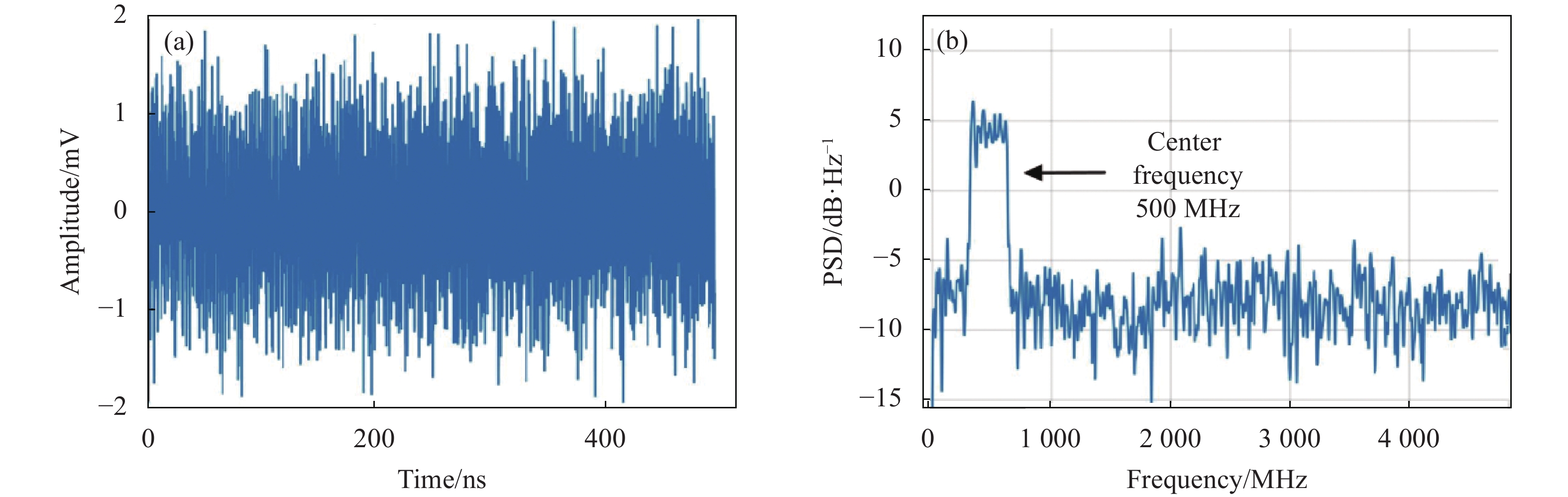
仿真中使用193 GHz的正弦信号作为载波,将频率为300~700 MHz的LFM信号作为调制信号,产生脉宽500 ns的原始信号,将该信号叠加高斯噪声模拟雷达回波信号,验证光域正交解调对镜像频率噪声的抑制性能,使用仿真软件分析该方案的可行性。当模拟雷达回波信号信噪比为−20 dB时,其时域和频域波形如图4(a)和图4(b)所示。

图 4 (a) 雷达回波信号时域图;(b) 雷达回波信号功率谱密度图
Figure 4. (a) Time domain diagram of radar echo signal; (b) PSD diagram of radar echo signal
-
在不存在幅度和相位不平衡条件下进行仿真,使用直接混频法对该信号进行混频,将信号频谱的中心频率搬移至500 MHz,以模拟回波信号从光信号中被剥离的过程,将混频结果通过截止带宽为10 GHz的数字滤波器以模拟光电转换模块能够接收的最大带宽,混频结果的时域波形如图5(a)所示,对应的频域图如图5(b)所示。
使用正交混频法对雷达回波信号下变频,并分别对I支路信号与Q支路信号以10 Gsps采样率进行抽取。为实现Q支路的90°相移并进一步抑制噪声,构造离散信号的Hilbert滤波器,为兼顾滤波效果和可实现性,滤波器采用FIR型,阶数为60,通带为200~800 MHz,其幅频响应曲线和相频响应曲线如图6所示。

图 5 (a) 直接混频法混频结果时域图;(b) 直接混频法混频结果功率谱密度图
Figure 5. (a) Time domain diagram of mixing results of direct mixing method; (b) PSD diagram of mixing results of direct mixing method
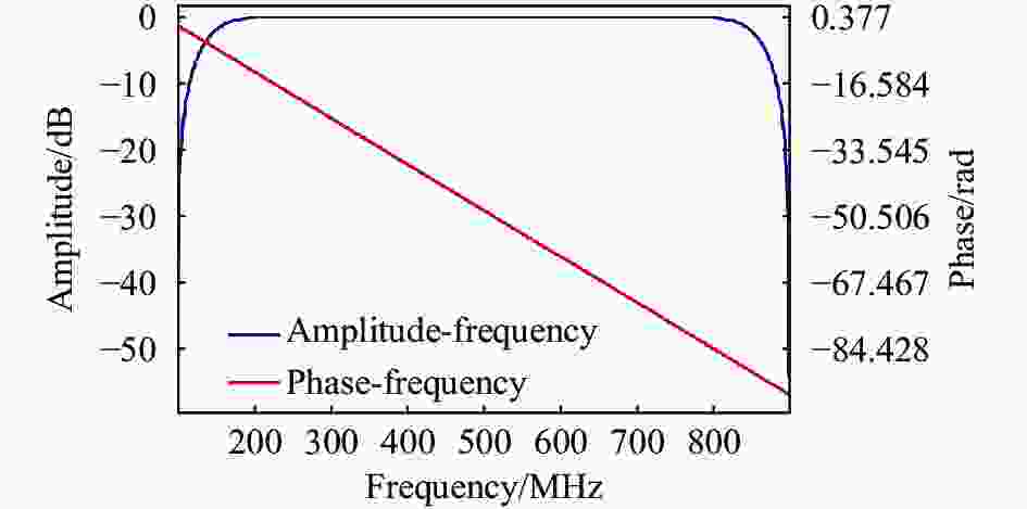
图 6 Hilbert滤波器幅频响应曲线和相频响应曲线
Figure 6. Amplitude-frequency response and phase-frequency response curve of Hilbert filter
将Q支路信号接入上述滤波器,将滤波器输出结果与I支路信号相加得到正交混频结果,混频结果的时域波形如图7(a)所示,对应的频域图如图7(b)所示。

图 7 (a) 正交混频法混频结果时域图;(b) 正交混频法混频结果功率谱密度图
Figure 7. (a) Time domain diagram of mixing results of orthogonal mixing method; (b) PSD diagram of mixing results of orthogonal mixing method
经仿真分析,将模拟雷达回波信号分别使用两种方法进行初次下变频,随后使用相同的数字正交下变频进行二次下变频以得到复基带信号。使用直接混频和正交混频所得到的基带信号信噪比及使用正交混频带来的信噪比增益如图8所示,仿真结果表明,在接收信号信噪比为−20 dB、采样率为10 Gsps时,相较于直接混频法,正交混频法得到的解调结果信噪比提高了3 dB左右。
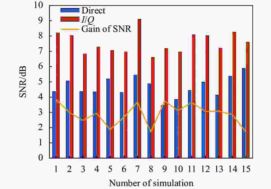
图 8 不同混频方式下仿真结果信噪比对比图
Figure 8. Diagram of comparison of SNR of simulation results under different mixing methods
-
在存在I/Q支路幅度相位不平衡时进行仿真,将Q支路作为存在幅度和相位误差的支路,A为幅度误差,$ \phi $为相位误差,取A=+0.5,$ \phi = \pi /10 $。由公式(13)和公式(14)可知,幅相误差补偿效果与信号采样点数成正相关,取脉宽500 ns、10 Gsps采样率进行仿真。为便于观察,将补偿前后的解调结果分别作为复信号的实部和虚部进行绘图,根据1.2节,当不存在幅度相位不平衡时,上述复信号在解调信号频率处应为单边带信号,补偿前频谱图如图9(a)所示,补偿后频谱图如图9(b)所示。

图 9 (a) I/Q支路不平衡补偿前功率谱密度图;(b) I/Q支路不平衡补偿后功率谱密度图
Figure 9. (a) PSD diagram before compensating for I/Q branch imbalance; (b) PSD diagram after compensating for I/Q branch imbalance
补偿前由于Q支路幅度和相位的偏移导致镜像频率处的噪声被搬移至基带,在信号频率处产生了双边带噪声,而补偿后镜像频率干扰消失,补偿前后解调信号信噪比上升0.07 dB。取不同幅度不平衡值进行仿真,当接收信号信噪比为−15 dB,相位误差为0时仿真结果如表1所示,在采样点数固定、幅度不平衡较大时,补偿后仍能达到较高的信噪比。
表 1 幅度误差补偿前后信噪比数据
Table 1. Data of signal to noise ratio before and after amplitude error compensation
SNR Amplitude error/mV −0.3 0.2 0.5 2 5 SNR before compensation/dB 4.69 4.79 4.67 3.89 3.08 SNR after compensation/dB 4.82 4.82 4.82 4.82 4.82 Gain of SNR/dB 0.13 0.02 0.15 0.92 1.73 幅度相等而相位产生不平衡时,补偿前后的信噪比数据如表2所示,当载波的幅度不平衡误差在$ \pi /2 $以内,接收信号信噪比为−15 dB时,相位补偿均能够产生较好的处理结果。综上,当幅度和相位误差在一定范围内时,经数字补偿的解调信号信噪比基本达到幅度和相位平衡时的水平。
表 2 相位误差补偿前后信噪比数据表
Table 2. Data table of signal to noise ratio before and after phase error compensation
SNR Phase error/rad ${\pi }/{2}$ ${\pi }/{3}$ ${\pi }/{5}$ ${\pi }/{10}$ ${\pi }/{50}$ SNR before compensation/dB 0.12 3.51 4.33 4.65 4.71 SNR after compensation/dB 0.12 4.71 4.71 4.71 4.74 Gain of SNR/dB 0 1.21 0.39 0.07 0.03 -
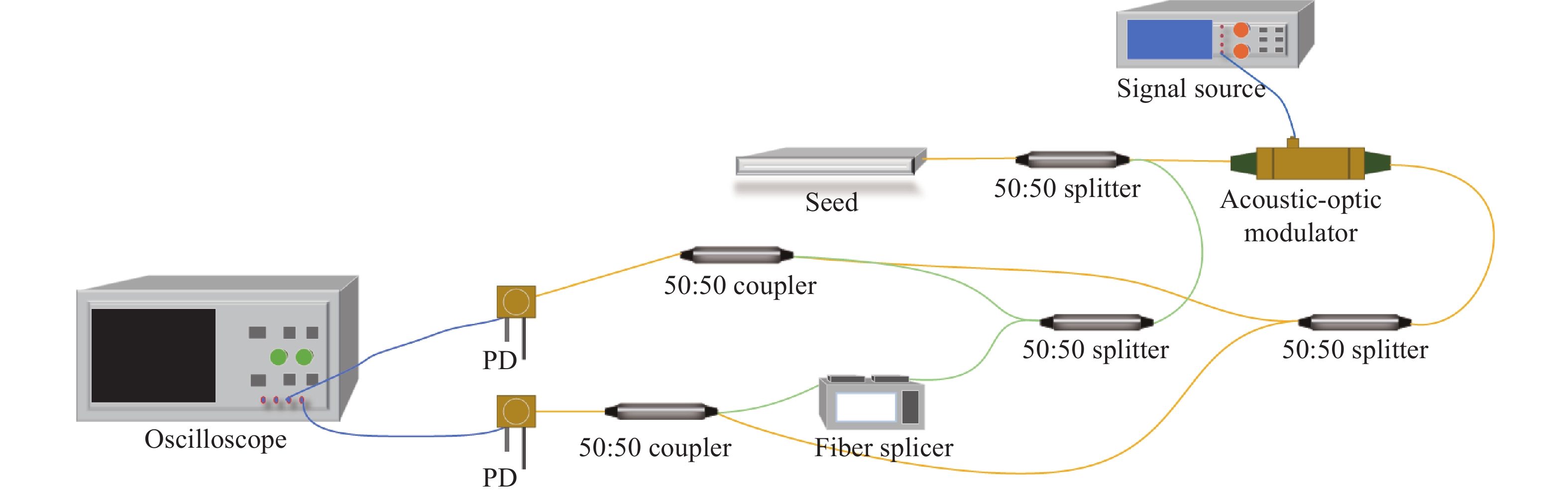
首先搭建用于传输本振光并使两路本振光相位相差90°的本振光通路。将连续光种子源进行正弦波调制并进行50:50分束,使其通过本振光通路,将本振光通路接入高精度光纤熔接机,在本振通路输出端与未调制载波混频以观察其相位,通过控制光程差使两本振通道间产生约90°的相位差,光路图如图10所示。
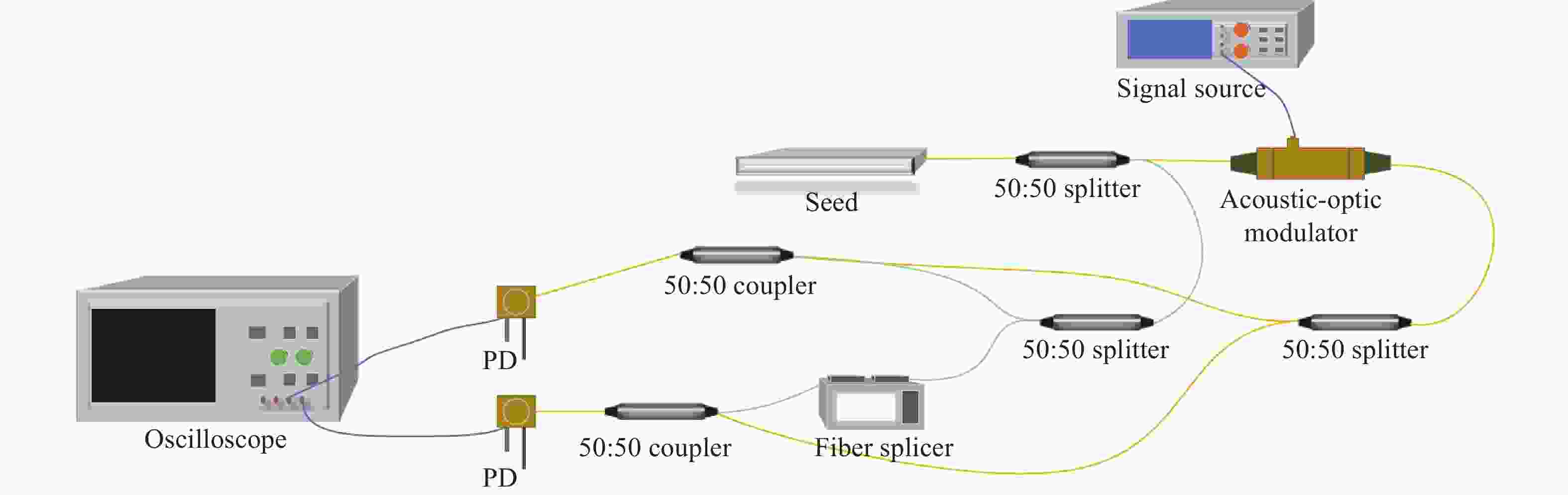
图 10 LO通道间产生90°相位差光纤示意图
Figure 10. Diagram of fiber producing 90° phase difference between the LO channels
使用上述本振光通路进行实验,采用的连续光种子源中心波长为1550.129 nm,使用的电光衰减器可将输入信号功率光衰减至−50 dBm,经实测得到光衰减器损耗为0.3 dB。采用两路ADC同时对中频信号进行采样,ADC速率为10 Gsps。
实验中,将连续光种子源经50:50分束器分为两束相干光,其中一路接入上述本振光通路,另一路接入调制器进行斩波和调制,已调信号脉宽为500 ns,调制信号为频率为300~700 MHz的chirp信号,将该已调信号接入延时光纤作为雷达回波信号。将回波信号经50:50分束器分为两路并分别与两本振光在光电探测器表面进行混频,对两路混频信号同时进行ADC采样,最后对采样信号进行分析处理。
对下变频信号进行采集分析,其时域波形如图11所示,由于I支路的混频结果等同于传统的直接混频法,故将I支路混频结果作为使用直接混频法得到的解调结果进行对比分析。其信噪比为0.08 dB,使用I/Q混频方式在未经幅度相位不平衡补偿时得到的解调信号信噪比为2.33 dB,此时两支路平均相位不平衡量为20.91°,归一化后的平均幅度不平衡量为0.0013。采用1.3节中的方法对I/Q解调信号进行幅度相位不平衡补偿后,其信噪比达到3.03 dB,相较于直接混频法提升了约2.95 dB。

图 11 混频后I/Q信号图
Figure 11. Diagram of mixed I/Q signal
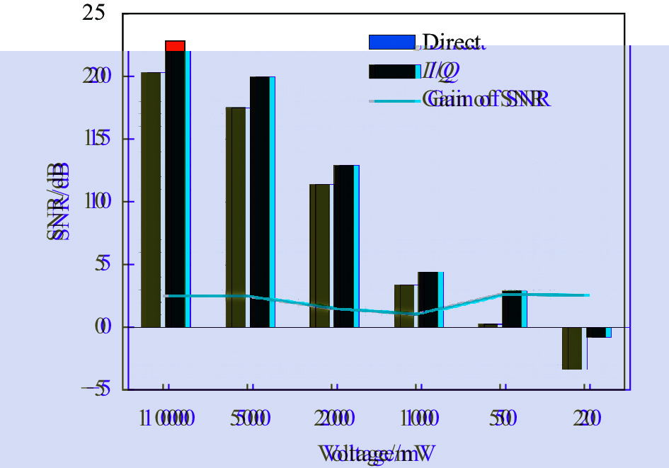
使用不同信噪比的回波信号进行分析,回波信号信噪比随实验次数逐次降低,解调信号信噪比如图12所示,接收信号的信噪比反映为解调后时域信号的电平值大小,电平值越大则接收到的回波信号信噪比越高。结果表明,在一定的信噪比范围内,相较于直接混频的方式,正交下变频对于不同质量的雷达回波信号均能够产生3 dB左右的信噪比增益。

图 12 不同信噪比接收信号解调后信噪比及信噪比增益对比图
Figure 12. Diagram of SNR and SNR gain of demodulated signals of received signals with different SNR
-
文中以相干激光雷达远程测距为背景,对接收机下变频系统进行优化,提出了一种有效提高解调信号信噪比的下变频方案。该方案采用光电联合正交下变频的方式进行信号解调,通过使用正交混频,有效抑制了镜像频率噪声的干扰,通过I/Q支路幅度和相位不平衡量的补偿算法进一步提升了I/Q支路的正交性,从而提升了对镜像频率的抑制效果。根据仿真和实验验证,在其他条件不变时,使用该方案得到的解调信号信噪比相比于传统接收机混频方式提高了约3 dB。
Optoelectronic dual down-conversion technology in laser coherent radar
-
摘要: 在激光雷达远程测距中,雷达接收机需要在接收信号信噪比较低的背景下,对其中的有用信号进行识别、提取和判决。因此,为保证雷达系统的探测距离和精度,在激光发射功率一定的前提下,需在信号接收处理的各环节中设法提高信号的信噪比。当前外差式激光雷达接收机在变频时将本振光和信号光直接混频,导致镜像频率噪声与有用信号叠加,致使解调信噪比恶化。针对激光雷达接收机提高信号信噪比的需求,提出了一种在信号解调过程中对镜频干扰进行抑制,从而提高解调信噪比的方法。采用光电联合I/Q下变频,首先参考Hartley结构,在光信号的解调过程中对镜频处的噪声进行抵消,随后采用I/Q支路不平衡补偿算法对潜在的双支路不平衡量进行矫正,最后使用数字正交下变频将中频信号解调至基带。仿真和实验表明,该方法能够有效消除调频信号变频过程中引入的镜像频率噪声,相较于传统激光相干雷达接收机方案,该方案解调得到的基带信号信噪比提升了约3 dB。Abstract:
Objective In lidar remote ranging, the lidar receiver needs to extract weak signals from noisy received signals. The detection ability of the lidar receiver for weak signals is an important part of ensuring the detection distance and accuracy of the lidar system. Improving the signal-to-noise ratio (SNR) of the demodulated signal can effectively improve the detection distance and accuracy of lidar. Under the premise of a certain laser transmission power, it is necessary to improve the SNR during the reception process. Traditional heterodyne lidar receivers typically down-convert the lidar echo signal to the baseband through two down-conversions. The first down-conversion directly mixes the echo light signal with the local oscillator light, which introduces additional mirror frequency noise. Due to the mirror frequency noise being the same as the useful signal frequency after demodulation, the noise cannot be eliminated through a filter after demodulation, resulting in a deterioration of the SNR of the demodulated signal. In contrast, using orthogonal demodulation can suppress the elimination of mirror frequency noise through the phase relationship between the two branches during the demodulation process, thereby improving the SNR of the demodulated signal. In practical applications, affected by the non-ideal state of the device, the two branches in the quadrature demodulation structure may not be able to achieve a fully balanced state. Therefore, the algorithm compensation for the orthogonality of the two branch signals is also worth in-depth study. The use of appropriate mirror frequency suppression down-conversion structures and the use of relevant algorithms for imbalance compensation is expected to improve the detection performance of lidar systems. Methods Based on the principle of receiving and demodulating echo signals in a lidar system, and referring to structures such as Hartley and Weaver, an orthogonal down-conversion structure for optical signals in the receiver was constructed. At the same time, based on the statistical characteristics of the orthogonal signal, a compensation algorithm is used to compensate for the error of the demodulated quasi orthogonal signal to ensure that the mirror frequency noise is completely eliminated. Subsequently, the demodulated intermediate frequency signal is subjected to secondary down-conversion to obtain the baseband signal. Finally, by computing the SNR of two schemes can effectively determine the performance of suppression of the mirror frequency. Results and Discussions Simulation analysis and experimental verification show that the SNR using the biorthogonal demodulation scheme is superior to traditional heterodyne demodulation schemes. In addition, when there is amplitude or phase imbalance in the orthogonal structure, the use of correlation compensation algorithms can effectively eliminate the additional noise interference generated by this imbalance (Fig.9), further improving the SNR of the modulated signal. The results show that compared to traditional heterodyne lidar receivers, the SNR of the demodulated signal processed by this scheme is improved by about 3 dB (Fig.12). Conclusions This study is based on the background of coherent lidar remote ranging, and improves the down-conversion structure of the lidar receiver. By adopting an optoelectronic dual orthogonal down-conversion method, it effectively suppresses mirror frequency noise, improves the SNR of the demodulated signal, and ultimately improves the lidar detection distance and detection accuracy. Due to the fact that the I/Q imbalance compensation algorithm used in this scheme is based on the statistical characteristics of the signal, which relies on the length of the sampled signal and the integrity of its period, its compensation performance is not stable for different sampling signals. Therefore, researching more advanced compensation algorithms can achieve better mirror frequency suppression effect. Finally, this scheme only suppresses mirror frequency interference in frequency mixing, and in reality, there is also frequency related noise. The suppression of frequency related noise can further improve the effectiveness of signal noise control. -
图 4 (a) 雷达回波信号时域图;(b) 雷达回波信号功率谱密度图
Figure 4. (a) Time domain diagram of radar echo signal; (b) PSD diagram of radar echo signal
图 5 (a) 直接混频法混频结果时域图;(b) 直接混频法混频结果功率谱密度图
Figure 5. (a) Time domain diagram of mixing results of direct mixing method; (b) PSD diagram of mixing results of direct mixing method
图 6 Hilbert滤波器幅频响应曲线和相频响应曲线
Figure 6. Amplitude-frequency response and phase-frequency response curve of Hilbert filter
图 7 (a) 正交混频法混频结果时域图;(b) 正交混频法混频结果功率谱密度图
Figure 7. (a) Time domain diagram of mixing results of orthogonal mixing method; (b) PSD diagram of mixing results of orthogonal mixing method
图 8 不同混频方式下仿真结果信噪比对比图
Figure 8. Diagram of comparison of SNR of simulation results under different mixing methods
图 9 (a) I/Q支路不平衡补偿前功率谱密度图;(b) I/Q支路不平衡补偿后功率谱密度图
Figure 9. (a) PSD diagram before compensating for I/Q branch imbalance; (b) PSD diagram after compensating for I/Q branch imbalance
图 10 LO通道间产生90°相位差光纤示意图
Figure 10. Diagram of fiber producing 90° phase difference between the LO channels
图 12 不同信噪比接收信号解调后信噪比及信噪比增益对比图
Figure 12. Diagram of SNR and SNR gain of demodulated signals of received signals with different SNR
表 1 幅度误差补偿前后信噪比数据
Table 1. Data of signal to noise ratio before and after amplitude error compensation
SNR Amplitude error/mV −0.3 0.2 0.5 2 5 SNR before compensation/dB 4.69 4.79 4.67 3.89 3.08 SNR after compensation/dB 4.82 4.82 4.82 4.82 4.82 Gain of SNR/dB 0.13 0.02 0.15 0.92 1.73  下载: 导出CSV
表 2 相位误差补偿前后信噪比数据表
Table 2. Data table of signal to noise ratio before and after phase error compensation
SNR Phase error/rad ${\pi }/{2}$ ${\pi }/{3}$ ${\pi }/{5}$ ${\pi }/{10}$ ${\pi }/{50}$ SNR before compensation/dB 0.12 3.51 4.33 4.65 4.71 SNR after compensation/dB 0.12 4.71 4.71 4.71 4.74 Gain of SNR/dB 0 1.21 0.39 0.07 0.03
下载: 导出CSV
-
[1] Mehendale N, Neoge S. Review on lidar technology [J]. SSRN Electronic Journal, 2020: 3604309. [2] 张笑宇, 王凤香, 郭颖, 等. 基于InGaAs单光子探测器的线阵扫描激光雷达及其光子信号处理技术研究[J]. 红外与激光工程, 2023, 52(3): 20220474. Zhang Xiaoyu, Wang Fengxiang, Guo Ying, et al. Research on linear array scanning lidar and photon signal processing technology based on InGaAs single-photon detector [J]. Infrared and Laser Engineering, 2023, 52(3): 20220474. (in Chinese) [3] Torun R, Bayer M M, Zaman I U, et al. Realization of multitone continuous wave LiDAR [J]. IEEE Photonics Journal, 2019, 11(4): 1-10. [4] Zhu D, Chen W, Pan S. Photonics-enabled balanced Hartley architecture for broadband image-reject microwave mixing [J]. Optics Express, 2018, 26(21): 28022-28029. [5] 郭凡玉, 唐宗熙, 赵世巍. 20 GHz镜频抑制谐波混频器[J]. 半导体技术, 2011, 11: 866-870. Guo Fanyu, Tang Zongxi, Zhao Shiwei. 20 GHz image rejection harmonic mixer [J]. Semiconductor Technology, 2011, 36(11): 866-870. (in Chinese) [6] 吴聪. 自由空间光通信高灵敏度平衡探测器特性的研究[D]. 成都: 电子科技大学, 2022. Wu Cong. Research on the characteristics of high sensitivity balanced detector in free space optical communication[D]. Chengdu: University of Electronic Science and Technology of China, 2022. (in Chinese) [7] 陈玉宝, 步志超, 王振会. 基于镜频抑制零差探测的全光纤测风激光雷达系统[J]. 北京理工大学学报, 2018, 38(02): 205-210. Chen Yubao, Bu Zhichao, Wang Zhenhui. A Doppler wind lidar based on image-reject homodyne technology [J]. Transactions of Beijing Institute of Technology, 2018, 38(2): 205-210. (in Chinese) [8] Stretch V, Wixted J T. On the difference between strength-based and frequency-based mirror effects in recognition memory [J]. Journal of Experimental Psychology: Learning, Memory, and Cognition, 1998, 24(6): 1379. doi: 10.1037/0278-7393.24.6.1379 [9] 梅理, 崇毓华, 朱宇鹏, 等. 基于可调光延迟线的微波光子零中频接收机研究[J]. 中国激光, 2021, 48(9): 0906001. doi: 10.3788/CJL202148.0906001 Mei Li, Chong Yuhua, Zhu Yupeng, et al. Optical delay line-based microwave photonic zero-intermediate-frequency receiver [J]. Chinese Journal of Lasers, 2021, 48(9): 0906001. (in Chinese) doi: 10.3788/CJL202148.0906001 [10] 丁鹭飞, 耿富录, 陈建春. 雷达原理[M]. 第四版. 北京: 电子工业出版社, 2009. [11] 刘锡民, 张建华, 杨德钊, 等. 相干激光引信综述(特邀)[J]. 红外与激光工程, 2018, 47(3): 303001-0303001(6). doi: 10.3788/IRLA201847.0303001 Liu Ximin, Zhang Jianhua, Yang Dezhao, et al. Review on coherent laser fuze (Invited) [J]. Infrared and Laser Engineering, 2018, 47(3): 0303001. (in Chinese) doi: 10.3788/IRLA201847.0303001 [12] Stockill R, Forsch M, Hijazi F, et al. Ultra-low-noise microwave to optics conversion in gallium phosphide [J]. Nature Communications, 2022, 13(1): 6583. doi: 10.1038/s41467-022-34338-x [13] 谢威. 基于微波光子学的变频系统研究[D]. 南宁: 广西大学, 2022. Xie Wei. Frequency down-conversion system based on microwave photonics [D]. Nanning: Guangxi University, 2022. (in Chinese) [14] Yan Lei. Quadrature mixer and digital demodulation laser ranging system [D]. Taiyuan: North University of China, 2013. (in Chinese) [15] 戴健, 李斌, 王征炬, 等. 一种宽带数字信道化接收及发射系统[J]. 电子信息对抗技术, 2022, 37(04): 13-16, 47. Dai Jian, Li Bin, Wang Zhengju, et al. A wide-band digital channelization receiver and transmitter system [J]. Electronic Information Warfare Technology, 2022, 37(4): 13-16, 47. (in Chinese) [16] He Y, Zhou X, Huo J, et al. IQ imbalance compensation based on simplified GSOP and FPGA implementation in optical coherent QPSK receiver [J]. Optical Fiber Technology, 2020, 56: 102206. [17] 姚亚峰, 陈怡铭, 周群群, 等. 改进的统计特性IQ不平衡矫正算法[J]. 华中科技大学学报(自然科学版), 2021, 49(11): 12-16. doi: 10.13245/j.hust.211103 Yao Yafeng, Chen Yiming, Zhou Qunqun, et al. Improved IQ imbalance correction algorithm based on statistical characteristics [J]. Journal of Huazhong University of Science and Technology (Natural Science Edition), 2021, 49(11): 12-16. (in Chinese) doi: 10.13245/j.hust.211103 -

 点击查看大图
计量
- 文章访问数: 78
- HTML全文浏览量: 6
- PDF下载量: 33
- 被引次数: 0

