


 下载:
下载:


-
中红外激光处于大气窗口波段,同时又是众多原子及分子的吸收峰,因此在光谱学、医学、通信、遥 感、环境监测及红外对抗领域有着广泛而重要的应用前景[1]。光参量振荡器 (Optical Parametric Oscillator, OPO) 可将成熟的近红外或可见激光转换为中远红外激光,该技术手段结构简单,可实现全固化、小型化,并且其稳定性高,是一种具有广泛应用前景的中红外激光产生方式[2]。
在中红外OPO中,在非线性晶体和OPO腔镜的共同作用下,泵浦光向信号光和闲频光转换。但当泵浦光能量较强时,产生的信号光和闲频光也较强,此时会发生信号光和闲频光向泵浦光转化的逆转换过程,该过程会严重影响OPO的转换效率。此外,由于逆转换还容易损伤非线性晶体或晶体和OPO腔的膜层。如何抑制OPO腔中的逆转换并提高大能量泵浦条件下的OPO转换效率一直是科研人员关注的焦点。
2011年,刘建辉等人[3]研究了OPO中的逆转换问题,使用准平面波光束代替高斯光束、降低OPO腔镜对信号光的反射率等方法降低OPO腔内的信号光强度。当泵浦光 (1.06 μm) 能量为1 J, KTiOAsO4 (KTA) 晶体长度为20 mm,OPO腔镜对信号光反射率为50%时,获得了270 mJ的信号光输出和150 mJ的闲频光输出,参量转换效率达43%,闲频光转换效率达15%。
2017年,L. Wang等人[4]使用1~3倍的扩束镜放大泵浦光的光斑尺寸,泵浦ZnGeP2 (ZGP) OPO,OPO为“泵浦光往返通过晶体,信号光单谐振的OPO腔 (Double-pass pumped Singly-Resonant OPO, DSRO)”。当泵浦光半径放大为原先的2倍时 (光斑直径为2.1 mm),OPO腔内的信号光密度大幅下降,逆转换得到了抑制。在泵浦光 (2.09 μm) 能量为25.1 mJ的条件下,获得了19 mJ的闲频光 (3.8 μm和4.6 μm) 能量,光光转换效率为75.7%。
2021年,P. Wang等人[5]使用双泵浦光 (1060 nm和1120 nm) 泵浦MgO:PPLN晶体,首先使用1060 nm激光泵浦PPLN,输出1624 nm的信号光和3060 nm的闲频光;当1060 nm泵浦光能量较强时,为了消除OPO腔内较强的1624 nm信号光,输入1120 nm激光与1624 nm的信号光差频产生3593 nm的闲频光。当1060 nm和1120 nm泵浦光功率为67 W和5.96 W时,3 060 nm和3 593 nm闲频光功率分别为11 W和1.23 W,转换效率分别达到了16.4%和20.6%。
以上工作均削弱了大能量泵浦条件下OPO腔内的信号光能量密度,有效抑制了逆转换,提高了OPO腔的转换效率,但具有一定的局限性。在文献[3]中,当泵浦能量发生改变,不再为1 J时,为获得较高的转换效率,需要更换不同长度的KTA晶体或者对信号光不同反射率的OPO腔镜;文献[4]使用的DSRO腔在低能量泵浦条件下的转换效率较高,但当泵浦能量较大时,OPO腔内信号光能量增强,叠加返回的泵浦光,相比“泵浦光单次通过晶体,信号光单谐振OPO腔 (Single-pass pumped Singly- Resonant OPO,SSRO)”更容易损伤晶体或OPO腔镜的膜层;此外ZGP OPO的输出谱宽较宽,因此在OPO腔内振荡的信号光模式较多,平均到每个单频信号光的能量密度并不大,因此整体转换效率高,但该模式难以获得窄线宽的闲频光输出。文献[5]需要使用两种泵浦光,且OPO腔中的PPLN晶体需要恰好对两个参量过程 (1 060 nm→1 624 nm+3 060 nm和1 120 nm→1 624 nm+3 593 nm)均满足一定的相位匹配,因此难以输出波长可调谐的中红外激光。
文中提出一种新的方法,设计了L型OPO腔,并在L型支路上插入对信号光的倍频晶体。当OPO腔内信号光能量密度较大时,信号光在倍频晶体的作用下转换为倍频红光输出L腔支路,此时信号光被削弱,逆转换得到了抑制,可获得较高的闲频光转换效率。
在中红外波段, 3.5 μm波段位于C-H键伸缩振动吸收峰处,CH4 (甲烷)、CH2O (甲醛) 等气体在该波段有强烈的吸收,而KTA OPO在输出3.5 μm激光时的相位匹配角为θ=90°、φ=0°,没有走离效应,便于获得大能量、高光束质量的激光输出[6]。而BaGa4Se7是一种新型非线性晶体,于2010年首次被合成[7]。与KTA相比,其具有以下几点优势: (1) 当切割角θ改变时,KTA(90°,0°) OPO输出的波长随θ角变化的幅度较小且只能向短波长方向移动,即输出波长小于3.5 ${\text{μ} }\mathrm{m} $。当改变切割角θ时,BGSe(56.3$ ° $, 0$ ° $) OPO输出波长的变化幅度较大且既可向短波长方向移动,也可向长波长方向移动,因此波长选择范围更大; (2) BGSe的有效非线性系数大于KTA,因此在同等条件下,泵浦阈值更低,转换效率更高[8]; (3) BGSe OPO的温度调谐能力 (3.2 nm/℃ @3.5 μm ) 大于KTA OPO (0.073 nm/℃ @3.5 μm),因此可通过改变温度控制输出波长的调谐,而不局限于仅使用角度调谐[9]。与角度调谐相比,进行温度调谐时晶体始终处于正入射状态,因此系统结构稳定、泵浦效率更高。以BGSe OPO为例,讨论其输出3.5 μm激光时的转换效率。
2019年,M. Q. Kang等人[10]使用1.06 μm激光泵浦BGSe OPO,当泵浦能量为 13.5 mJ时,获得了1.03 mJ的闲频光输出 (4.25 μm),光光转换效率为7.6%,斜效率为12%,是当时BGSe OPO最高的光光转换效率。文中使用 1. 06 μm激光泵浦BaGa4Se7 (BGSe)晶体,当泵浦能量为115 mJ时,闲频光 (3.5 μm) 能量为16.18 mJ,转换效率为14.06%,斜效率为18.4%,大幅提高了1 μm激光泵浦BGSe OPO的闲频光转换斜效率。此外,在该方案中,在不同泵浦能量条件下,倍频晶体可以自主调节腔内的信号光能量密度,不用频繁更换OPO腔镜和非线性晶体;且由于倍频晶体的效率较高、倍频过程允许线宽宽,因此可在较大的波长范围内对信号光倍频,从而获得波长大范围可调谐的中红外激光输出。
-
如图1所示,泵浦源为SL800 Series Pulse Nd:YAG激光器,其输出波长为1 064 nm,脉宽 (FWHM)约为13 ns,光斑半径4 mm,重频1 Hz。M1镜对泵浦光 (1 064 nm)高透 (T>99%),对信号光 (1.35~1.65 μm)高反(R>99%);M2镜倾斜45°放置,对泵浦光(1 064 nm) 高透 (T>99%) 、闲频光 (3~5 μm) 高透 (T>95%),对信号光 (1.35~1.65 μm) 高反(R>99%);M3镜对信号光 (1.35~1.65 μm) 高反(R>99%),对信号光的倍频光 (675~825 nm) 高透(T>95%)。M1和M2镜之间放置BGSe晶体,切割角为 (56.3°,0°),尺寸为10 mm×10 mm×20 mm,通光长度为20 mm。BGSe在1.06 μm激光泵浦下,通过I类相位匹配输出3.5 μm的闲频光和1.5 μm的信号光,BGSe晶体的端面镀对泵浦光、信号光和闲频光高透 (T>95%) 的增透膜。M2和M3之间放置LiB3O5 (LBO) 晶体,切割角为 (90°,0°),尺寸为10 mm×10 mm×6 mm,通光长度为6 mm。当信号光1.35~1.65 μm激光通过LBO晶体时,可在I类匹配条件下产生倍频红光 (675~825 nm)。LBO晶体的端面镀对1300~1700 nm和650~850 nm高透的增透膜 (T>99%)。

图 1 BGSe OPO实验装置图
Figure 1. Experimental setup of BGSe OPO
为尽量缩短OPO腔长,BGSe和LBO置于3D打印的圆环内 (圆环直径25.4 mm),再将该圆环置于“上方调整镜架 (ZOlix NVM25.4)”中 (与普通三维调整镜架相比,NVM25.4在光路所占的长度更短,因此OPO腔长更短),L型OPO腔的主路和支路的总长度缩短为 95 mm。
F为滤光片,倾斜一个小角度放置,对泵浦光 (1 064 nm)和信号光 (1.35~1.65 μm) 高反 (R>99%) 、对闲频光 (3~5 μm) 高透(T>95%)。 G为锗片,用于彻底滤除残余的泵浦光和信号光,锗片对1.7 µm以下激光完全吸收,对3~5 µm激光的透过率约为56%。能量计表头为Thorlabs PM100 D,探头为ES120 C。
泵浦光和闲频光在主路上单次通过M1、BGSe晶体,然后通过M2输出OPO腔。信号光在主路和L形支路上振荡增强。当泵浦能量较弱时,泵浦光 (1 064 nm) 通过BGSe晶体后产生少量的信号光 (1.35~1.65 μm) 和闲频光 (3~5 μm),此时的信号光也较弱,信号光在M1~M3之间振荡增强,此时LBO对信号光的倍频效率不高,信号光可以正常起振。泵浦光、闲频光通过M2镜输出;F镜将剩余的泵浦光、信号光反射出光路,闲频光正常透过F镜。
当泵浦能量较强时,泵浦光 (1 064 nm) 通过BGSe晶体后产生大量的信号光 (1.35~1.65 μm)和闲频光 (3~5 μm),此时的信号光较强,信号光通过LBO时,一部分信号光倍频产生红光 (675~825 nm),红光通过M3镜输出,另一部分信号光经M3镜反射,继续在M1~M3镜之间振荡。由于很大一部分信号光被转化为倍频红光,因此腔内的信号光强度被削弱,逆转换受到了抑制,因此闲频光的转换效率随之增加。
-
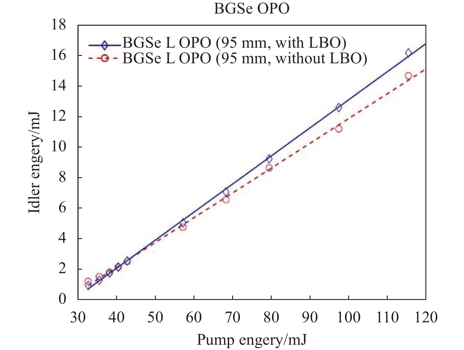
图2给出了L型BGSe OPO腔中,有无LBO倍频晶体时,输出闲频光的能量与输入泵浦光能量之间的关系。

图 2 L型OPO腔中的闲频光输出能量
Figure 2. The idler laser output energy under the L-shaped cavity
如图2所示,红色虚线为L型BGSe OPO腔中无LBO晶体时,输出闲频光与泵浦光能量之间的关系;蓝色实线为L型BGSe OPO腔中有LBO晶体时,输出闲频光与泵浦光能量之间的关系。
从图2可以看出,当泵浦能量较小时 (32.63~42.72 mJ),无LBO晶体的BGSe OPO腔输出能量略大于有LBO晶体的BGSe OPO腔。因为此时腔内信号光强度较小,逆转换程度较小,且无LBO时信号光的损耗较小,因此输出的闲频光能量较大。
当泵浦能量较大时 (57.08~115.33 mJ),无LBO晶体的BGSe OPO腔输出能量小于有LBO晶体的BGSe OPO腔,且随着泵浦能量的增加,差距越来越大。因为此时腔内信号光强度较大,逆转换程度较强,而有LBO时信号光不断转化为倍频红光,逆转换程度得到了抑制,因此输出的闲频光能量较大。
从图2中可以看出,当泵浦能量为115 mJ时,在有LBO晶体的条件下,闲频光能量为16.18 mJ,光光转换效率为14.06%,斜效率为18.40%;在没有LBO晶体的条件下,闲频光能量为14.67 mJ,光光转换效率为12.75%,斜效率为16.25%。
因此文中提出的在L型OPO腔中插入倍频晶体的方法可以抑制普通OPO腔中的逆转换,并大幅提高大能量泵浦条件下的闲频光转换效率。下面从理论上分析其具体原因。
-
为模拟泵浦光、信号光、闲频光以及信号光的倍频光在OPO腔中的场强分布,需要使用三波耦合方程。
在慢变振幅近似条件下,当脉宽大于1 ns且相位完全匹配时,三波耦合方程可简化为公式(1):
$$ \left\{\begin{array}{c}\dfrac{\mathrm{d}{{E}}_{{s}}\left({z}\right)}{\mathrm{d}{z}}=\dfrac{{i}{{\omega }}_{\mathrm{s}}{{d}}_{{e}{f}{f}}}{{{n}}_{\mathrm{s}}{c}}{{E}}_{{p}}{{E}}_{{i}}^{{*}}\\ \dfrac{\mathrm{d}{{E}}_{{i}}\left({z}\right)}{\mathrm{d}{z}}=\dfrac{{i}{{\omega }}_{{i}}{{d}}_{{e}{f}{f}}}{{{n}}_{i}{c}}{{E}}_{{p}}{{E}}_{{s}}^{{*}}\\ \dfrac{\mathrm{d}{{E}}_{{p}}\left({z}\right)}{\mathrm{d}{z}}=\dfrac{{i}{{\omega }}_{p}{{d}}_{{e}{f}{f}}}{{{n}}_{p}{c}}{{E}}_{{s}}{{E}}_{{i}}\end{array}\right. $$ (1) 式中:$ {{E}}_{{j}} ({j}={s},{i},{p}) $为三波在晶体内的场强;deff为晶体的有效非线性系数;$ {{\omega }}_{j} $为三波的圆频率;$ {{n}}_{j} $为三波在晶体中的折射率。
泵浦光一般均为高斯光束,其在时间和空间上均符合高斯分布,即光斑中心处场强E最大,而光斑边缘处场强E较小,高斯脉冲时间峰值处场强E最大,脉冲时间两端场强E最小。因此三波在OPO腔中传输时首先会在光斑中心处、脉冲峰值处出现逆转换,随后扩散到光斑边缘、脉冲边缘处。
文中以高斯光束的时间分布为例,假设泵浦光在光斑半径内的场强处处相等,重点模拟不同脉冲时刻下,三波在OPO腔输出端场强随时间的分布关系,进而得出三波在OPO腔输出端的能量密度。
(1) 泵浦光场强
公式 (1) 中用场强E表示三波的强度,试验中常接触到的参数为泵浦源的单脉冲能量,因此需要将单脉冲能量Q转换为晶体内场强E。根据文献[11],可用公式(2)进行转换:
$$ {{E}}_{0}=\sqrt{\frac{4\sqrt{\mathrm{l}\mathrm{n}2}{Q}}{{{\pi }}^{3/2}{{\varepsilon }}_{0}{c}{n}{\tau }{{\omega }}^{2}}} $$ (2) 式中:$ {{E}}_{0} $为高斯脉冲中心时刻的峰值场强 (假设为均匀光斑); $ {{\varepsilon }}_{0} $为真空中的介电常数;n为泵浦光在晶体中的折射率;τ为半最大值全宽度 (Full Width at Half Maximum,FWHM);$ \mathrm{\omega } $为光斑半径。
(2) 信号光、闲频光的初始场强
对于信号光,初始能量从量子噪声开始,在信号光一次通过晶体的时间内、信号光光斑面积上的能量设为一个光子的能量,其功率密度和场强分别为:
$$ {{I}}_{{s}}=\dfrac{{h}{c}}{{{\lambda }}_{{s}}\cdot{\pi }{{w}}_{{s}}^{2}\cdot \left(\dfrac{{{n}}_{{s}}{l}}{{c}}\right) }\text{,}{{E}}_{{s}}=\sqrt{\dfrac{2{{I}}_{{s}}}{{{{n}}_{{s}}{\varepsilon }}_{0}{c}}} $$ (3) 式中:$ {{\lambda }}_{{s}} $为信号光波长; $ {{w}}_{{s}} $为阈值附近信号光光斑半径。根据文献[12],它与泵浦光光斑半径满足公式(4):
$$ {\left(\frac{{\pi }}{2{L}{{\lambda }}_{s}}\right)}^{2}{{w}}_{{s}}^{6}+{{w}}_{{s}}^{2}-\frac{{{w}}_{{p}}^{2}}{2}=0 $$ (4) 式中:$ {{w}}_{p} $为泵浦光斑半径。需要注意,随着泵浦光能量的增加,信号光光斑半径$ {{w}}_{{s}} $会逐渐增加。
(3) 参量光的模拟波形
根据给定的初值,利用Runge-Kutta算法对公式(1)进行了迭代求解,得到了$ \mathrm{到} $晶体内三波场强与位置的关系。
对于BGSe晶体,通过迭代运算,可以从初始状态的${{{{E}}}}_{{{{p}}}}\left(1\right)$、$ {{E}}_{{s}}\left(1\right) $、$ {{E}}_{{i}}\left(1\right) $依次得到所有位置的$ {{E}}_{{p}}\left({i}\right) $、$ {{E}}_{{s}}\left({i}\right) $、$ {{E}}_{{i}}\left({i}\right) $。由于场强E为复数,将其转换为光强 (功率密度),得到不同时刻三波在OPO腔输出端的光强。其中泵浦光、闲频光、信号光三波波长分别为1.064 μm、3.5 μm和1.53 μm,他们在晶体中的折射率约为2.49。根据BGSe最新的二阶非线性系数矩阵[13]和单斜晶体有效非线性系数的计算方法[14],BGSe (56.3°,0°) 的有效非线性系数为−25.2 pm/V。
对于LBO晶体,从BGSe晶体输出的信号光1.53 μm,将在LBO中倍频产生0.765 μm的倍频光。在R-T算法中,该过程中λp=0.765 μm,λs=λi=1.53 μm。他们在晶体中的折射率约为1.56。LBO (90°,0°) 的有效非线性系数为0.818 pm/V[15]。
为方便对比,给出了泵浦能量分别为30、50、80 mJ情况下L型OPO腔内有LBO和无LBO情况下参量光在OPO腔输出端随时间变化的波形。具体如图3所示。

图 3 (a) 30 mJ 泵浦能量下BGSe-L腔(无LBO)中参量光波形;(b) 30 mJ 泵浦能量下BGSe-L腔(有LBO)中参量光波形;(c) 50 mJ 泵浦能量下BGSe-L腔(无LBO)中参量光波形;(d) 50 mJ 泵浦能量下BGSe-L腔(有LBO)中参量光波形;(e) 80 mJ 泵浦能量下BGSe-L腔(无LBO)中参量光波形;(f) 80 mJ 泵浦能量下BGSe-L腔(有LBO)中参量光波形
Figure 3. (a) Parametric light waveforms in BGSe-L cavity (without LBO) with a pump energy of 30 mJ; (b) Parametric light waveforms in BGSe-L cavity (with LBO) with a pump energy of 30 mJ; (c) Parametric light waveforms in BGSe-L cavity (without LBO) with a pump energy of 50 mJ; (d) Parametric light waveforms in BGSe-L cavity (with LBO) with a pump energy of 50 mJ; (e) Parametric light waveforms in BGSe-L cavity (without LBO) with a pump energy of 80 mJ; (f) Parametric light waveforms in BGSe-L cavity (with LBO) with a pump energy of 80 mJ
图3中,黑色虚线(--)为初始的泵浦光波形,为高斯分布。黑色的实线为OPO腔输出端的泵浦光波形,蓝色点划线(-.)为OPO腔输出端的信号光波形,红色点线(..)为OPO腔输出端的闲频光波形。
如图3(a)、(b)所示,在30 mJ泵浦能量下,此时腔内信号光功率密度较小,当腔内没有LBO晶体时,信号光可以以较小的损耗地在L型腔内振荡增强,因此产生的闲频光能量要大于有LBO时的情况。将图中的闲频光功率密度求和并乘以时间,可以得到闲频光在整个脉冲内的能量密度。图3(a)和图3(b)中的闲频光能量密度分别为16 J/m2和8 J/m2。
如图3(c)、(d)所示,在50 mJ泵浦能量下,此时腔内信号光功率密度较大,闲频光峰值向泵浦光脉冲中心移动,位于中心时刻略偏右侧。图3(c)中心时刻右侧的剩余泵浦光大于图3(d)中的剩余泵浦光,因此逆转换更严重一些。原因在于图3(d)中的LBO晶体消耗了大量的信号光,因此转换效率更高一些。图3(c)和图3(d)中的闲频光能量密度分别为45 J/m2和49 J/m2,此时有LBO情况下的闲频光转换效率已反超无LBO下的情况。
如图3(e)、(f)所示,在80 mJ泵浦能量下,此时腔内信号光功率密度更大,图3(e)中逆转换程度较大,闲频光峰值位于中心时刻略偏左侧,此时右侧的剩余泵浦光高于左侧的泵浦光强度,且闲频光峰值被压制得很低。图3(f)中的逆转换程度较3(e)要小一些,闲频光峰值位于中心时刻略偏左。图3(e)和图3(f)中的闲频光能量密度分别为52 J/m2和62 J/m2,此时有LBO情况下的闲频光转换效率是无LBO情况下的1.2倍。
从模拟图中可以看出,当泵浦能量为80 mJ时,即使在有LBO的条件下,逆转换程度也很强。因此当使用长度更长的LBO或有效非线性系数更高的其他倍频晶体时,抑制逆转换的效果会更好。
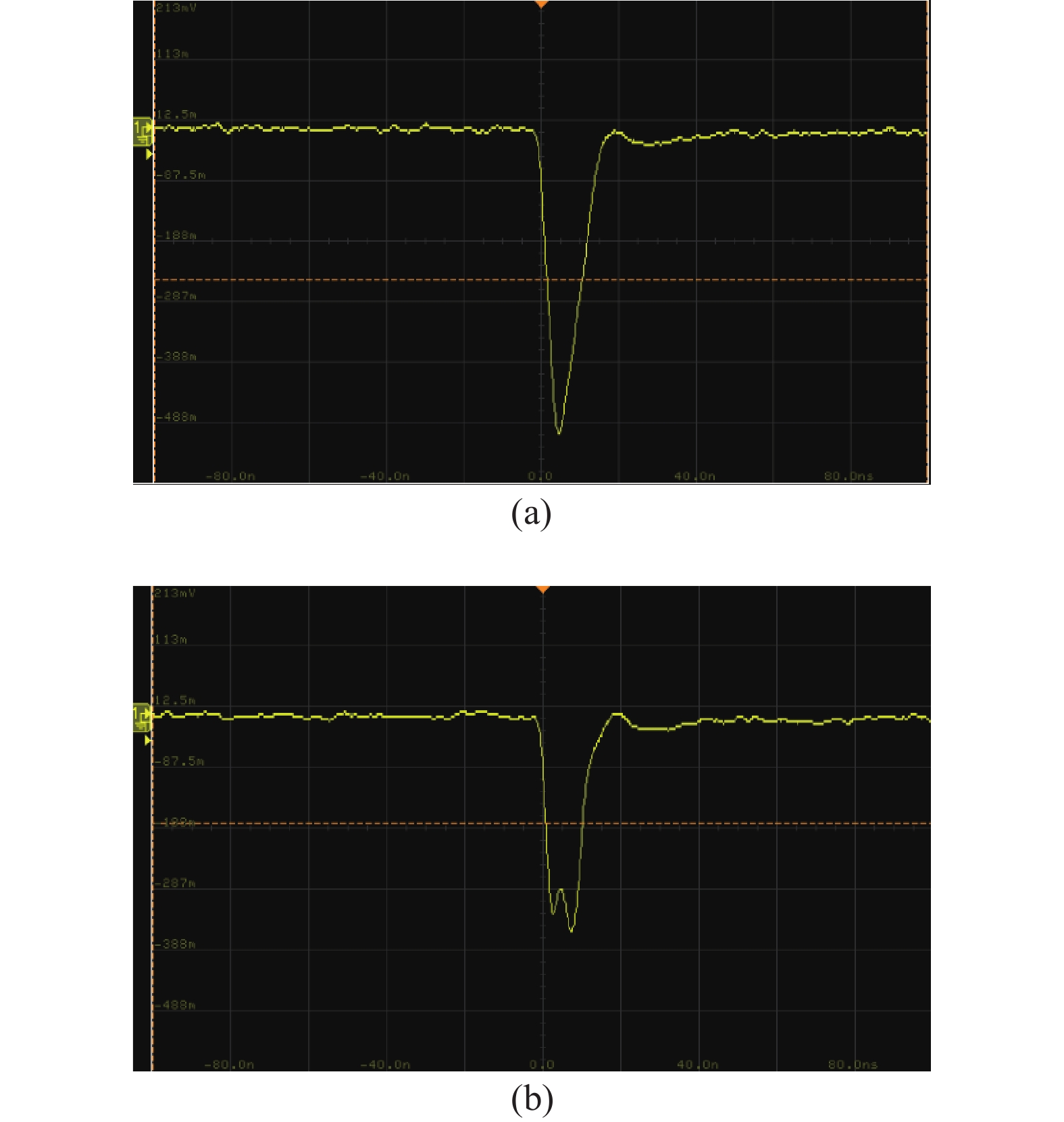
下面给出泵浦能量为78 mJ条件下,BGSe-L腔OPO闲频光的波形,具体如图4所示。

图 4 泵浦能量78 mJ时BGSe-L腔OPO闲频光的波形:(a)有LBO;(b)无LBO
Figure 4. Temporal profile of the idler in BGSe-L cavity at a 78 mJ pump energy: (a) with LBO; (b) without LBO
图4(a)是有LBO条件下的输出闲频光波形,图4(b)是无LBO条件下的输出闲频光波形。图4(a)的闲频光波形类似高斯分布,有一个波峰,其峰值为505 mV;图4(b)的闲频光波形有两个小尖峰,表示OPO腔内出现较为严重的拟转换,其峰值为362 mV,也小于前者。
理论和实验均验证了插入倍频晶体后闲频光的转换效率得到了明显的提升。
-
在50 mJ泵浦能量下,旋转BGSe晶体的角度,测量L型BGSe - LBO OPO腔输出波长,并给出不同输出波长下的输出能量。通过调整晶体的俯仰和水平角度, BGSe L OPO输出的闲频光中心波长与θ、φ之间的关系如图5所示。

图 5 (a) BGSe (56.3$ ° $, 0$ ° $)输出的峰峰值波长与θ之间的关系;(b) BGSe (56.3$ ° $, 0$ ° $)输出的峰峰值波长与φ之间的关系
Figure 5. (a) The relationship between the output wavelength and θ angle of BGSe; (b) The relationship between the output wavelength and φ angle of BGSe (56.3, 0)
图5(a)为通过调整上方调整架的俯仰角度改变晶体的θ角,蓝色实线为根据Badikov等[16]折射率方程计算得出的相位匹配曲线,黑色点划线(-.)为根据Yang等[17]折射率方程计算所得的相位匹配曲线,青色虚线(--)对应Brousier等[18]方程计算所得的曲线,红色点线(..)对应Kato等[19]方程计算所得的曲线,红色“o”为实测的峰值波长。由此可以看出,实测峰值波长的数值与黑色曲线 (Yang)吻合的很好。实测值的$ \Delta {\mathrm{\lambda }}_{2}/\Delta \mathrm{\theta } $为−231.81 nm/(°),四类曲线在3.5 μm附近的$ \Delta {\mathrm{\lambda }}_{2}/\Delta \mathrm{\theta } $分别为−258.71 nm/(°)(Badikov)、−238.22 nm/(°)(Yang)、−247.18 nm/(°)(Brousier)、−210.04 nm/(°)(Kato)。实验与理论比较接近。
如图5(b)所示,通过调整上方调整架的水平角度改变晶体的φ角,实测数据位于Kato和Yang的曲线之间且离Yang的曲线更近一些。当φ从0°增加到0.8°时,四类曲线的变化不大,$ {{\lambda }}_{2} $均仅下降了1 nm,$ \Delta {{\lambda }}_{2}/\Delta {\varphi } $为−1.25 nm/(°)。但实测的$ {\mathrm{\lambda }}_{2} $从3549 nm减小到3 544 nm,下降了5 nm,$ \Delta {{\lambda }}_{2}/\Delta {\varphi } $为−6.25 nm/(°),远大于理论值。可能的原因是,受晶体平台的影响,泵浦光入射方向难以与BGSe的θ=56.3°线完全重合,当使用NVM25.4调整架的旋钮对晶体的φ角进行调整时,θ也有会细微的变化。根据$ \Delta {{\lambda }}_{2}/ \Delta{\theta }=-231.8 $ $\mathrm{n}\mathrm{m}/$(°)推算,当θ改变了0.02°时,闲频光波长$ {\mathrm{\lambda }}_{2} $将会有5 nm的变化。
实验验证了BGSe L LBO腔可以在较大范围内获得波长可调谐的激光输出,原因在于LBO (90°,0°) 的倍频的允许线宽较大,信号光即使不能满足完全相位匹配,也可在较大的波长范围内满足部分相位匹配条件,因此可在较大的闲频光波长范围内输出激光并具有提高闲频光转换效率的效果。另由于BGSe晶体镀了对信号光、闲频光和泵浦光三波高透的增透膜,且晶体的调谐角度较小 (0.8°),实验表明在不同倾角下,闲频光转换效率与正入射时基本保持一致。
-
首次提出在L型OPO腔中插入信号光倍频晶体的方法来抑制大能量泵浦条件下OPO腔内过高的信号光功率密度,从而抑制了信号光和闲频光向泵浦光的逆转换并提高了闲频光转换效率。以BGSe OPO为例,当泵浦能量 (1.06 μm) 为115 mJ时,闲频光 (3.5 μm)能量为16.18 mJ,光光转换效率为14.06%,斜效率为18.4%。这是目前已知1 μm激光泵浦BGSe OPO最高的闲频光转换效率。论文根据OPO数值模拟从理论上分析了该方法提高闲频光转换效率的内在原因。并通过实验验证了该方案同时具有OPO的波长调谐能力。
Mid-infrared BaGa4Se7 optical parametric oscillator with high conversion efficiency (invited)
-
摘要: 为抑制光参量振荡器(Optical Parametric Oscillator,OPO)振荡过程中信号光和闲频光向泵浦光的逆转换,首次采用在L型OPO腔的支路中插入信号光倍频晶体LiB3O5的(简称LBO)的方式,实现了BaGa4Se7(BGSe) OPO闲频光的高转换效率输出,当泵浦激光(1.06 μm)能量为115 mJ时,闲频光(3.5 μm)能量为16.18 mJ,光光转换效率为14.06%,斜效率为18.4%,这是目前已知1.06 μm激光泵浦BGSe OPO最高的转换效率。模拟了不同泵浦能量下L型腔中有无LBO晶体时BGSe OPO腔内的三波波形,并给出了闲频光在实验中的输出波形。与传统OPO腔相比,所提出的L型OPO腔(含倍频晶体)在大能量泵浦条件下抑制了逆转换,可获得更高的闲频光转换效率。Abstract:
The LiB3O5(LBO) was inserted into the branch of the L-shaped BaGa4Se7(BGSe) optical parametric oscillator (OPO) to improve the conversion efficiency for the first time. When the pump laser energy is 115 mJ (1.06 μm), the idler light (3.5 μm) energy was 16.18 mJ, corresponding to the conversion efficiency of 14.06%, and the slope efficiency was 18.4%, which was the highest conversion efficiency of BGSe OPO pumped by 1 μm laser. The signal, idler, and pump wave waveform in BGSe L OPO cavity with and without LBO crystals was simulated, and the output waveform of idler light was given. Compared with traditional OPO cavities, L-type OPO cavities (with frequency doubling crystals) suppress the inverse conversion under high-energy pumping conditions, achieving higher idle frequency light conversion efficiency. Objective The mid-infrared (IR) coherent sources in the 3-5 μm have always been intensively demanded for a wide range of scientific and technological applications in remote sensing, spectrum analysis, materials diagnostics, aerospace fields, etc. Optical parametric oscillation is an attractive approach, especially when high energy and average power are demanded simultaneously. However, there is reverse conversion in the OPO cavity.When the pump energy is high, the signal light and idle frequency light generated are also strong. At this time, the signal light and idle frequency light will be converted to the pump light, which seriously affects the conversion efficiency of OPO. In addition, due to the high intensity of signal light in the cavity during the reverse conversion, it is easy to damage the nonlinear crystal or its coating.Therefore, how to suppress reverse conversion in the OPO cavity under high-energy pumping conditions and improve the conversion efficiency of OPO has always been the focus of research. Methods To suppress the inverse conversion in the OPO cavity, we proposed a method of inserting a frequency doubling crystal into the L-type OPO cavity to suppress the signal light intensity (Fig.1). All three mirrors of the L-shaped cavity are coated with a high-reflection coating for the signal laser, and crystals are inserted in the L-branch to achieve intracavity frequency doubling of the signal laser. When the energy density of the signal laser in the OPO cavity is high, the signal laser is converted into red light by the frequency doubling crystal and output from the L branch. At the same time, the signal laser is attenuated, reverse conversion is suppressed, and the efficiency of idle laser conversion is improved. Results and Discussions The idler laser energy was 16.18 mJ at a pump energy of 115 mJ, corresponding to an optical-to-optical conversion efficiency of 14.06% and a slope efficiency of 18.4% (Fig.2). It is the highest conversion efficiency for BaGa4Se7 (BGSe) OPO pumped by a 1.06 μm laser, to the best of our knowledge. The energy density of the three waves at the output of the OPO cavity is simulated. The simulation results show that the optical-to-optical conversion efficiency of the idler laser with the LiB3O5 (LBO) inserted in the cavity is 1.20 times higher than that without LBO in the cavity at a pump energy of 80 mJ (Fig.3). The OPO output wavelength could be tuned by adjusting the angle of the BGSe crystal (Fig.5). When the θ angle of the crystal is changed, the experimental peak wavelength agrees well with the theoretical simulation curve, and the measured $ \Delta {{\lambda }}_{2}/\Delta \mathrm{\theta } $ is −231.81 nm/(°) . When changing the φ angle of the crystal, the measured $ \Delta {{\lambda }}_{2}/\Delta {\varphi} $ of −6.25 nm/(°) deviates from the theoretical value of −1.25 nm/(°) because the incident direction of the pump laser is difficult to exactly coincide with the θ=56.3° line of BGSe. Conclusions The conversion efficiency of idler light in OPO cavity was improved by inserting a signal laser frequency doubling crystal into the L-shaped OPO cavity for the first time. When the pump energy is 115 mJ, the 16.18 mJ of the idler laser energy was obtained in BGSe OPO. The optical-to-optical conversion efficiency was 14.06%, and the slope efficiency was 18.4%, which is the highest conversion efficiency of BGSe OPO pumped by a 1.06 μm laser. The output wavelength of BGSe OPO with high conversion efficiency can also be tuned. -
图 3 (a) 30 mJ 泵浦能量下BGSe-L腔(无LBO)中参量光波形;(b) 30 mJ 泵浦能量下BGSe-L腔(有LBO)中参量光波形;(c) 50 mJ 泵浦能量下BGSe-L腔(无LBO)中参量光波形;(d) 50 mJ 泵浦能量下BGSe-L腔(有LBO)中参量光波形;(e) 80 mJ 泵浦能量下BGSe-L腔(无LBO)中参量光波形;(f) 80 mJ 泵浦能量下BGSe-L腔(有LBO)中参量光波形
Figure 3. (a) Parametric light waveforms in BGSe-L cavity (without LBO) with a pump energy of 30 mJ; (b) Parametric light waveforms in BGSe-L cavity (with LBO) with a pump energy of 30 mJ; (c) Parametric light waveforms in BGSe-L cavity (without LBO) with a pump energy of 50 mJ; (d) Parametric light waveforms in BGSe-L cavity (with LBO) with a pump energy of 50 mJ; (e) Parametric light waveforms in BGSe-L cavity (without LBO) with a pump energy of 80 mJ; (f) Parametric light waveforms in BGSe-L cavity (with LBO) with a pump energy of 80 mJ
图 4 泵浦能量78 mJ时BGSe-L腔OPO闲频光的波形:(a)有LBO;(b)无LBO
Figure 4. Temporal profile of the idler in BGSe-L cavity at a 78 mJ pump energy: (a) with LBO; (b) without LBO
-
[1] Gao Baoguang, Meng Dondong, Qiao Zhanduo, et al. High repetition rate, high peak power mid-infrared optical parametric oscillator based on MgO: PPLN [J]. Infrared and Laser Engineering, 2022, 51(10): 20220069. (in Chinese) [2] Wang Huahang, Mao Jiajia, Ye Shuai, et al. Research progress of high-power 266 nm all-solid-state single-frequency CW laser [J]. Infrared and Laser Engineering, 2023, 52(4): 20220885. (in Chinese) [3] Liu Jianhui, Liu Qiang, Gong Mali. Back conversion in optical parametric process [J]. Acta Phys Sin, 2011, 60(2): 024215. (in Chinese) [4] Wang L, Xing T, Hu S, et al. Mid-infrared ZGP-OPO with a high optical-to-optical conversion efficiency of 75.7% [J]. Opt Express, 2017, 25(4): 3373-3380. doi: 10.1364/OE.25.003373 [5] Wang P, Li X, Wang K, et al. Highly-efficient pulsed mid-infrared generation based on intracavity difference frequency mixing [J]. IEEE Photonics Journal, 2021, 13(3): 1500309. [6] Kong Hui, Bian Jintian, Ye Qing, et al. Comparison of mid-infrared laser generatedby optical parametric oscillation of BaGa4Se7 and KTiAsO4 [J]. Infrared and Laser Engineering, 2020, 49(5): 20190423. (in Chinese) [7] Yao J, Mei D, Bai L, et al. BaGa4Se7: A new congruent-melting IR nonlinear optical material [J]. Inorganic Chemistry, 2010, 49(20): 9212-9216. doi: 10.1021/ic1006742 [8] Zhang X, Yao J, Yin W, et al. Determination of the nonlinear optical coefficients of the BaGa4Se7 crystal [J]. Optics Express, 2015, 23(1): 552-558. doi: 10.1364/OE.23.000552 [9] Kong Hui, Bian Jintian, Yao Jiyong, et al. Temperature tuning of BaGa4Se7 optical parametric oscillator [J]. Chinese Optics Letters, 2021, 19(2): 021901. doi: 10.3788/COL202119.021901 [10] Kang M, Deng Y, Yan X, et al. A compact and efficient 4.25 μm BaGa4Se7 optical parametric oscillator [J]. Chinese Optics Letters, 2019, 17(12): 53-56. [11] 孔辉. 基于BaGa4Se7和KTiOAsO4的中红外光参量振荡器研究[D]. 国防科技大学, 2021. Kong Hui. Mid infrared optical parametric oscillator based on BaGa4Se7 and KTiOAsO4 [D]. Changsha: National University of Defense Technology, 2021(in Chinese). [12] Brosnan S, Byer R. Optical parametric oscillator threshold and linewidth studies [J]. IEEE Journal of Quantum Electronics, 1979, 15(6): 415-431. doi: 10.1109/JQE.1979.1070027 [13] Zhao X, Li C, Bai J, et al. Recalibration of the nonlinear optical coefficients of BaGa4Se7 crystal using second-harmonic-generation method [J]. Optics Letters, 2021, 46(23): 5894-5897. doi: 10.1364/OL.446333 [14] Kong Hui, Bian Jintian, Sun Xiaoquan. Calculation of phase-matching angles and effective nonlinear coefficients of BaGa4Se7 crystals [J]. Optik, 2019, 193: 163004. doi: 10.1016/j.ijleo.2019.163004 [15] 孙芮. LD抽运Nd: YAG腔内LBO倍频659.5 nm/669 nm双波长激光器研究[D]. 2016. Sun Rui. Investigation on LD-pumped Nd: YAG intracJavity LBO frequency doubling 659.5 nm/669 nm dual-wavelength laser[D]. Changchun: Changchun University of Science and Technology, 2016. (in Chinese) [16] Badikov V, Badikov D, Shevyrdyaeva G, et al. Phase-matching properties of BaGa4S7 and BaGa4Se7: Wide-bandgap nonlinear crystals for the mid-infrared [J]. Phys. Status Solidi RRL, 2011, 5(1): 31-33. doi: 10.1002/pssr.201004425 [17] Yang F, Yao J, Xu H, et al. Midinfrared optical parametric amplifier with 6.4–11 μm range based on BaGa4Se7 [J]. IEEE Photonics Technology Letters, 2015, 27(10): 1100-1103. doi: 10.1109/LPT.2015.2407895 [18] Boursier E, Segonds P, Debray J, et al. Angle noncritical phase-matched second-harmonic generation in the monoclinic crystal BaGa4Se7 [J]. Optics Letters, 2015, 40(20): 4591-4594. doi: 10.1364/OL.40.004591 [19] Kato K, Miyata K, Petrov V, et al. Phase-matching properties of BaGa4Se7 for SHG and SFG in the 0.901–10.5910 μm range [J]. Applied Optics, 2017, 56(11): 2978-2981. doi: 10.1364/AO.56.002978 -

 点击查看大图

计量
- 文章访问数: 200
- HTML全文浏览量: 67
- PDF下载量: 35
- 被引次数: 0

