


-
目前在中红外波段,目标的光谱特性获取手段主要以红外滤波轮[1]为主,但波段数的限制依然是其瓶颈问题,且滤波片波段固定,对于不同目标,不具备可选光谱数据的获取,适应性差。声光可调谐滤波器作为一种新型的光谱分光器件,通过超声换能器产生的高频正弦信号调制声光晶体内的声波的频率、主瓣方向、声波强度,可实现改变对应衍射光的波长、出射方向以及出射强度的目的[2-3]。相比于其他光谱分光方式,更为灵活。此外,它还具有电控、全固态、调谐速度快、大角孔径、宽光谱范围等优点[4-5]。AOTF光谱仪在光谱分析、激光整形、光谱显微镜等领域中得到了广泛的应用。
中红外AOTF用于目标光谱探测时,有两种光学结构,即会聚光入射与平行光入射结构[6]。对于会聚光入射结构的AOTF系统,存在光谱带宽展宽的问题;对于平行光入射结构的AOTF系统,存在光谱漂移的问题[7-9]。而对于中波红外波段,其光谱漂移现象相比于可见光波段更为严重。针对光谱漂移的问题,国外Pozhar等人已通过计算成像的方式将AOTF的视场进行拓展与光谱离线校正[10],并成功运用于基于立体光谱成像应用之中[11],但其方法为数据后处理,无法满足实时性的要求。其次,其建立的为物方视场中心波长映射关系,未考虑由畸变引起的物像不相似问题[12]。因此,文中从AOTF的声光衍射机理进行建模分析,设计并搭建了中波红外AOTF光谱成像探测系统,在调谐曲线计算公式的基础之上,考虑加入衍射光出射角度这一已知要素,通过三维逆向光线追迹的方法,建立像素级调谐曲线计算方法,实现了全视场目标光谱的实时在线校准。
-
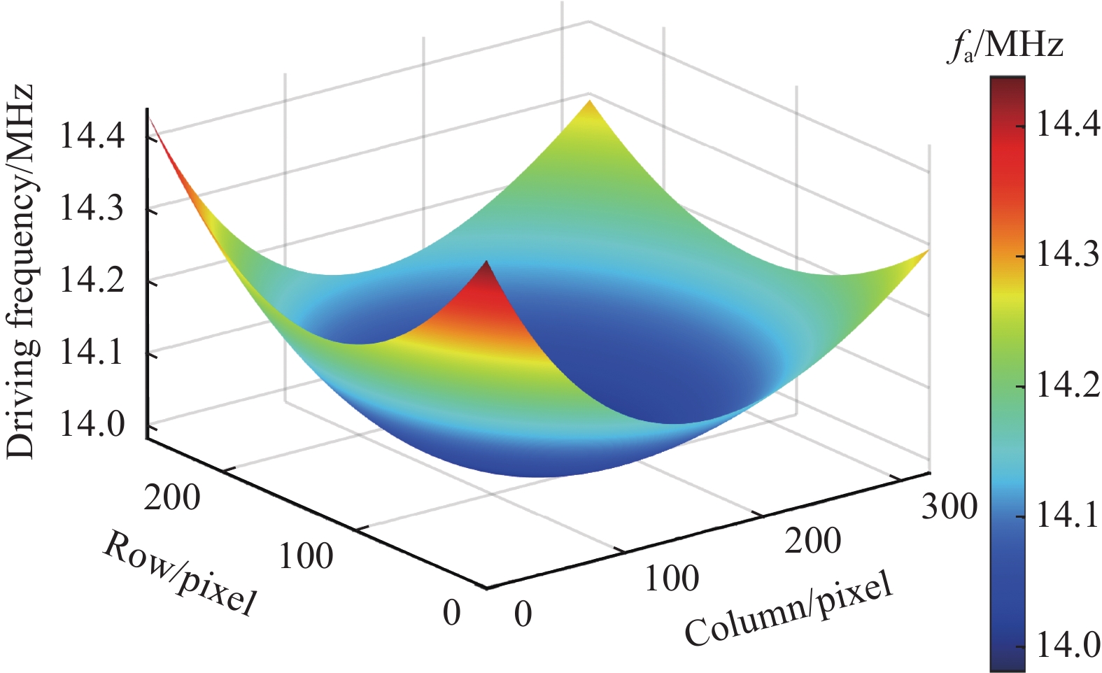
AOTF器件一般为反常布拉格衍射,入射光与衍射光具有不同的偏振态,声光互作用长度较长,产生±1级衍射光,即有两种工作模式:1)入射光为非常光(简称e光),衍射光为常光(简称o光);2)入射光为o光,衍射光为e光。在中红外波段,由于折射率随波长变化的色散差异程度小,因而横向色差较小,那么为了使轴向色差小,常采用平行光入射的结构。由任意角度入射AOTF的频率与波长的调谐计算公式[13],通过数值计算的方法,可以得到像面的频率漂移,如图1所示。

图 1 像面频率漂移
Figure 1. Frequency drift on image plane
像面的频率漂移呈现凹函数分布,并在像面正中心出现极小值点,对应正中心视场。在图像行方向,频率漂移为对称分布;在图像列方向,频率漂移为非对称分布,一侧漂移更为严重。AOTF的调谐曲线为一单调函数,那么频率漂移将最终导致光谱漂移,且越靠近边缘视场,漂移现象越严重,但实际情况入射光为复色光。根据动量匹配原则[7],当AOTF驱动频率确定时,存在唯一确定的衍射光波长与之对应。衍射光波长与入射光角度、驱动频率相关,那么根据光路可逆,可由像面目标位置与驱动频率的已知信息,可反向解算衍射光波长。
-
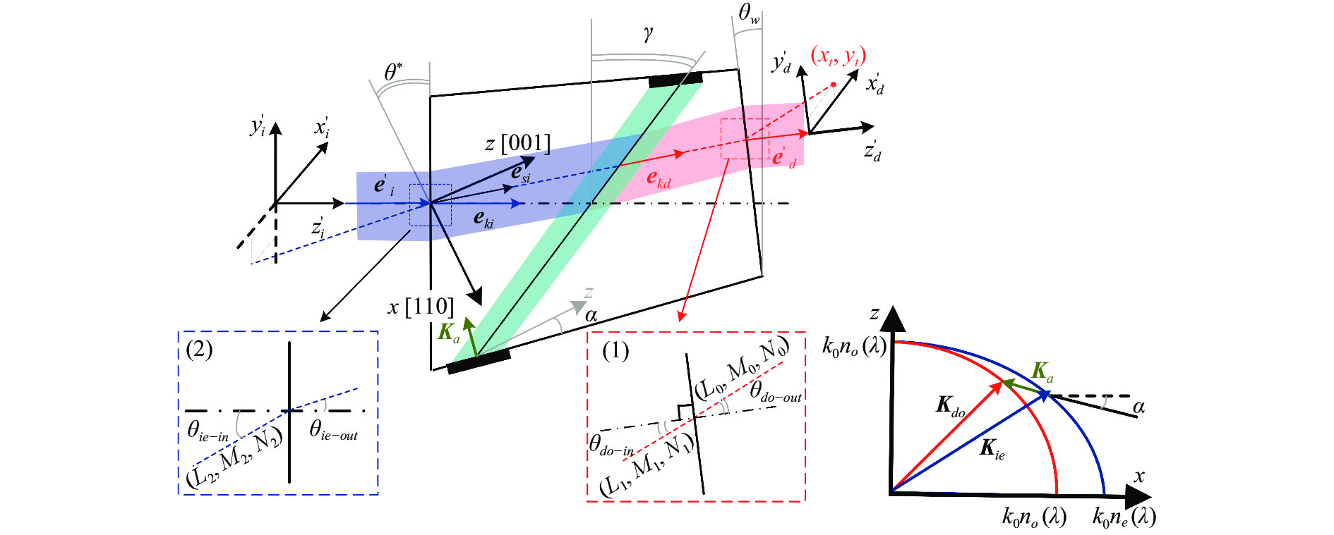
根据实际光谱成像探测系统的光学结构,可构建出基于动量匹配的逆向光线追迹模型,示意图如图2所示。

图 2 逆向光线追迹示意图
Figure 2. Schematic diagram of reverse ray tracing
像面衍射光的位置通过图像滤波、阈值分割、质心提取等基本的图像处理方法获得。图2中$ \boldsymbol{K}_{a} $为声矢量,$\boldsymbol{K}_{ie}$、$\boldsymbol{K}_{do}$分别代表入射光为e光,衍射光为o光, $ k_{0} $表示波数,且$ k_{0}=2 \pi / \lambda $。$n_{o}(\lambda)$、$ n_{e}(\lambda) $表示晶体的主折射率,与入射光波长有关。$\boldsymbol{e}_{ki}$与${\boldsymbol{e}}_{{kd}}$分别代表入射光和衍射光方向的单位向量,${{\boldsymbol{e}}}_{ {si }}$为入射光能速度方向单位向量,$ \gamma $为声走离角。$ \left(L_{0}, M_{0}, N_{0}\right) $为衍射光出射方向余弦,$ \left(x_{t}, y_{t}\right) $表示目标像面成像坐标,$\theta_{{{do}}\text{-}{{o u t}}}$为衍射光与AOTF晶体后表面法线夹角,$ \theta_{w} $为AOTF晶体后楔角,$ \left(L_{1}, M_{1}, N_{1}\right) $为晶体内衍射光方向余弦,${\theta}_{{{do}}\text{-}{{i n}}}$为晶体内衍射光与AOTF晶体后表面法线夹角。$ \theta^{*} $为入射面切角,$\theta_{ie {\text{-}out }}$为晶体内折射光与入射面法线的夹角,$\theta_{{ie}{\text{-}}{in}}$为入射光与入射面法线的夹角,$ \left(L_{2}, M_{2}, N_{2}\right) $为入射光方向余弦。整个光线追迹流程为通过$ \left(L_{0}, M_{0}, N_{0}\right) $与实时驱动频率,解算入射光波长与方向$ \left(L_{2}, M_{2}, N_{2}\right) $。
-
由于引入了AOTF声光晶体,因而坐标系中加入了晶体坐标系。图2中,$ {{\boldsymbol{x}}}_{d}^{\prime} $对应像面行方向,$ y_{d}^{\prime} $对应像面列方向。晶体坐标系与世界坐标系涉及到坐标系之间的二维旋转转换,可定义旋转矩阵$ T $,如公式(1)所示:
$$ T(\theta)=\left(\begin{array}{cc} \cos \theta & -\sin \theta \\ \sin \theta & \cos \theta \end{array}\right) $$ (1) 式中:$ \theta $为坐标系的旋转角度,顺时针旋转时角度取正值,逆时针旋转时角度取负值。在系统装调时,会采用激光器输出某一参考波长进行光轴的准直校准,使正入射激光器的衍射光成像位置位于像面正中心。可得到世界坐标系下衍射光的方向余弦$ \left(L_{0}, M_{0}, N_{0}\right) $,如公式(2)所示:
$$ \begin{gathered} L_0=-\frac{L_a}{\sqrt{L_a^2+L_b^2+L_c^2}} \\ {\left[\begin{array}{l} M_0 \\ N_0 \end{array}\right]=T\left(-\theta_{{axis }}\right)\left[\begin{array}{l} L_b / \sqrt{L_a^2+L_b^2+L_c^2} \\ L_c / \sqrt{L_a^2+L_b^2+L_c^2} \end{array}\right]} \end{gathered} $$ (2) 式中:$ \theta_{a x i s} $为入射光垂直晶体前表面入射时,衍射光的偏转角;$ \left(L_{a}, L_{b}, L_{c}\right) $为衍射光偏移像面中心的距离。使用折射定律时,入射光、入射平面法线、折射光需位于同一平面,坐标系的建立需要在晶体表面对应的球坐标系下进行。因此,需要先将世界直角坐标系转换至晶体后表面直角坐标系,晶体外衍射光的方向余弦为:
$$ \left\{\begin{array}{c} L_{0}^{\prime}={L}_{0} \\ {\left[\begin{array}{c} M_{0}^{\prime} \\ N_{0}^{\prime} \end{array}\right]=T\left(-\theta_{w}\right)\left[\begin{array}{c} M_{0} \\ N_{0} \end{array}\right]} \end{array}\right. $$ (3) 由于衍射光为o光,晶体内折射率为$n_{{\rm{o}}}$,可求得球坐标系下晶体外衍射光与入射面法线夹角,如公式(4)所示:
$$ \left\{\begin{array}{c} \theta_{{{{{d o}}{\text{-}}{{o u t}}}}}=\arcsin \left(\sqrt{L_0{ }^{\prime 2}+M_0{ }^{\prime 2}}\right)\left(\theta_{{{d o}}\text{-}{{o u t}}} \in\left[0, \dfrac{\pi}{2}\right)\right) \\ \left\{\begin{array}{c} \varphi_{{{d o}}{\text{-}} { {{out}} }}=\arctan \left(M_0{ }^{\prime} / L_0{ }^{\prime}\right)\left(L_0{ }^{\prime}>0 \& M_0{ }^{\prime}>0\right) \\ \varphi_{{{do}}\text{-} { {{out}} }}=\pi+\arctan \left(M_0{ }^{\prime} L_0{ }^{\prime}\right)\left(L_0{ }^{\prime}<0 \& M_0{ }^{\prime}>0\right) \\ \varphi_{{{d o}}\text{-}{{o u t}}}=\pi+\arctan \left(M_0{ }^{\prime} / L_0{ }^{\prime}\right)\left(L_0{ }^{\prime}>0 \& M_0{ }^{\prime}<0\right) \\ \varphi_{ {{{do}}\text{-}{{out}} }}=2 \pi+\arctan \left(M_0{ }^{\prime} / L_0{ }^{\prime}\right)\left(L_0{ }^{\prime}<0 \& M_0{ }^{\prime}<0\right) \end{array}\right. \end{array}\right. $$ (4) 式中:$ \theta_{{{do}}\text{-}{{o u t}}} $为球坐标系下晶体外衍射光入射极角;$ \varphi_{{{do}}\text{-} {{{ out}} }} $为入射方位角。由入射光、入射面法线、折射光共面原则,即$\varphi_{{{do}}\text{-}{{i n}}}=\varphi_{{{do}} {\text{-}} {out }}$,则晶体后表面直角坐标系下晶体内衍射光的方向余弦$ \left(L_{1}, M_{1}, N_{1}\right) $为:
$$ \left\{\begin{array}{c} L_{1}=\sin \theta_{{{do}}\text{-}{{in}}} \cos \varphi_{{{do}}\text{-}{{i n}}} \\ M_{1}=T\left(\theta_{w}+\theta^{*}\right) \sin \theta_{{{do}}\text{-}{{i n}}} \sin \varphi_{{{do}}\text{-}{{in}}} \\ N_{1}=T\left(\theta_{w}+\theta^{*}\right) \cos \theta_{{{do}}\text{-}{{in}}} \end{array}\right. $$ (5) -
当超声频率确定时,总能找到某个衍射光波长,在某方向上满足动量匹配条件。在该条件下衍射光矢量末端位于o光折射率圆球之上,为方便计算,将三维波矢量布局做同尺度缩放处理(同除$ 2 \pi / \lambda $),缩放后波矢量布局如图3所示。

图 3 缩放后的波矢量布局
Figure 3. Layout of the scaled wave vector
OAB构成封闭三角形。如图3所示,OA为衍射光波矢,OB为晶体内折射光波矢。由晶体坐标系下衍射光的方向余弦可得到A点坐标$ \left(x_{A}, y_{A}, z_{A}\right) $。AB为声波矢,位于声光互作用平面内,其方向是由超声切角α确定,声矢量斜率$ k=\tan \alpha $,可得到AB的直线方程,又因为入射e光波矢位于椭球折射率曲面之上,即B点坐标满足椭球方程,联立方程组(6)可解得B点坐标$ \left(x_{B}, y_{B}, z_{B}\right) $。
$$ \left\{\begin{array}{c} x_{B}=x_{A} \\ z_{B}-z_{A}=k\left(y_{B}-y_{A}\right) \\ \dfrac{x_{B}^{2}}{n_{{\rm{e}}}^{2}}+\dfrac{y_{B}^{2}}{n_{{\rm{e}}}^{2}}+\dfrac{z_{B}^{2}}{n_{{\rm{o}}}^{2}}=1 \end{array}\right. $$ (6) 此时对应的e光折射率为$n_{{\rm{e}}}^{\prime}=\sqrt{x_{B}^{2}+y_{B}^{2}+z_{B}^{2}}$,入射光对应晶体内折射光的方向余弦$ \left(L_{2}^{\prime}, M_{2}^{\prime}, N_{2}^{\prime}\right) $为:
$$ \left[\begin{array}{c} L_{2}^{\prime} \\ M_{2}^{\prime} \\ N_{2}^{\prime} \end{array}\right]=\left[\begin{array}{c} x_{B} / n_{e}^{\prime} \\ y_{B} / n_{e}^{\prime} \\ z_{B} / n_{e}^{\prime} \end{array}\right] $$ (7) 最后由折射定律可得到入射光在世界直角坐标系下的方向余弦为$ \left(L_{2}, M_{2}, N_{2}\right) $。声矢量$ \boldsymbol{K}_{\boldsymbol{a}} $的长度为线段AB的模乘以$ 2 \pi / \lambda $,由$ \left|{\boldsymbol{K}}_{a}\right|=2 \pi f /\left|{\boldsymbol{V}}_{a}\right| $可得到此时动量匹配下的超声频率$ f $,通过优化迭代算法使得$f=f_{{\rm{a}}}$时,最终可得到衍射光的中心波长,实现由目标像面光谱成像的位置与超声频率直接解算目标对应光谱中心波长,从而实现动态光谱实时校准。以入射光中心波长为4000 nm,中波探测器像面为320×256,系统焦距为50 mm为仿真输入参数,可得到像面频率漂移曲面,如图1所示。若采用同一个调谐曲线计算公式[14],则目标光谱会产生漂移,如图4中曲面所示。采用文中光谱校准方法后,理想仿真校正结果如图4中平面所示。

图 4 光谱校正仿真
Figure 4. Simulation of spectral correction
-
在理论分析的基础之上,搭建了基于平行光入射结构的中红外AOTF光谱成像探测系统,性能参数如表1所示。动态光谱漂移校正的验证实验采用美国光电工业公司(Electro Optical Industries, Ins.(EOI))生产的高温黑体与瑞典Spectrogon带通红外滤光片组合作为窄带目标光源,滤波片中心波长标称值为4475 nm (记为$ \lambda_{s} $),光谱半高宽(full width at half maxima, FWHM)为260 nm (记为$FW H M_{\text {filter }}$)。使组合光源置于不同视场处进行光谱校准实验。
表 1 中波红外AOTF光谱成像探测系统的性能参数
Table 1. Performance parameters of mid-infrared AOTF spectral imaging detection system
Performance index Parameter value Working band 3.7-4.8 μm Focal length 50 mm Number of pixels 320×256 Pixel size 30 μm×30 μm Spectral resolution 44 nm (average) Cut angle 8.9° Rear wedge angle of AOTF 0° -
为了模拟运动目标位于探测系统不同视场的情形,将原理样机置于升降台上,模拟目标行方向上的运动;将组合光源置于小推车上,模拟目标列方向上的运动。光谱校正实验目标光源与测试样机如图5所示。
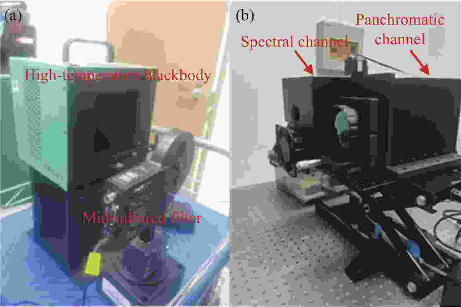
图 5 光谱校正实验目标光源与测试样机。(a)目标光源;(b)测试样机
Figure 5. Light source and prototype of the spectral correction experiment. (a) Light source; (b) Prototype
目标光谱因视场不同在像面列方向漂移更为严重,验证实验综合考虑后设置如图6所示采样点。通过调整黑体水平位置与样机高度,AOTF驱动器扫频,完成同一目标不同视场的频率响应数据获取。黑体温度设置为100 ℃,相机积分时间为2 ms。

图 6 光谱漂移校正实验采样点设置
Figure 6. Setting of sampling points for spectral drift correction experiment
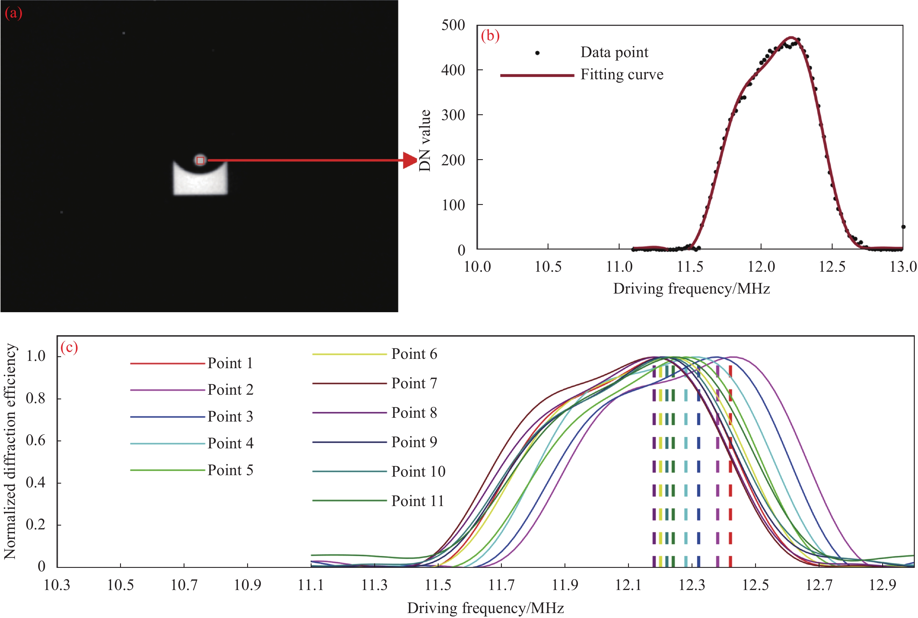
1号采样点为左上,由列方向以此递增,共计33个采样点。为了消除因视场不同AOTF衍射效率的差异,频率响应的拟合采用归一化衍射效率来替代。频率响应拟合采用四次傅里叶级数,以17号标定点为例,实际采样点的ROI区域选取与频率响应拟合如图7(a)、(b)所示。以相同的方法分别获取1~33号采样点的频率响应曲线并做衍射效率归一化处理,这里展示1~11号采样点的频率响应结果如图7(c)所示。

图 7 频率响应测试结果。(a) ROI区域选取;(b)频率响应拟合;(c) 1~11号采样点频率响应
Figure 7. Test results of frequency response. (a) Selection of ROI region; (b) Fitting of frequency response; (c) Frequency response of sampling points 1-11
由图7(c)可以发现,当目标位于AOTF成像光谱仪不同视场时,像面会产生频率漂移。因此用同一个固定的调谐曲线计算公式,由超声频率计算光谱响应时,则导致光谱漂移。
-
以目标频率响应的峰值点作为特征点,对应的中心波长作为特征波长,由调谐曲线计算公式可计算得到目标不同视场光谱未校准时的光谱响应,结果如图8(a)所示。采用文中提出的基于声光互作用的光谱校准方法,得到校准后的各视场光谱响应,结果如图8(b)所示。以峰值波长作为特征点的全视场校正结果如图9所示。

图 8 光谱校准结果。(a)光谱校准前;(b)光谱校准后
Figure 8. Spectral calibration results. (a) Before spectral calibration; (b) After spectral calibration
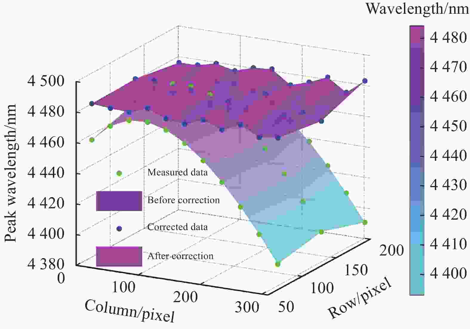
图 9 全视场校正结果
Figure 9. Correction results of full field
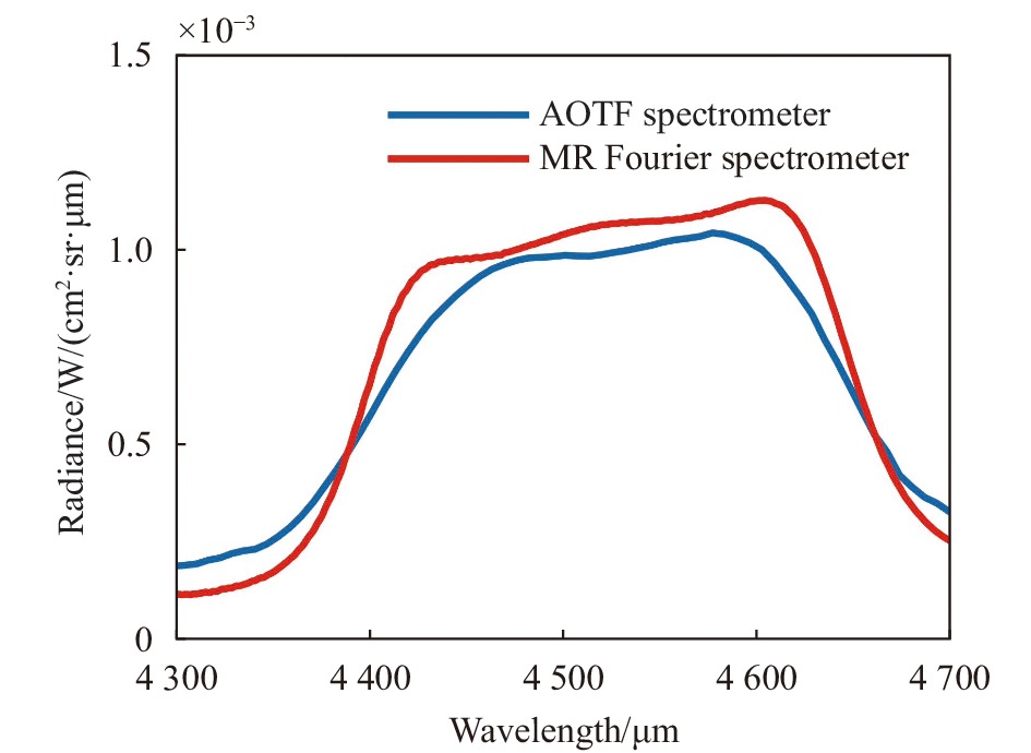
由图8可以看出,光谱校正前,各视场目标光谱响应形状相似,但在光谱维产生漂移,光谱校正后,各曲线基本重合,保留了目标原始的光谱特征。由图9可以看出,光谱校正前,不同视场的目标光谱存在不同程度的漂移现象,且边缘视场漂移更为严重,这与模型仿真的结果相吻合;光谱校正后,不同视场目标的峰值波长基本位于同一平面,漂移现象得到了明显的抑制。同时,利用MR304傅里叶光谱仪对模拟场景进行了实际测量,与AOTF光谱仪辐射定标后的光谱响应(平滑处理以抑制随机噪声)进行对比,结果如图10所示。傅里叶光谱仪测试过程中的分辨率选为1 cm−1,校正后的光谱响应与MR测试结果接近。

图 10 光谱响应对比
Figure 10. Comparison of spectral response
方便展示,以1~11号采样点为例,光谱校正前后的目标峰值波长,峰值波长相比于滤波片标称值的漂移量数据如表2所示。为了更为直观的反映漂移的校正效果,以公式(8)作为光谱漂移量的评价依据。表中也列出了校正前后光谱漂移量最大的采样点。
表 2 1~11号采样点光谱漂移校正结果
Table 2. Spectral drift correction results for sampling points 1-11
Peak wavelength/nm Spectral drift/nm Relative error Original Corrected Original Corrected Original Corrected 1 4459.32 4482.92 −15.68 7.92 6.03% 3.04% 2 4470.30 4481.71 −4.70 6.71 1.81% 2.58% 3 4475.75 4481.02 0.75 6.02 0.29% 2.32% 4 4476.51 4485.34 1.51 10.34 0.58% 3.98% 5 4473.24 4480.52 −1.76 5.52 0.68% 2.12% 6 4466.54 4478.95 −8.46 3.95 3.25% 1.52% 7 4456.91 4483.52 −18.09 8.52 6.96% 3.28% 8 4444.78 4479.02 −30.22 4.02 11.62% 1.55% 9 4430.53 4484.20 −44.47 9.20 17.10% 3.54% 10 4414.49 4477.88 −60.51 2.88 23.27% 1.11% 11 4396.95 4479.23 −78.05 4.23 30.02% 1.63% 19 4451.11 4486.54 −23.88 11.54 9.19% 4.45% 29 4452.09 4475.21 −22.91 0.21 8.81% 0.08% 33 4393.06 4485.42 −81.94 10.42 31.51% 4.01% $$ \begin{split} \\ \text { 相对误差 }=\frac{\left|\lambda_t-\lambda_s\right|}{F W H M_{\text {filter }}} \times 100 \text{%} \end{split} $$ (8) 式中:$ \lambda_{t} $为测试得到的峰值波长;$ \lambda_{s} $为滤波片标称中心波长;$ F W H M_{\text {filter }} $为滤波片标称带宽。
选取的33个采样点中,光谱校准前均有不同程度的光谱漂移,最大的光谱漂移量达到81.94 nm,对应的为33号采样点,由像面位置可知为边缘视场采样点,相对误差为31.51%@4475 nm,光谱已严重偏离目标真实光谱。与实际的仿真结果相吻合。
由文中提出的三维逆向光线追迹方法对光谱进行校准后,最大光谱漂移量为11.54 nm,对应19号采样点,相对误差为4.45%@4475 nm,最小漂移量为0.21 nm,对应29号采样点,相对误差为0.08%@4475 nm。之所以仍然存在校准误差有以下几个因素:1)对于平行光入射结构,不同视场入射光的衍射带宽有所差异;2)系统装调误差拟合存在误差;3)对目标频率响应采样过程中存在随机采样误差与拟合误差。对于算法速度的评价,单个视场目标光谱校正的时间为2.62 ms。若以画幅式成像25 Hz帧频为指标依据,耗费时间小于1/10周期。
如若采用以目标的温度及发射率为特征作为探测识别的依据,可以假设被测目标为灰体,温度为500 K,发射率为0.8,在不考虑辐射量测量误差的前提下,由光谱漂移量利用普朗克公式可以得到光谱校准前的测温最大误差为3.47% (17.36 K);校准后的测温最大误差为0.91% (4.56 K),最小测温误差为0.018% (0.09 K)。
-
基于声光互作用机理的光谱校准方法,对不同视场的目标进行了光谱校准。实验结果表明,同一目标不同视场成像均存在光谱漂移现象,最大相对误差达到31.51%。采用文中方法校准之后,光谱漂移现象可明显抑制,相对误差均控制在4.45%@4475 nm以内。校准的输入信息为目标像面的实时坐标与实时驱动频率,输出为实时解算的衍射光中心波长,因此方法适用于运动目标光谱的在线校正,可将AOTF由静态目标向动态目标的光谱成像探测做推广应用;除此之外,该方法也可进一步解算空间维信息,对AOTF声光作用引起的成像畸变予以校正。
Spectral calibration method for mid-infrared AOTF imagers
-
摘要: 针对基于中红外声光可调谐滤波器(Acousto-Optic Tunable Filter, AOTF)的光谱成像系统观测运动目标过程存在光谱数据漂移问题,提出了一种基于声光互作用的在线光谱校准方法。根据目标光谱成像位置与驱动频率,构建了逆向光线追迹模型,从而实现了光谱数据的在线校准,满足运动目标探测的实时性要求。该方法能为后续目标检测、识别与跟踪提供稳定且精确的光谱数据立方体。在实验验证方面,利用设计研制的平行光入射的中红外AOTF光谱探测系统,以黑体与中红外滤波片组合作为目标光源,对光谱校准模型开展实验验证。最终实验结果表明,针对位于不同视场处的模拟运动目标,校正后的光谱漂移相对误差均优于4.45%,有利于提升对运动目标光谱探测的应用能力。Abstract:
Objective Spectral drift poses a unique challenge when observing moving targets using acousto-optic tunable filter (AOTF) spectrometers. Therefore, there is a need for an online spectral calibration method based on acousto-optic interaction. Utilizing the imaging position of the target spectrum and driving frequency, a reverse ray tracing model was constructed to achieve real-time calibration of the spectral data, ensuring stability and accuracy for subsequent detection, recognition, and tracking of the target. The developed mid-infrared AOTF spectral detection system with parallel entering light was employed for experimental verification. The results demonstrate that the correction accuracy of spectral drift is better than 4.45% for simulated moving targets with different fields of view. This improvement is beneficial for enhancing the application capabilities of spectral detection for moving targets. Methods To address the issue of drift in mid-infrared AOTF spectral data under parallel light incidence conditions, a spectral calibration method based on the model of acousto-optic interaction is proposed. Initially, the principles of AOTF are briefly introduced, highlighting the use of a parallel light incidence structure to mitigate axial chromatic aberration in the mid-infrared band. The specific spectral calibration methods are then outlined. The reverse ray tracing method is employed, enabling the direct calculation of the spectrum from real-time image coordinates of the target and driving frequency (Fig.2). This involves computations such as refractive index calculation in three-dimensional space, coordinate system transformation, momentum matching, and more. Under ideal conditions, simulations of frequency drift in the image plane are conducted. The proposed spectral calibration method is experimentally validated using a self-developed prototype in the laboratory, and the performance parameters are presented in Tab.1. Importantly, as the proposed method is based on the acousto-optic mechanism model, no hardware modifications, such as changes to the optical structure, are required. This online spectral calculation method meets the application requirements for detecting the spectrum of moving targets. Results and Discussions The validation experiment for dynamic spectral correction involves using a combination of a high-temperature blackbody and infrared filters as a narrowband light source. To simulate the moving target, sampling points are set (Fig.6). Initially, by selecting the region of interest (ROI), the frequency response at different positions of the target can be obtained. Experimental results indicate that the frequency response of the same target varies with different fields of view (Fig.7), leading to drift in the calculated target spectrum from the tuning curve. The method proposed in this article is then utilized to calibrate the target spectral response, resulting in a significant suppression of spectral drift before and after calibration. The spectral drift of the full field of view can be controlled within 4.45%. However, there are still some errors after spectral calibration. Firstly, the spectral full width at half maximum (FWHM) of AOTF varies with the field of view (FOV), which was not considered in the model. Secondly, there is a fitting error in the installation and adjustment of the system. Thirdly, random sampling errors occurred during the experimental process. Conclusions The spectral data of aerial moving targets obtained by the AOTF spectral detection system may drift with FOV, affecting the extraction of spectral features and subsequently being unable to ensure stable tracking of the target. The spectral correction method based on the principle of acousto-optic interaction can perform real-time correction of the spectra of moving targets. Laboratory validation experiments have shown that the calibration method can effectively suppress spectral drift. After calibration, the accuracy of the spectral data cube of target can be ensured. The work of this article has certain significance for AOTF spectral detection from static targets to moving targets. -
Key words:
- acousto-optic tunable filter /
- spectral calibration /
- ray tracing /
- moving targets /
- spectrum detection
-
图 5 光谱校正实验目标光源与测试样机。(a)目标光源;(b)测试样机
Figure 5. Light source and prototype of the spectral correction experiment. (a) Light source; (b) Prototype
图 6 光谱漂移校正实验采样点设置
Figure 6. Setting of sampling points for spectral drift correction experiment
图 7 频率响应测试结果。(a) ROI区域选取;(b)频率响应拟合;(c) 1~11号采样点频率响应
Figure 7. Test results of frequency response. (a) Selection of ROI region; (b) Fitting of frequency response; (c) Frequency response of sampling points 1-11
图 8 光谱校准结果。(a)光谱校准前;(b)光谱校准后
Figure 8. Spectral calibration results. (a) Before spectral calibration; (b) After spectral calibration
表 1 中波红外AOTF光谱成像探测系统的性能参数
Table 1. Performance parameters of mid-infrared AOTF spectral imaging detection system
Performance index Parameter value Working band 3.7-4.8 μm Focal length 50 mm Number of pixels 320×256 Pixel size 30 μm×30 μm Spectral resolution 44 nm (average) Cut angle 8.9° Rear wedge angle of AOTF 0°  下载: 导出CSV
表 2 1~11号采样点光谱漂移校正结果
Table 2. Spectral drift correction results for sampling points 1-11
Peak wavelength/nm Spectral drift/nm Relative error Original Corrected Original Corrected Original Corrected 1 4459.32 4482.92 −15.68 7.92 6.03% 3.04% 2 4470.30 4481.71 −4.70 6.71 1.81% 2.58% 3 4475.75 4481.02 0.75 6.02 0.29% 2.32% 4 4476.51 4485.34 1.51 10.34 0.58% 3.98% 5 4473.24 4480.52 −1.76 5.52 0.68% 2.12% 6 4466.54 4478.95 −8.46 3.95 3.25% 1.52% 7 4456.91 4483.52 −18.09 8.52 6.96% 3.28% 8 4444.78 4479.02 −30.22 4.02 11.62% 1.55% 9 4430.53 4484.20 −44.47 9.20 17.10% 3.54% 10 4414.49 4477.88 −60.51 2.88 23.27% 1.11% 11 4396.95 4479.23 −78.05 4.23 30.02% 1.63% 19 4451.11 4486.54 −23.88 11.54 9.19% 4.45% 29 4452.09 4475.21 −22.91 0.21 8.81% 0.08% 33 4393.06 4485.42 −81.94 10.42 31.51% 4.01%
下载: 导出CSV
-
[1] 李岩松, 赵慧洁, 李娜等. 基于中红外偏振的海面太阳耀光背景下的目标探测[J]. 中国激光, 2022, 49(19): 1910004-1910004-9. doi: 10.3788/CJL202249.1910004 Li Y S, Zhao H J, Li N, et al. Detection of marine targets covered in sun glint based on mid-infrared polarization [J]. Chinese Journal of Lasers, 2022, 49(19): 1910004. (in Chinese) doi: 10.3788/CJL202249.1910004 [2] Gorevoy A V, Machikhin A S, Martynov G N, et al. Spatiospectral transformation of noncollimated light beams diffracted by ultrasound in birefringent crystals [J]. Photonics Research, 2021, 9(5): 687-693. doi: 10.1364/PRJ.417992 [3] 徐泽夫, 赵慧洁, 贾国瑞. AOTF后楔角对光谱图像像质的影响[J]. 红外与激光工程, 2022, 51(07): 373-379. doi: 10.3788/IRLA20210590 Xu Z F, Zhao H J, Jia G R. Influence of the AOTF rear cut angle on spectral image quality [J]. Infrared and Laser Engineering, 2022, 51(7): 20210590. (in Chinese) doi: 10.3788/IRLA20210590 [4] Yushkov K B, Chizhikov A I, Makarov O Y, et al. Optimization of noncollinear AOTF design for laser beam shaping [J]. Applied Optics, 2020, 59(28): 8575-8581. doi: 10.1364/AO.398626 [5] 邵慧, 撒贝宁, 李伟等. 一种适用于古建筑建模的全波形高光谱激光雷达设计与实现[J]. 红外与激光工程, 2022, 51(08): 197-206. doi: 10.3788/IRLA20210786 Shao Hui, Sa Beining, Li Wei, et al. A design and implementation of full waveform hyperspectral LiDAR for ancient architecture modelling [J]. Infrared and Laser Engineering, 2022, 51(8): 20210786. (in Chinese) doi: 10.3788/IRLA20210786 [6] Batshev V, Machikhin A, Gorevoy A, et al. Spectral imaging experiments with various optical schemes based on the same AOTF [J]. Materials, 2021, 14(11): 2984. doi: 10.3390/ma14112984 [7] Xu Z, Zhao H J, Jia G R, et al. Optical schemes of super-angular AOTF-based imagers and system response analysis [J]. Optics Communications, 2021, 498: 127204. doi: 10.1016/j.optcom.2021.127204 [8] 吴长坤, 张为, 郝亚喆. 可见/近红外实时成像光谱仪控制系统设计[J]. 中国光学, 2022, 15(2): 348-354. doi: 10.37188/CO.2021-0119 Wu Changkun, Zhang Wei, Hao Yazhe. Design of a control system for a visible/near-infrared real-time imaging spectrometer [J]. Chinese Optics, 2022, 15(2): 348-354. (in Chinese) doi: 10.37188/CO.2021-0119 [9] Yu K, Guo Q, Zhao H, et al. The calibration methods of geometric parameters of crystal for mid-infrared acousto-optic tunable filter-based imaging systems design [J]. Materials, 2023, 16(6): 2341. doi: 10.3390/ma16062341 [10] Gorevoy A, Machikhin A, Martynov G, et al. Computational technique for field-of-view expansion in AOTF-based imagers [J]. Optics Letters, 2022, 47(3): 585-588. doi: 10.1364/OL.438374 [11] Machikhin A S, Pozhar V E. Spatial and spectral image distortions caused by diffraction of an ordinary polarised light beam by an ultrasonic wave [J]. Quantum Electronics, 2015, 45(2): 161-165. doi: 10.1070/QE2015v045n02ABEH015385 [12] Yu K, Zhao H. Analysis on the influence of incident light angle on the spatial aberrations of acousto-optical tunable filter imaging [J]. Materials, 2022, 15(13): 4464. doi: 10.3390/ma15134464 [13] Yushkov K B, Molchanov V Y, Belousov P V, et al. Contrast enhancement in microscopy of human thyroid tumors by means of acousto-optic adaptive spatial filtering [J]. Journal of Biomedical Optics, 2016, 21(1): 016003. doi: 10.1117/1.JBO.21.1.016003 [14] Chang I C. Analysis of the noncollinear acousto-optic filter [J]. Electronics Letters, 1975, 11(25-26): 617-618. doi: 10.1049/el:19750470 -

 点击查看大图
计量
- 文章访问数: 88
- HTML全文浏览量: 12
- PDF下载量: 24
- 被引次数: 0

