


-
准直测量作为目前使用最为广泛的精密测角及测姿手段之一,其原理是对若干个空间关系已知的无穷远(近似无穷远)参考目标进行成像,随后通过解算参考目标物像之间的映射关系从而得出被测物相对于参考坐标系的精确角度关系。光电自准直仪、全站仪、经纬仪等测量校准仪器均以准直测量作为其主要的测量原理。受大视场高畸变光学系统标定精度的局限,目前在精密准直测量中使用的相机视场往往较小,因此在大量程角度测量应用中存在较大局限性。
鱼眼相机具有视场大、体积小、质量轻等优点,其视场角往往大于140°,最高可达到约270°。鱼眼相机目前已广泛应用于安防、计算机视觉、增强现实等领域,在测量校准领域本应有着广阔的发展前景,然而,由于鱼眼相机视场大、畸变大,导致相机成像过程存在复杂的非线性,同时镜头加工中的非对称性对成像模型参数的影响也更加剧烈。因此,现阶段鱼眼相机的标定方法更多的面向于提高人眼的主观视觉感受,标定结果的不确定度还未能达到可以进行科学测量的水平。与基于透视投影模型的传统相机相比,鱼眼相机的成像模型具有更高的标定难度,标定方法也更加复杂。
目前大部分的鱼眼相机标定方法主要基于4种标准投影模型:等距投影模型、等立体角投影模型、立体视角投影模型以及正交投影模型。在此基础上,还有方法提出了较为通用的高阶多项式投影模型。上述5种经典模型均假设入射准直光的投影点与光轴间均满足轴对称的径向投影关系。由上述几种模型又逐步衍生出基于神经网络[1-4]或基于传统数学模型[5-10]的两类标定方法,其中包括了基于线性回归的相机模型参数标定算法[11]、基于机器学习的参数标定算法[12]、基于直线检测的深层神经网络标定算法[13]、低级特征与高级语义相结合的深层神经网络标定算法[14]等。以下是部分近年来具有较高参考价值的鱼眼相机标定方法或者鱼眼图像矫正方法。
吉林大学的李文辉[15]等人提出了一种立体视角模型的鱼眼相机标定方法,方法首先拍摄多组平行条纹,借助Canny算法提取边界并拟合出多组灭点,然后根据多组灭点迭代估计主点坐标,并在每次迭代中借助遗传算法估计畸变参数,最终实现较为准确的相机标定。
武汉大学的薛竹村[13]等人首先利用多层神经网络识别拍摄图像中的畸变直线,随后使用不同尺度的多层神经网络计算模型参数,最后使用多项式相机模型完成图像重建和最终相机模型参数的计算。该方法利用了图像中较为常见的直线特征,从不同尺度对鱼眼图像进行矫正,使得矫正结果具有较高的PSNR及SSIM,使用了大量的数据集对神经网络进行训练,因此该方法的泛化能力较高。
悉尼大学的Yin[14]等人利用多层神经网络提取图像的语义信息,将语义信息与不同尺度的拍摄图像共同输入到多层神经网络计算相机模型参数,最后将语义信息与相机模型参数输入到畸变矫正层以实现图像重建。该方法借助了图像的语义信息进一步提高相机模型参数估计的准确性,并且借助语义信息也可以更好的恢复物体的曲线边界。
真实的鱼眼相机由于加工工艺等影响因素的存在,不可避免地存在切向畸变,然而上述三种方法均未考虑切向畸变对于鱼眼相机标定的影响。在实际准直测量中,切向畸变引入的误差会导致入射矢量方位角解算不准确,从而影响测量精度,因此上述三种标定方法并不适用于高精度的准直测量。
松下公司的Wakai[16]等人利用DNN从图像中提取特征,通过四个全连接回归器分别计算相机焦距、横滚角、俯仰角以及多项式系数,最后将以上四个参数带入相机模型中即可完成图像重建。该方法考虑了相机与当地坐标系间的角度关系,因此可以矫正图像与水平面间的倾斜与横滚。另外,该方法中使用的损失函数无需训练即可得到四种参数的最优联合权重,可以降低参数与真值间的偏差,并且可以降低训练开销。但是该方法默认相机主点与图像传感器中心重合,这便是该方法最为主要的缺点。在实际使用中,几乎不可能通过加工和装调使得主点与图像传感器中心完全重合,然而主点坐标的偏移会显著影响入射矢量的解算准确度,因此该方法不适用于高精度的准直测量。
密歇根州立大学的Cai[17]等人使用相移算法生成不同的垂直及水平灰度条纹图像并投射到显示器上,通过鱼眼相机拍摄这些图像可以得到一系列对应的畸变图像,使用相移解码算法可以得到原始图像和畸变图像中部分点的映射关系,最后根据该映射关系直接进行插值即可完成图像重建。该方法无需建立成像模型,因此不会通过模型引入系统误差,其标定精度主要取决于显示器的显示精度和相移步长。
蒙特利尔大学的Pierre-André Brousseau[18]提出了一种通用的准中心相机模型,使用该模型表示鱼眼相机的某一部分视场区域,然后利用查找表结构将畸变图像的像素坐标与入射光的参数逐一映射即可完成这部分区域的标定,通过部分重叠标定视场区域即可得到相机的完整标定数据,最后将所有视场区域依据重叠部分进行合并映射,即可实现鱼眼相机的完整标定。该方法将鱼眼相机的标定拆分为多个针孔相机进行标定,降低了标定算法的复杂度,并且允许相机具有相当大的视场范围。
上述两种方法通过直接映射的方法避免了由于模型不合适产生的系统误差,但是对于存在较高畸变的边缘视场的处理并不完善,导致边缘视场标定精度较差甚至无法标定边缘视场,因此经过上述两种方法标定的鱼眼相机并不能在全视场范围内保证精度,应用于高精度准直测量时存在较大局限性。
为了解决上述鱼眼相机标定的痛点,提出了一种可用于准直视觉测量的高精度鱼眼相机标定方法,利用同心圆径向采样及两步插值得到粗略的鱼眼相机模型,再通过矩形栅格采样及优化算法抑制标定过程中转台横滚轴与相机光轴不重合带来的误差。文中的标定方法可以同时兼顾鱼眼相机的径向及切向畸变的补偿,并且抑制了光学系统非对称性对标定结果产生的影响,实现了准直测量用鱼眼相机的高精度标定,进一步拓展了准直测量的应用场景。
-
与针孔成像模型不同,鱼眼相机一般被设计用来覆盖相机前方的半球形视场。因此,为了在有限平面上实现如此大视场角的投影,鱼眼相机的成像过程并不遵循透视投影原理,其成像过程包含了显著的非线性投影过程。为了实现鱼眼相机的标定,如何将非线性投影过程实现准确映射是鱼眼相机标定与普通相机标定方法的核心区别。因此首先对鱼眼相机的成像模型进行简要分析,如图1所示。

图 1 鱼眼相机成像模型
Figure 1. Imaging model of fisheye camera
其中,$ ({X}_{w},{Y}_{w},{Z}_{w}) $为世界坐标系,该坐标系常常与地心坐标系、地固坐标系等同;$ ({X}_{c},{Y}_{c},{Z}_{c}) $为鱼眼相机坐标系,以鱼眼相机的光心$ {O}_{c} $为原点,沿光轴由像方焦平面指向物方焦平面为坐标系$ {Z}_{c} $轴,像方焦平面为$ {X}_{c}{O}_{c}{Y}_{c} $平面;$ ({X}_{img},{Y}_{img}) $为图像传感器坐标系,以像方焦点$ {O}_{img} $为原点,像方焦平面为$ {X}_{img}{O}_{img}{Y}_{img} $平面,图像传感器像素的两个排布方向分别为$ {X}_{img} $和$ {Y}_{img} $轴正方向;$ ({X}_{pix},{Y}_{pix}) $为像素坐标系,以图像传感器起始像素为坐标原点,像素行顺序输出方向为$ {X}_{pix} $轴正方向,列输出顺序方向为$ {Y}_{pix} $轴正方向,该坐标系以像素为单位。
世界坐标系中的一个物点$ {P}_{w} $首先投影到鱼眼镜头上,在这里忽略空气密度及颗粒物等因素的影响,因此该投影过程可以视为是线性的,该物点在鱼眼相机上的投影点可以表示为$ {P}_{c} $。随后$ {P}_{c} $点经过鱼眼镜头投影到图像传感器上的$ {P}_{img} $点,由于鱼眼镜头的特殊光学特性,该投影过程是非线性的,正因为此鱼眼相机才能具备远大于普通相机的视场,这也是鱼眼相机与针孔相机的区别所在。图像传感器坐标系以其光学中心为坐标原点,图像传感器的列和行分别为$ {X}_{img},{Y}_{img} $轴。就投影点$ {P}_{img} $而言,与其相对应的图像传感器输出坐标并不以图像传感器光学中心为原点,而是以图像传感器光学表面的某一个角的像素点为原点。并且,图像传感器的输出是以单个像素为分度。因此,需要对图像传感器的输出数据进行处理,以实现像素坐标系与图像传感器坐标系的映射。
-
刚体在三维世界中的运动可分解为6个自由度上独立运动的组合,分别是绕3个相互之间两两正交的轴的旋转运动,以及沿着这3轴方向进行的平移运动。当把相机视为刚体并且相机与参考目标距离无穷远时,对于参考目标来说,相机沿3个轴进行的平移运动便可以忽略不计,此时相机的运动就可以简化为绕3个相互之间两两正交的轴的旋转运动。参考目标的像点位置仅仅与相机的3个轴旋转角度有关,这便是准直测量的原理。然后再根据双矢量定姿原理,利用最少两个不重合的参考目标即可确定相机的三轴姿态。
常规的刚体运动可以使用坐标系变换进行描述,世界坐标系下刚体的坐标$ {P}_{w}=[{x}_{w},{y}_{w},{z}_{w}] $ 可以通过旋转矩阵$ \mathit{R} $和平移矩阵$ \mathit{T} $转换成相机坐标系下坐标$ {P}_{c}=[{x}_{c},{y}_{c},{z}_{c}] $ ,即$ \left(\begin{array}{c}{x}_{c}\\ {y}_{c}\\ {z}_{c}\end{array}\right)={\mathit{R}}_{3\times 3}\left(\begin{array}{c}{x}_{w}\\ {y}_{w}\\ {z}_{w}\end{array}\right)+{\mathit{T}}_{3\times 1} $。根据准直测量原理,平移矩阵$ \mathit{T} $始终为$ {0}_{3\times 1} $,因此上式可化简为$ \left(\begin{array}{c}{x}_{c}\\ {y}_{c}\\ {z}_{c}\end{array}\right)={\mathit{R}}_{3\times 3}\left(\begin{array}{c}{x}_{w}\\ {y}_{w}\\ {z}_{w}\end{array}\right) $。
-
在使用高精度转台进行标定的过程中,将参考目标发出的平行光的方向定义为入射光轴$ Axi{s}_{Obj} $,转台的被测物安装面的法向定义为转台横滚轴$ Axi{s}_{Roll} $,鱼眼相机像方焦平面的法向定义为相机光轴$ {Z}_{c} $。理想地,当上述三轴相互平行时,转台三轴角度与入射光相对光轴的角度为一简单的映射关系。但是由于存在装调过程中引入的安装误差,因此上述3个参考轴很难保证相互平行或者重合,如图2所示。在采集标定点前,需要搜索重合点以实现转台横滚轴$ Axi{s}_{Roll} $与入射光轴$ Axi{s}_{Obj} $平行。在径向标定点的采集过程中,相机光轴$ {Z}_{c} $和转台横滚轴$ Axi{s}_{Roll} $会产生耦合,真实采样点与理想采样点之间会存在一个微小偏差,从而导致径向标定引入一定的系统误差,并且该误差对中心区域标定的准确度产生较大影响。因此,需要进行第二步的栅格标定对相机光轴$ {Z}_{c} $和转台横滚轴$ Axi{s}_{Roll} $进行解耦,从而抑制径向标定引入的系统误差。
图 2 三轴关系示意图
Figure 2. Schematic diagram of three axis relationship
-
准直测量用鱼眼相机的标定装置如图3所示,该装置由高精度三轴转台和平行光管构成。其中,鱼眼相机安装在高精度三轴转台上,转台通过控制3个回转轴产生不同的转角模拟目标以不同的入射角度进入相机。平行光管则作为标定的点目标产生亮度均匀的模拟平行光。
图 3 准直测量用鱼眼相机标定装置示意图
Figure 3. Calibration device of collimation measurement fisheye camera
-
在以极坐标形式采样之前,需要尽量通过试验的方法减小转台横滚轴与平行光管入射光轴间的不平行度。当上述两轴重合时,回转轴旋转一圈时入射光在图像传感器上所成圆环像的直径最小,此时发生的角度对应的位置点定义为重合点。这一步骤称为重合点的搜索,搜索方法如图4所示。
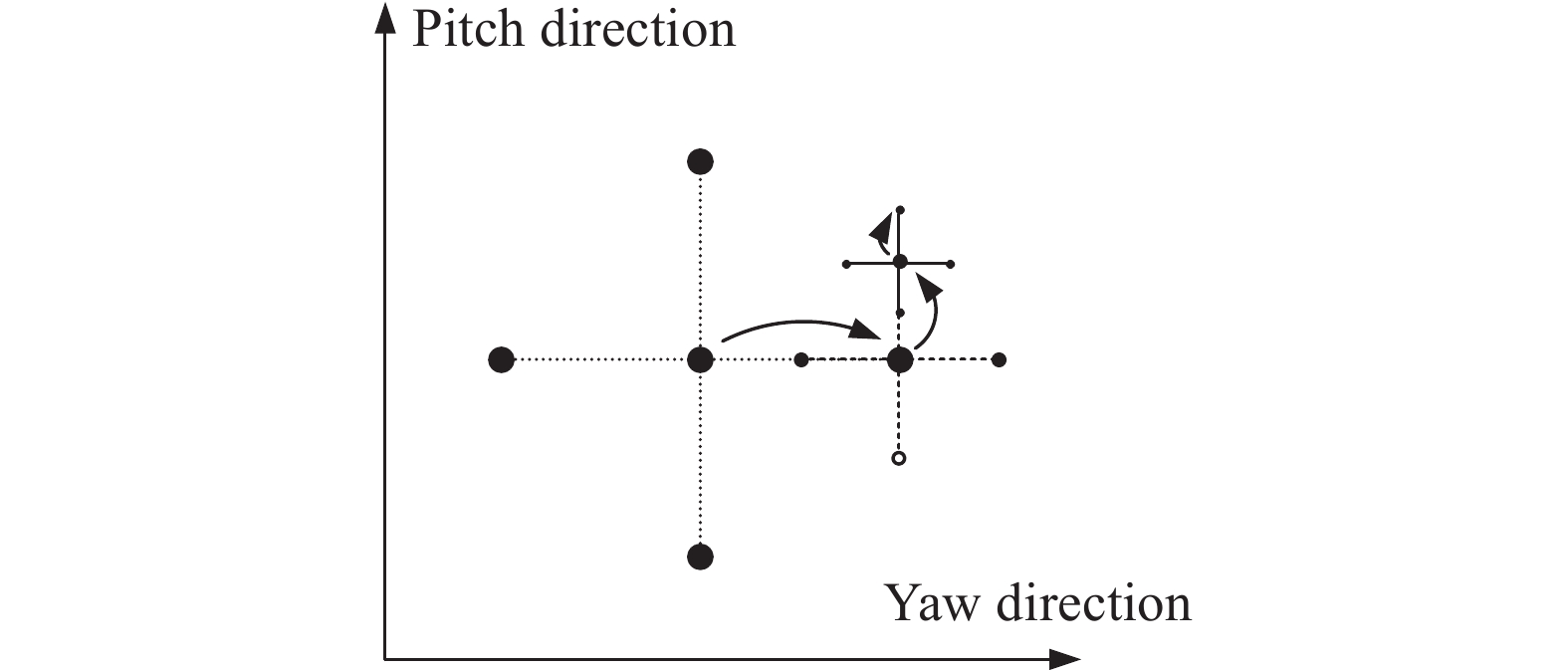
图 4 重合点搜索方法
Figure 4. Coincidence point search method
首先,根据相机的安装情况,确定理想的重合点位置$ \left(\begin{array}{cc}{\theta }_{PITCH-0},& {\theta }_{YAW-0}\end{array}\right) $,即认为转台在该点的方位角$ {\theta }_{YAW-0} $和俯仰角$ {\theta }_{PITCH-0} $示值下,绕横滚轴旋转一圈,相机的成像位置在一点不动。(但是,由于光轴与转台旋转轴存在安装误差,成像位置会构成一个圈)在理想重合点位置的基础上,估计出实际重合点轴线与理想轴线的最大夹角$ {\theta }_{MAX} $。基于此,对理想重合点以及其正四邻域距离为$ {\theta }_{MAX} $的一共5个点分别进行测试,测试这些位置处横滚轴转一圈成像位置形成的闭合圆或封闭曲线的平均直径的大小(为了简化起见,可用横滚角在0°、90°、180°、270°这4个数值的位置进行估计)。找出其中最小直径圆所对应的点,并以最小值对应的点作为中心,连同其正四邻域的点一并进行下一轮的估计。此时邻域的步长缩短为前一次的1/2。如此以往,直到前后两次搜索中曲线平均直径的变化率小于一定阈值,搜索结束。从而得到了真实的重合点位置$ \left(\begin{array}{cc}{\widehat{\theta }}_{PITCH-0},& {\widehat{\theta }}_{YAW-0}\end{array}\right) $。自此,认定在真实重合点位置处,转台横滚轴与入射平行光重合。
-
将第一步搜索到的重合点作为圆心,固定转台方位轴角度,控制转台俯仰轴生成等间隔的$ M $个径向夹角,在每个径向夹角下控制横滚轴绕360°一周等间隔生成$ N $个切向方位角,最终产生$ M\times N $个采样点集合。需要注意的是,采样过程中需要保持转台俯仰及横滚轴始终向同一方向运动以减小回程误差。详细采样点分布如图5所示。

图 5 径向采样点分布
Figure 5. Radial sampling point distribution
-
同样地,将第一步搜索到的重合点位置作为零点,利用方位轴和俯仰轴分别在水平和垂直方向上形成等间隔的栅格采样点。采样时,转台横滚角保持0°不变,栅格点采样按照Z字形的顺序进行,以减少累积误差。详细采样点分布如图6所示。

图 6 栅格采样点分布
Figure 6. Raster sampling point distribution
-
径向标定是建立像素坐标$ (u,v) $与入射矢量的径向夹角及切向方位角$ (\theta ,\alpha ) $之间的映射关系。具体分为如下4个步骤:
1)主点的建立,对于标定中每一个转台俯仰角$ {\theta }_{PITCH-k},k\in M $情形下采集的整圈质心位置$ \left\{\left({u}_{jk},{v}_{jk}\right)\right\}, j\in [1,N] $进行对称中心$ \left({u}_{0 k},{v}_{ok}\right) $的求解。在整圈采样点为偶数的情况下,则可以简单地利用下式求解:
$$ \left({u}_{0k},{v}_{0k}\right)=\frac{1}{N}\sum _{j=1}^{N}\left({u}_{jk},{v}_{jk}\right) $$ (1) 进一步地,对于各圈的对称中心进行平均,得到主点的估计值:
$$ \left({u}_{0},{v}_{0}\right)=\frac{1}{M}\sum _{k=1}^{M}\left({u}_{0k},{v}_{0k}\right) $$ (2) 显然,由于相机光轴和转台横滚轴的安装误差,这个估计值并不准确,但这不妨碍计算的进一步进行。
2)平均径向距离与径向夹角关系的建立,在上一步的基础上,对于每圈采样点中每一个固定俯仰角$ {\theta }_{PITCH-k} $情形下采集的整圈质心位置$ \left\{\left({u}_{jk},{v}_{jk}\right)\right\}, j\in [1,N] $可以求解圈上各采样点对应的像素坐标与主点间的欧式距离:
$$d_{j k}=\left\|\left(u_{j k}-u_0, v_{j k}-v_0\right)\right\| $$ (3) 而对于每圈转台俯仰角$ {\theta }_{PITCH-k} $的平均径向距离为:
$$ {d}_{k}=\frac{1}{N}\sum _{j=1}^{N}{d}_{jk} $$ (4) 则据此可以利用三次样条插值建立平均径向距离与入射夹角正切值之间的映射关系为:
$$ \left({d}_{k}\sim \mathrm{t}\mathrm{a}\mathrm{n}{\theta }_{k}\right) $$ (5) 3)方位角平均偏差的确定,对于每一个成像位置$ \left({u}_{jk},{v}_{jk}\right) $可以通过下式求出其成像时的方位角:
$$ {\alpha }_{jk}=\mathrm{a}\mathrm{r}\mathrm{c}\mathrm{t}\mathrm{a}\mathrm{n}\left({u}_{jk},{v}_{jk}\right) $$ (6) 与此同时,转台横滚轴产生的方位角参考值为$ {\theta }_{ROLL-j} $,则成像位置方位角与参考值的平均偏差为:
$$ \Delta \overline{\alpha }=\sum _{k=1}^{M}\sum _{j=1}^{N}\left({\alpha }_{jk}-{\theta }_{ROLL-j}\right) $$ (7) 4)质心误差映射关系的建立。根据第2)至3)步骤可知,除各个采样点处少量的质心位置偏差外,基本满足径向距离与径向夹角的映射关系以及方位角的偏差约束。为此,通过上述关系算出没有质心位置偏差的情况下,不同标定点理论的成像位置 ,则可以建立标定点实际成像位置与理论成像位置修正量的映射关系:
$$ \left({u}_{jk},{v}_{jk}\right)\sim \left({\overline{u}}_{jk}-{u}_{jk},{\overline{v}}_{jk}-{v}_{jk}\right) $$ (8) -
栅格补偿,旨在消除标定过程中光轴指向与转台横滚轴指向不重合引起的系统误差,如图7所示。

图 7 光轴与横滚轴不重合示意
Figure 7. The indication that the optical axis does not coincide with the rolling axis
假定光轴在转台横滚轴建立的径向坐标系下的切向方位角为$ \alpha $,径向夹角为$ \theta $。由于光轴与转台回转轴不重合,故存在一个2自由度的旋转安装误差,该安装误差可以分解成为绕转台俯仰轴和方位轴的两个角度量$ {\theta }_{Y0} $和$ {\theta }_{X0} $。忽略方位角零位,计算出转台坐标系与相机坐标系间的旋转矩阵$ {R}_{ROT2 CAM} $:
$$ {R}_{ROT2CAM}={R}_{X}\left({\theta }_{X0}\right)\times{R}_{Y}\left({\theta }_{Y0}\right) $$ (9) 式中:$ {R}_{Y} $是绕转台俯仰轴的旋转矩阵;$ {R}_{X} $是绕转台方位轴的旋转矩阵。
根据已知入射矢量方向在转台极坐标系下的表示 $ (\theta ,\alpha ) $,可以得到该矢量方向在转台直角坐标系下的表示$ \mathit{v} $:
$$ \mathit{v}=\left(\begin{array}{c}\mathrm{sin}\theta \; \mathrm{cos}\alpha \\ \mathrm{sin}\theta \;\mathrm{sin}\alpha \\ \mathrm{cos}\theta \end{array}\right) $$ (10) 将其转换到相机坐标系下:
$$ {\mathit{v}}^{\mathit{{'}}}=\left(\begin{array}{c}\mathrm{sin}\theta {'} \; \mathrm{cos}\alpha {'}\\ \mathrm{sin}\theta {'}\;\mathrm{sin}\alpha {'}\\ \mathrm{cos}\theta {'}\end{array}\right) = {R}_{ROT2CAM}\times\mathit{v} $$ (11) 式中:$ {\alpha }{{'}},\theta {'} $分别是补偿安装误差后的切向方位角和径向夹角。
利用三角函数进一步可得:
$$ \left\{\begin{array}{c}{\theta }{'}=\arccos\left(\mathrm{c}\mathrm{o}\mathrm{s}{\theta }_{Y0}\mathrm{c}\mathrm{o}\mathrm{s}{\theta }_{X0}\mathrm{c}\mathrm{o}\mathrm{s}\theta -\mathrm{s}\mathrm{i}\mathrm{n}{\theta }_{X0}\mathrm{s}\mathrm{i}\mathrm{n}\theta \right)\\ {\alpha }{'}=\alpha +\arctan \left(\dfrac{\mathrm{c}\mathrm{o}\mathrm{s}{\theta }_{X0}\mathrm{s}\mathrm{i}\mathrm{n}\theta +\mathrm{c}\mathrm{o}\mathrm{s}{\theta }_{Y0}\mathrm{s}\mathrm{i}\mathrm{n}{\theta }_{X0}\mathrm{c}\mathrm{o}\mathrm{s}\theta }{-\mathrm{s}\mathrm{i}\mathrm{n}{\theta }_{X0}\mathrm{c}\mathrm{o}\mathrm{s}\theta }\right)\end{array}\right. $$ (12) 根据公式(12)及已知栅格标定点信息,可以对$ {\theta }_{Y0} $和$ {\theta }_{X0} $进行二维变步长搜索,直至找到精确的两轴安装误差角,搜索的损失函数可选用栅格标定点入射矢量解算的角距偏差的模之和。至此,利用栅格标定点得到了栅格补偿的解析关系$ \left(\theta {'},\alpha {'}\right)=f(\theta ,\alpha ) $。
总的标定流程如算法 1 所示。
算法1: 输入:转台三轴角度$ {\theta }_{YAW},{\theta }_{PITCH},{\theta }_{ROLL} $,相机像素坐标$ (u,v) $ 输出:补偿模型 步骤1:根据安装情况迭代变步长搜索标定重合点,使得转台回转轴与入射光轴平行。 步骤2:等角度间隔并以一定规律进行径向标定点的采集。 步骤3:等角度间隔并以一定规律进行栅格标定点的采集。 步骤4:利用三次样条曲线拟合出统一的径向模型,并使用欧式距离插值抑制切向误差以及相机的非对称性误差。 步骤5:依据栅格标定点并通过二维变步长搜索抑制转台回转轴与相机光轴不平行引入的系统误差。 算法1结束 -
根据径向标定的处理结果,通过已知成像点像素坐标$ ({u}_{p},{v}_{p}) $,先根据实际成像位置与理论成像像素坐标补偿量之间的映射关系,即公式(8),求得成像点经过径向标定补偿后的粗略像素坐标,随后根据公式(12)进行系统误差修正。补偿流程如算法2所示。
算法2: 输入:像素坐标$ ({u}_{p},{v}_{p}) $ 输出:入射矢量在相机坐标系下的表示$ {\mathit{v}}_{c} $ 步骤1:计算出成像点对应入射矢量的大致径向夹角以及切向方位角(公式(5)、(7)) 。 步骤2:搜索与之相邻两圈标定点的径向夹角。 步骤3:搜索与之相邻两个控制点的切向方位角。 步骤4:根据步骤2估计的两个径向夹角和步骤3确定的两个切向方位角,可以得到将成像点包围的4个控制点。 步骤5:计算得到该成像点的理论成像位置。并进一步地计算得到入射矢量的径向夹角和切向方位角(公式(5)、(7)、(8))。 步骤6:将步骤5得到的结果进行系统误差的修正,返回入射矢量在相机坐标系下的表示$ {\mathit{v}}_{c} $(公式(12))。 算法2结束 -
为了验证文中方法的有效性,文中首先构建多种虚拟模型并采用多种标定方法进行仿真实验,分析不同标定方法对于不同虚拟模型标定结果的精度指标。随后搭建真实的鱼眼相机进行标定,验证文中方法在实际应用中的标定效果。
-
首先根据4种经典鱼眼成像模型分别构建4种理想的鱼眼相机模型。随后在理想模型的基础上加入主点偏移、切向畸变、镜头非对称性等因素带来的干扰以模拟真实的鱼眼相机,对相机加入三轴旋转来模拟安装误差的影响。
生成的4种虚拟鱼眼相机参数如表1所示,视场之所以设置为160°是因为正交投影的视场角不能超过180°
由于准直测量这一应用场景与计算机视觉、增强现实等的区别较大,因此,并未采用传统的PSNR、SSIM等指标来对比标定方法的有效性及精度,而是采用了MRE进行对比。
表 1 虚拟鱼眼相机模型参数
Table 1. Model parameters of virtual fisheye camera
Reference projection relationship Equidistance projection Equisolid projection Stereographic projection Orthogonal projection FOV 160° 160° 160° 160° Focal length 3.82 4.11 4.06 3.94 Image size/pixel 2 048(H)
2 048(V)2 048(H)
2 048(V)2 048(H)
2 048(V)2 048(H)
2 048(V)Principal point coordinate 1015.33(H)
992.64(V)1037.58(H)
1019.23(V)1023.04(H)
1023.59(V)1020.98(H)
1029.30(V)First order tangential distortion parameter $ 6.37\times 1{0}^{-5} $ $ 3.64\times 1{0}^{-5} $ $ -2.71\times 1{0}^{-5} $ $ 4.19\times 1{0}^{-5} $ Second order tangential distortion parameter $ 4.49\times 1{0}^{-6} $ $ -1.54\times 1{0}^{-5} $ $ 9.44\times 1{0}^{-6} $ $ 1.02\times 1{0}^{-5} $ 将文中方法于其他3种不同的标定方法[2,7-8]用于生成的4种虚拟鱼眼相机模型,并使用若干组坐标已知的参考物-像点对验证这些标定方法(每种相机模型各1600组)。针对同一种模型生成的参考物-像点对,分别计算每种标定方法对应于该种虚拟鱼眼相机模型的平均重投影误差,重复上述流程直至4种相机模型全部完成计算。对比结果如图8所示。

图 8 不同方法的标定效果比较
Figure 8. Comparison of calibration effects of different methods
分析图8中的标定结果, Brousseau等人的方法对于前述4种虚拟相机的标定的重投影误差最大不高于0.071 pixel,效果较好。但是由于使用了视场拼接技术,多个视场重合部分的合并映射过程会引入较大误差,特别是在重合部分区域更靠近边缘视场的情况下会产生更大的误差;就基于等距投影模型的虚拟相机而言,Feng等人的方法在其上的标定结果优于文中方法,是因为该方法是基于理想的等距投影模型提出的,也正因为此,该方法在其他3种虚拟相机模型下的标定重投影误差较文中方法均至少增加19.27%;Cai等人的方法在拍摄条纹图像的过程中,由于使用的是平面显示器,导致条纹图像不能完全覆盖全部视场,尤其无法覆盖边缘视场。并且,鱼眼相机的畸变程度随着像点靠近视场边缘而逐渐加剧,畸变程度越深对标定结果的影响越剧烈。最终导致边缘视场的重投影误差较大,从而降低全视场的整体标定精度;文中方法保证了全视场范围标定的连贯性,因此文中方法在4种不同的虚拟鱼眼相机的标定上的平均重投影误差均能保持在0.06 pixel以下。
-
制作了一个基于嵌入式平台的鱼眼相机用以验证我们的标定方法,该鱼眼相机的具体参数如表2所示。
表 2 鱼眼相机参数
Table 2. Parameters of fisheye camera
Processor XC7Z035 Image sensor GSENSE2020BSI Image format 12 bit gray Image size/pixel ${2\;048}\left({H}\right)\times {2\;048}\left({ { {V} } }\right)$ Pixel size $6.5\;\text{μ}\text{m}\times 6.5\;\text{μ}\text{m}$ Lens FOV 210° Equivalent focal length $\text{4 mm }$ Camera FOV $\text{18}{\text{0} }^{\circ }\left({H}\right)\times \text{18}{\text{0} }^{\circ }\left({V}\right)$ 首先尝试采用4种经典鱼眼相机模型对真实鱼眼相机进行标定,以2°作为径向步长,4°为切向步长进行径向标定点的采集,径向标定点的采集覆盖180°范围的圆周视场。标定结果如图9所示。

图 9 经典模型标定误差分布。(a)立体视角投影模型标定误差分布;(b) 正交投影模型标定误差分布;(c) 等立体角投影模型标定误差分布;(d)等距投影模型标定误差分布
Figure 9. Calibration error distribution of 4 classical camera model. (a) Stereographic projection model calibration error distribution; (b) Orthogonal projection model calibration error distribution; (c) Equisolid projection model calibration error distribution; (d) Equidistance projection model calibration error distribution
从图9可以看出,文中使用的真实鱼眼相机的投影模型与等立体角投影模型近似,但是并未完全遵循该投影模型,因此标定结果存在低频误差,并且由于镜片加工和装调等不确定因素,导致整体误差分布并不关于中心对称。另外,图像中心区域也存在不小的标定误差,经过分析,可能是由于标定点采集过程中3个标定轴向两两之间相互不重合所导致。从整体上看,标定结果的径向误差随着视场角的增加存在着增大的趋势,这是由于鱼眼相机的畸变随着视场角的增加逐渐剧烈。因此,径向重投影误差是鱼眼相机标定中最主要的误差源。
随后采用文中提出的方法流程进行标定,将鱼眼相机安装在高精度三轴转台上,首先根据2.1小节所描述的方法进行重合点的搜索。随后以搜索到的重合点作为径向标定原点,并按照2.2小节描述的方法以2°作为径向步长,4°为切向步长进行径向标定点的采集,径向标定点的采集覆盖180°范围的圆周视场。之后同样以搜索到的重合点为中心作为栅格标定原点,按照2.3小节描述的方法以1°为水平和垂直步长进行栅格标定点的采集。栅格标定点的采集覆盖30°范围的方形中心视场。最终标定结果如图10所示。

图 10 文中方法标定结果
Figure 10. Calibration results of proposed method
图10为重投影误差的分布图。使用文中方法标定的鱼眼相机模型,其重投影误差最大值为0.16 pixel,最小值为0.05 pixel,误差分布均匀,精度较高。将重投影误差换算成矢量解算误差,此次标定的最大误差为0.0162°,平均误差为0.0121°,这说明了文中提出的准直测量用鱼眼相机标定方法的有效性。
为了进一步验证文中方法的有效性,使用标定完成的样机进行了外场实验,如图11所示。首先拍摄太阳并解算太阳矢量在地固坐标系下的表示以获得太阳观测矢量,然后利用Stellarium软件得到拍摄时刻当地坐标下太阳的真实俯仰角和方位角并计算出太阳参考矢量,最后对观测矢量和参考矢量进行比较可以计算出矢量解算误差。经过不同时刻的多次测量,样机的平均矢量解算误差为0.0152°。

图 11 外场实验
Figure 11. Outfield experiment
-
文中提出了一种准直测量用鱼眼相机标定方法。该方法将准直测量用鱼眼相机的标定流程分解为径向标定和栅格标定两部分,首先借助高精度转台和平行光管配合完成两种标定样本点的采集,随后使用径向标定完成成像模型的粗略构建,最后采用栅格标定消除径向标定中回转轴与光轴不重合造成的误差,进一步提高标定精度。经过仿真对比实验以及样机验证实验,证实文中方法可以应用于任意视场角的各类准直测量用鱼眼相机的高精度标定,能够为未来准直测量的发展提供技术支持。
Calibration method of fisheye camera for high-precision collimation measurement
-
摘要: 为了扩展准直测量的应用领域,提高测量范围是最为有效的手段之一,因此用于准直测量的鱼眼相机应运而生。针对准直测量用鱼眼相机标定精度不高的问题,提出了一种基于插值形式的径向粗标定及基于栅格形式的补偿精标定的两步式准直测量用鱼眼相机标定方法。该方法使用插值而并非构建成像模型,能够有效避免模型不准确及参数设置不合理而引入的系统误差,并且可以在一定程度上抑制镜片加工的非对称性及光学系统装调所带来的偏差。区别于图像评价的峰值信噪比(PSNR)以及结构相似性(SSIM)等性能指标,该方法选择的平均重投影误差(MRE)这一指标能够更有效地衡量准直测量使用条件下相机标定结果的优劣。仿真对比实验结果表明该方法在4种虚拟鱼眼相机模型上的标定效果皆优于传统标定方法,与传统的方法相比,标定的不确定度最大能够改善82.63%。样机标定实验结果表明,该方法能够有效标定真实的准直测量用鱼眼相机,在搭建的真实样机上应用该标定方法后,样机的入射矢量解算的不确定度能够提升至角秒级。Abstract:
Objective Collimation measurement is one of the most widely used precision angle measurement and attitude measurement methods. By imaging the known reference target at infinity, the accurate angular relationship between the measured object and the reference target can be obtained. The measurement results have the advantages of high accuracy and high repeatability. Photoelectric autocollimator, electronic total station, theodolite and other measuring and calibration instruments all take collimation measurement as their main measurement principle. Due to the limitation of the calibration accuracy of the large-field-of-view and high-distortion optical system, the camera field of view used in precision collimation measurement is usually small, so there are great limitations in the application of large range angle measurement. Fisheye camera has the advantages of large field of view, small volume and light weight, so it should have a broad development prospect in the field of measurement and calibration. However, due to the large field of view and large distortion of the fisheye camera, there is a complex nonlinearity in the camera imaging process, and the asymmetry in lens processing has a more severe impact on the imaging model parameters. For this reason, a fisheye camera calibration method for high precision collimation measurement is proposed in this paper. Methods A two-step fisheye camera calibration method for collimation measurement is proposed in this paper, which includes radial rough calibration based on interpolation and fine calibration based on grid compensation. This method uses interpolation instead of constructing camera model, which can effectively avoid the system error caused by inaccurate model and unreasonable parameter setting, and can restrain the asymmetry of lens processing and the deviation caused by optical system adjustment to a certain extent. Different from the commonly used performance indicators such as peak signal-to-noise ratio (PSNR) and structural similarity (SSIM), the mean reprojection error (MRE) selected in this paper can more effectively measure the camera calibration results under the condition of collimation measurement. Results and Discussions According to the classical model of fisheye camera, four different virtual fisheye cameras are constructed for simulation experiments (Tab.1). The simulation result shows that the calibration effect of this method on the four virtual fisheye camera models is better than the calibration method proposed recently (Fig.8), and the calibration uncertainty can be increased by 82.63% compared with the traditional method. Then, a fisheye camera calibration prototype based on embedded platform is designed (Tab.2). The calibration experimental results of the prototype shows that the proposed method can effectively calibrate the real fisheye camera for collimation measurement (Fig.10). After the calibration method is applied to the real prototype built in this paper, the uncertainty of the solution of the incident vector of the prototype can be raised to arcseconds (Fig.11). Conclusions A fisheye camera calibration method for high-precision collimation measurement is proposed. In the method, calibration process of fisheye camera for collimation measurement is divided into two parts of radial calibration and grid calibration. Firstly, two kinds of calibration sample points are collected with the help of high-precision turntable and collimator. Then the rough construction of the imaging model is completed by radial calibration. Finally, grid calibration is used to eliminate the error caused by the non-coincidence of rotation axis and optical axis in radial calibration, and further improve the calibration accuracy. Through simulation comparison experiments and prototype verification experiments, it is proved that this method has high calibration accuracy. Moreover, this method can be applied to the high-precision calibration of all kinds of real fisheye cameras for collimation measurement, and can provide technical support for the development of collimation measurement in the future. -
Key words:
- collimation measurement /
- fisheye camera /
- calibration /
- distortion correction
-
图 3 准直测量用鱼眼相机标定装置示意图
Figure 3. Calibration device of collimation measurement fisheye camera
图 7 光轴与横滚轴不重合示意
Figure 7. The indication that the optical axis does not coincide with the rolling axis
图 9 经典模型标定误差分布。(a)立体视角投影模型标定误差分布;(b) 正交投影模型标定误差分布;(c) 等立体角投影模型标定误差分布;(d)等距投影模型标定误差分布
Figure 9. Calibration error distribution of 4 classical camera model. (a) Stereographic projection model calibration error distribution; (b) Orthogonal projection model calibration error distribution; (c) Equisolid projection model calibration error distribution; (d) Equidistance projection model calibration error distribution
算法1: 输入:转台三轴角度$ {\theta }_{YAW},{\theta }_{PITCH},{\theta }_{ROLL} $,相机像素坐标$ (u,v) $ 输出:补偿模型 步骤1:根据安装情况迭代变步长搜索标定重合点,使得转台回转轴与入射光轴平行。 步骤2:等角度间隔并以一定规律进行径向标定点的采集。 步骤3:等角度间隔并以一定规律进行栅格标定点的采集。 步骤4:利用三次样条曲线拟合出统一的径向模型,并使用欧式距离插值抑制切向误差以及相机的非对称性误差。 步骤5:依据栅格标定点并通过二维变步长搜索抑制转台回转轴与相机光轴不平行引入的系统误差。 算法1结束  下载: 导出CSV
算法2: 输入:像素坐标$ ({u}_{p},{v}_{p}) $ 输出:入射矢量在相机坐标系下的表示$ {\mathit{v}}_{c} $ 步骤1:计算出成像点对应入射矢量的大致径向夹角以及切向方位角(公式(5)、(7)) 。 步骤2:搜索与之相邻两圈标定点的径向夹角。 步骤3:搜索与之相邻两个控制点的切向方位角。 步骤4:根据步骤2估计的两个径向夹角和步骤3确定的两个切向方位角,可以得到将成像点包围的4个控制点。 步骤5:计算得到该成像点的理论成像位置。并进一步地计算得到入射矢量的径向夹角和切向方位角(公式(5)、(7)、(8))。 步骤6:将步骤5得到的结果进行系统误差的修正,返回入射矢量在相机坐标系下的表示$ {\mathit{v}}_{c} $(公式(12))。 算法2结束
下载: 导出CSV
表 1 虚拟鱼眼相机模型参数
Table 1. Model parameters of virtual fisheye camera
Reference projection relationship Equidistance projection Equisolid projection Stereographic projection Orthogonal projection FOV 160° 160° 160° 160° Focal length 3.82 4.11 4.06 3.94 Image size/pixel 2 048(H)
2 048(V)2 048(H)
2 048(V)2 048(H)
2 048(V)2 048(H)
2 048(V)Principal point coordinate 1015.33(H)
992.64(V)1037.58(H)
1019.23(V)1023.04(H)
1023.59(V)1020.98(H)
1029.30(V)First order tangential distortion parameter $ 6.37\times 1{0}^{-5} $ $ 3.64\times 1{0}^{-5} $ $ -2.71\times 1{0}^{-5} $ $ 4.19\times 1{0}^{-5} $ Second order tangential distortion parameter $ 4.49\times 1{0}^{-6} $ $ -1.54\times 1{0}^{-5} $ $ 9.44\times 1{0}^{-6} $ $ 1.02\times 1{0}^{-5} $
下载: 导出CSV
表 2 鱼眼相机参数
Table 2. Parameters of fisheye camera
Processor XC7Z035 Image sensor GSENSE2020BSI Image format 12 bit gray Image size/pixel ${2\;048}\left({H}\right)\times {2\;048}\left({ { {V} } }\right)$ Pixel size $6.5\;\text{μ}\text{m}\times 6.5\;\text{μ}\text{m}$ Lens FOV 210° Equivalent focal length $\text{4 mm }$ Camera FOV $\text{18}{\text{0} }^{\circ }\left({H}\right)\times \text{18}{\text{0} }^{\circ }\left({V}\right)$
下载: 导出CSV
-
[1] Chen Wenyi, Xu Jie, Yang Hui. Camera calibration method based on double neural network [J]. Infrared and Laser Engineering, 2021, 50(11): 20210071. (in Chinese) doi: 10.3788/IRLA20210071 [2] Yang S R, Lin C Y, Liao K, et al. FishFormer: Annulus slicing-based transformer for fisheye rectification with efficacy domain exploration [DB/OL]. (2023-07-05) [2023-08-01].https://arxiv.org/abs/2207.01925 . [3] Rong J P, Huang S Y, Shang Z Y, et al. Radial lens distortion correction using convolutional neural networks trained with synthesized images [C]//Asian Conference on Computer Vision (ACCV), 2016: 35–49. [4] Chao C H, Hsu P L, Lee H Y, et al. Self-supervised deep learning for fisheye image rectification [C]//International Conference on Acoustics, Speech, and Signal Processing (ICASSP), 2020: 2248–2225. [5] Camposeco F, Sattler T, Pollefeys M. Non-parametric structure-based calibration of radially symmetric cameras [C]// International Conference on Computer Vision (ICCV), 2015: 2192-2200. [6] Ramalingam S, Sturm P. A unifying model for camera calibration [J]. Transactions on Pattern Analysis and Machine Intelligence, 2017, 39(7): 1309-1319. doi: 10.1109/TPAMI.2016.2592904 [7] Wei Boyan, Tian Qingguo, Ge Baozhen. Camera calibration based on color-coded phase-shifted fringe [J]. Opto-Electronic Engineering, 2021, 48(1): 200118. [8] Tezaur R, Kumara, Nestares O. A new non-central model for fisheye calibration [C]//Conference on Computer Vision and Pattern Recognition Workshops (CVPRW), 2022: 5218-5127. [9] Cai C T, Qiao R J. An improved calibration method for stereo fisheye vision [C]//Chinese Control and Decision Conference (CCDC), 2021: 3158-3162. [10] López-Antequera M, Marí R, Gargallo P, et al. Deep single image camera calibration with radial distortion [C]//Conference on Computer Vision and Pattern Recognition (CVPR), 2019: 11809-11817. [11] Ao Naixiang, Li Hao, Wang Deyong. ICP and -regression based fisheye calibration estimation l1 [J]. Journal of CAEIT, 2017, 12(1): 67-72, 110. [12] Feng Weijia, Zhang Baofeng, Cao Zuoliang. Omni-directional vision parameter calibration and rectification based on fish-eye lens [J]. Journal of Tianjin University (Science and Technology), 2011, 44(5): 417-424. [13] Xue Z C, Xue N, Xia G S, et al. Learning to calibrate straight lines for fisheye image rectification [C]//Computer Vision and Pattern Recognition (CVPR), 2019: 1643-1651. [14] Yin X Q, Wang X C, Yu, J, et al. FishEyeRecNet: A multi-context collaborative deep network for fisheye image rectification [C]//European Conference on Computer Vision (ECCV), 2018: 11214. [15] Li W H, Qu Y, Wang Y, et al. Robust distortion estimation of fisheye cameras under stereographic projection model [C]// Intelligent Systems and Knowledge Engineering (ISKE), 2019:1017-1024. [16] Wakai N, Sato S, Ishii Y, et al. Rethinking generic camera models for deep single image camera calibration to recover rotation and fisheye distortion [C]//European Conference on Computer Vision (ECCV), 2022: 13678. [17] Cai J, Yang K, Cheng L, et al. Pixel-wise fisheye image correction method with single-view phase target [J]. Photonics Technology Letters, 2022, 34(19): 1038-1041. doi: 10.1109/LPT.2022.3199616 [18] Brousseau P A, Roy S. Calibration of axial fisheye cameras through generic virtual central models [C]//International Conference on Computer Vision (ICCV), 2019: 4039-4047. -

 点击查看大图

计量
- 文章访问数: 96
- HTML全文浏览量: 29
- PDF下载量: 33
- 被引次数: 0

