


-
目前,水下光通信技术主要采用激光LD和LED为发射光源,海水对400~500 nm波段的蓝光吸收最小,这使得基于蓝光LED水下通信系统性能的研究迅速成为热点。2013年G.Cossu 和S.Balestrino等研究人员完成了2.5 m、12.5 Mbps、OOK调制的LED 水下光通信系统[1]。2016年Mohammed Al-Rubaiai等研究人员实现了23 m、115.2 Kbps、OOK调制的蓝光LED水下光通信系统[2]。近两年来,为了克服普通LED调制速率较低的特点,众多学者展开了先进调制格式的研究。2018年,Wang Peilin等研究人员采用OOK调制方式使蓝色LED通信速率达到0.025 Gb/s,通信距离为10 m[3];Chi Nan等研究人员采用PAM8调制方式使蓝色LED通信速率达到1.5 Gb/s,通信距离为1.2 m[4];同年Chi Nan等研究人员利用CAP64-OFDM调制技术将蓝色LED的通信速率提升到3 Gb/s,其通信距离为1.2 m[5];Wang Fumin等研究人员采用64QAM-DMT调制技术将绿色LED的通信速率达到2.175 Gb/s,通信距离为1.2 m[6];Meng Shi等研究人员采用MISO PAM7调制技术,使LED通信速率达到0.92 Gb/s,通信距离为2.1 m[7];2019年Chen Ming等研究人员采用DMT调制方式使蓝色LED通信速率达到2.34 Gb/s,通信距离为1.2 m[8]。
目前基于先进调制技术的水下光通信系统大多还处于实验室研究阶段,采用复杂调制模式可大幅提高通信速率,但其通信距离短,硬件实现复杂,成本较高,也不利于水下通信机的商用小型化。在水下无线光通信设备工程化方面,2017年P.Leon、F.Roland等学者基于LED及光电倍增管,采用OOK调制技术,研制的工程样机在浅海开展了测试,通信距离60 m时,通信速率达3 Mbps[9]。2018年中国科学院西安光学精密机械研究所基于LED的蓝光水下工程样机进行了海试,传输距离为20 m,速率为20 Mbps[10]。国内在水下光通信系统的工程化应用方面起步较晚,与国外差距较大,大多数研究是针对小功率LED水下光通信,但由于小功率LED发射功率小,通信距离短等特点,不适用工程光通信领域。文中基于OOK调制原理,利用分立元件搭建了大功率LED驱动电路,同时结合小功率LD通信高速率特点,设计出了双发射端及双接收端的水下光通信工程样机。该样机在发射端使用了大功率LED和小功率LD双发射光源,在接收端采用了APD和PMT双接收光信号,其中大功率LED,可选用PMT接收光信号,用于水下远距离低速率通信,小功率LD可选用APD接收光信号,用于水下近距离高速率通信。用户可根据通信距离的需求通过上位机对FPGA控制自由切换接收方式。经水下试验显示系统实现了稳定可靠的实时通信。
-
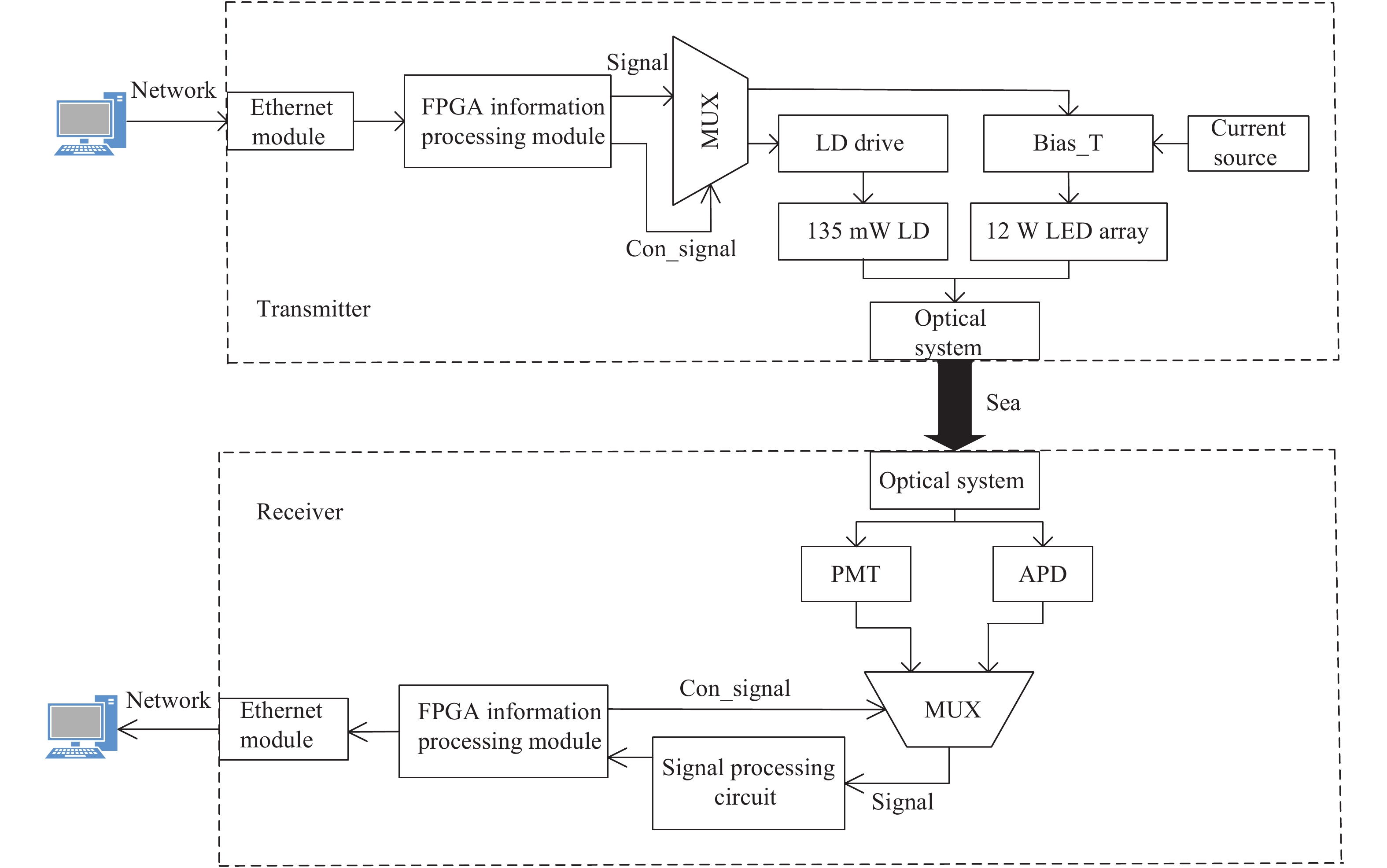
水下光通信系统整体结构如图1所示。系统由以太网模块、FPGA发送模块、数据选择器模块、激光发射模块、LED驱动模块、LED阵列模块、光电接收模块、光电转换模块、信号放大处理电路、FPGA接收模块、RS编解码模块和上位机组成。

Figure 1. Overall structure diagram of the system
以太网模块接收上位机以太网数据包,并由FPGA进行数据的内部缓存,通过内部RS纠错编码器、8B10B编码器进行编码,后经并串转换输出LVTTL电平信号,由FPGA输出控制信号控制数据选择器将TTL电平信号调制到LED驱动电路或者激光二极管驱动电路中,(其中LED驱动模块由Bias-T、恒流源电路和LED阵列构成)光源经过准直光学镜头发射进入水下信道。接收端光学系统包括滤光片、非球面接收镜头,接收光信号有PMT光电探测器和APD光电探测器两种方式选择,由FPGA控制选择接收光信号的探测器。将接收光信号进行光电转换后送给信号放大处理电路,得到LVTTL电平脉冲序列,再经FPGA接收模块解调和解码来恢复信息并经以太网模块送入上位机软件处理相关信息。
-
系统根据水下光通信系统中光源切换由FPGA控制,其中激光LD调制技术已非常成熟,文中重点介绍优化后的大功率LED信号调制硬件设计。OOK调制方式原理是利用传输信号的电平特性驱动LED光源开关,传统OOK调制电路对小功率光源驱动有良好的效果,大功率LED高速调制还存在很多难点。文中设计,利用大功率高速NMOS管承载高电压,大电流驱动LED光源,同时采用反馈控制电路能够准确设置驱动电流的数值,并对驱动电流进行实时监测与控制,使得LED光源能够输出恒定的平均光功率。优化后的大功率LED调制驱动电路电流-光功率曲线如图2所示。

Figure 2. LED digital modulation characteristic curve
通过反馈控制电路设置LED的阈值电流
${{I}_{{\rm{BIAS}}}} \approx $ $ {{I}_{{\rm{th}}}}$ ,推动LED的工作范围处于临界导通状态,利用数字调制信号的电流,控制LED产生不同大小的光功率变化。当调制信号发送数字信号“1”时,流经LED的电流为$({{I}_{{\rm{BIAS}}}}{\rm{ + }}{{I}_{{\rm{MOD}}}})$ ,对应的光功率为$({{P}_{{\rm{BIAS}}}} + {{P}_{{\rm{MOD}}}})$ ,当调制信号发送数字信号“0”时,流经LED的电流为${{I}_{{\rm{BIAS}}}}$ ,对应的平均光功率为${{P}_{{\rm{BIAS}}}}$ ,利用光电探测器探测不同信号的光功率,实现信号的传输。根据上述原理可利用恒流源设置偏置电流,将偏置电流的值设置为LED的阈值电流,使LED发出阈值电流对应的光功率,然后通过信号电平驱动高速开关的导通与截止,对LED进行调制。高速开关在导通与截止的瞬间会产生一个非常窄的尖峰脉冲。由于尖峰脉冲非常窄,在低速率通信中影响小,在百兆以上的通信速率中影响较大,可应用磁珠元件设计电路降低尖峰坡度。
该方式实现了调制输出光功率与输入信号波形基本同步,电路模型如图3所示,可通过MCU设置流过LED电流大小。传统OOK模式采用电阻调控小电流,文中设计利用单片机实时采样调制端的电流值,根据采样电流值由单片机判决输出控制电压值的大小,最终形成对调制电流控制,实现对大功率LED信号调制。在水下光通信工程应用对大功率LED需求较多,可应用该方式对LED发射电路进行设计。

Figure 3. Improved circuit model diagram
表1给出了传统OOK调制方式和优化后的OOK调制方式性能参数对比,在平均发光功率上提高了
${{P}_{{\rm{BIAS}}}}/2$ ,而且其误时隙率更小。Parameter TRAD_OOK IMP_OOK Average optical power ${ {P }_{ {\rm{MAX} } } }/2$ $({ {P }_{ {\rm{BIAS} } } } + { {P }_{ {\rm{MAX} } } })/2$ Bandwidth requirements R R Channel capacity $1/{\rm{\tau}} $ $1/{\rm{\tau}} $ Slot error rate $\dfrac{1}{2}\left\{ {1 - {\rm{erf} }\left(\dfrac{ {\sqrt { { {{P} }_{ {\rm{MAX} } } }/2{ {\rm{\sigma} } ^2} } } }{2}\right)} \right\}$ $\dfrac{1}{2}\left\{ {1 - {\rm{erf} }\left(\dfrac{ {\sqrt {({ { {P} }_{ {\rm{BIAS} } } } + { { {P} }_{ {\rm{MAX} } } })/(2{ {\rm{\sigma} } ^2)} } } }{2}\right)} \right\}$ Table 1. Comparison table of performance parameters between traditional OOK modulation mode and improved OOK modulation mode
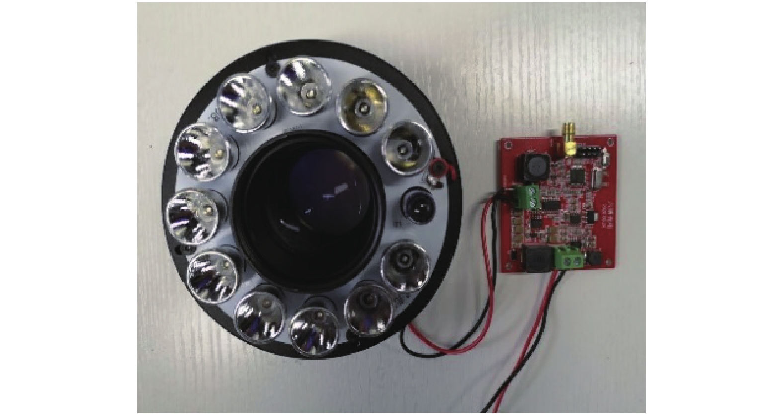
图4给出了大功率LED信号调制电路硬件实物图,发射端光源LED采用11个欧司朗LB H9GP蓝光组成阵列和欧司朗80 mW、450 nm激光二极管PL450B,串联成LED阵列,LED阵列功率约为33 W,驱动电压约为40 V,电流约为1 A。

Figure 4. Schematic diagram of high-power LED signal modulation circuit
选用调制端和偏置端NMOS管参数ID约为310 mA,在实验中将调制电流设置为216 mA,偏置电流设置为143 mA,流过LED的电流约为350 mA,如图5所示。在信号调制电路中,流过LED电流大小主要由调制器件NMOS管参数ID决定,若在电路设计中选择NMOS管参数ID>1000 mA,可使流过LED的电流达到1000 mA以上,实现对大功率LED的信号调制。

Figure 5. Measured value of the current flow through the LED
测试显示设计的LED阵列通信带宽为5 MHz,图6给出了其带宽测试图。当系统光源采用80 mW激光管时设计的大功率LED驱动调制电路带宽可达45 MHz。
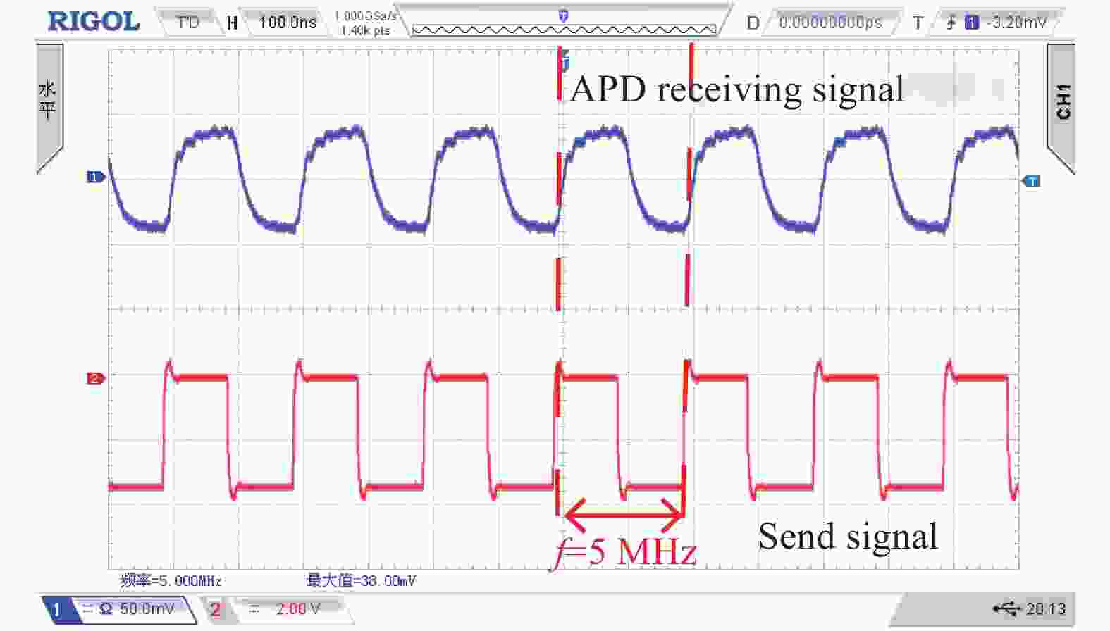
Figure 6. 5 MHz waveform of APD receiving communication bandwidth
-
系统接收端设计了APD和PMT两种接收器,接收示意图如图7所示。大面积(探测光敏直径5 mm)APD接收系统具有较大的接收视场;为系统提供了较大的动态范围,PMT接收系统具有较高的接收灵敏度(−60 dBm)利于进一步扩展系统的通信距离。
APD接收系统选用滨松S8664-50K雪崩光电二极管,峰值灵敏度波长为600 nm,光谱响应范围320~1000 nm,截止频率为60 MHz,感光面积为19.6 mm2,灵敏度16A/W,结合设计信号处理电路测试APD探测器灵敏度约为−31.3 dBm。
PMT接收系统选用滨松H14447光电倍增管,峰值灵敏度波长为450 nm,光谱响应范围为300~600 nm,感光面积156.25 mm2,灵敏度670 A/W,结合设计信号处理电路测试PMT灵敏度约为−55.6 dBm。

Figure 7. Schematic diagram of the receiving end of the system
通过搭建测试平台分别对接收端APD及PMT接收系统进行测试,图8和图9分别给出了两种接收系统的45 MHz的测试波形。

Figure 8. APD detector 45 MHz test output signal
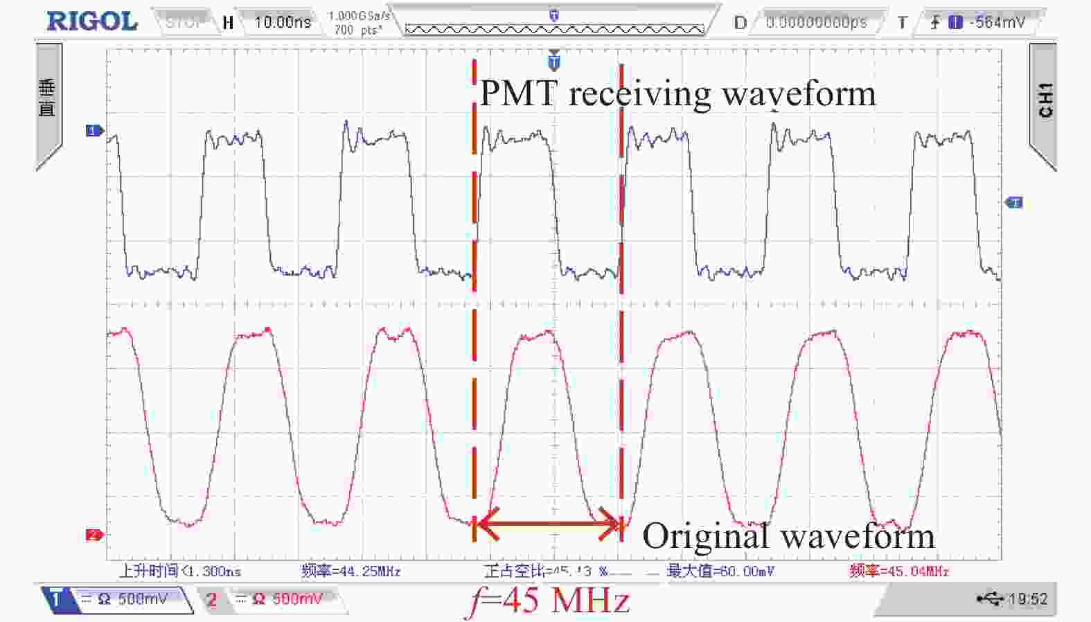
Figure 9. PMT detector 45 MHz test output signal
-
FPGA控制单元主要完成上位机通过网络通信方式发送的数据流进行接收,并对数据进行RS编码、8B/10B编码、并串转换等处理;然后将信号以TTL电平传输到LED驱动电路中。接收端FPGA将接收的TTL电平进行串并转换、8B/10B解码、RS解码等;将信息通过网络通信方式返回到接收端的上位机,结构框图如图10所示。因发射端和接收端通信时钟不可能完全同步,FPGA 控制核心设计了根据数据产生位同步的通信时钟,使接收端能够准确接收并采集发射端的数据。

Figure 10. FPGA control core block diagram
根据图10所示,对FPGA控制单元进行了编码和解码的软件仿真,实验结果表明设计的控制单元数据流可正常编解码及同步操作,满足了系统性能的需求,FPGA控制单元编解码数据流仿真结果如图11所示。其中图11显示数据流分别表示RS模块编码后输出数据流、8B/10B模块编码后输出数据流、发送信号、接收信号、8B/10B模块译码后输出数据流、RS模块译码后输出数据流,从图11中可以看出数据发射经过水下光信道后接收存在时延迟差,输入数据流与接收处理后的数据流存在延时状态,因此在FPGA中采用帧同步和位同步技术使接收的数据与发射的数据保持一致。

Figure 11. FPGA control unit encoding and decoding data flow
-
光信号在水下传输主要受到水的吸收特性和散射特性影响较大,同时与水下传输距离、收发角度等因素有密切关系,建立水下光通信链路模型如图12所示。

Figure 12. Underwater optical communication link model
设水下传输距离为d,光束发射半角为
$\gamma $ ,收发链路与光束中心轴线偏轴角为${\rm{\theta}}$ ,因此接收端接收光信号功率${{P}_{\rm{R}}}$ 可表示为[11]:式中:
${{P}_{\rm{T}}}$ 为平均发射光功率;${{\rm{\eta}} _{\rm{T}}}$ 为发射端光学效率;$ {{\rm{\eta}} }_{{\rm{R}}}$ 为接收端光学效率;${\rm{\varepsilon}} ({\lambda} )$ 为水的吸收衰减系数与散射衰减系数之和;${{S}_{\rm{R}}}$ 为接收端孔径面积。系统的误码率${{P}_{\rm{E}}}$ 可表示为[12]:式中:
${\eta} $ 为光电转换系数;${{N}_0}$ 为接收电路的热噪声密度,可表示为:式中:
${K}$ 为玻耳兹曼常数;T为开氏温度;B为接收机带宽;R为接收机阻抗。根据水下光通信链路模型可有效计算出系统理论接收光功率,分析误码率特性,与实际测试结果相对比。 -
根据图1的结构设计完成了水下光通信样机,并进行了长期的水密实验,工程样机如图13所示。

Figure 13. Engineering prototype
实验环境为深6 m、长20 m、宽8 m的立方体水池,注入极轻度浑浊的湖水来模拟大陆架的海水,湖水衰减因子约为0.24 dBm/m[13],通过光路设计完成通信距离的扩展,后期将在武汉东湖开展更为实际的测试工作,实验测试场景如图14所示。在水下光通信中,一般蓝绿光在水中衰减度较小,故设备分别采用中心波段为470 nm和520 nm的两种不同波段作为信号载体,进行水下信息交互通信,在水下测试距离约为16 m,通信速率为18 Mbps,图片信息传输完整。

Figure 14. Underwater experiment test scenario
由于设备在水下完全密封,无法准确测量系统的接收光功率、误码率等参数。测试系统一些性能参数在大气中进行,采用等效衰减方法,主要采用空间远距离通信和不同程度的光学衰减片模拟水下系统测试,如图15所示。

Figure 15. Simulating underwater test experiment
通过测试设备的发射光学系统损耗约为−1 dBm,接收光学系统损耗约为−4.3 dBm,根据参考文献[13]中提出大陆架的海水衰减约为0.44 dBm/m,对应衰减系数
${\rm{\varepsilon}} ({\lambda} )$ 约为0.12 m−1,水下设备无线光传输特性参数如表2所示。根据上述参数可计算出水下理论接收光功率,利用衰减片将通信光功率衰减到接近值,模拟水下通信距离,在该通信距离下测试其通信速率与误码率之间的关系,经过实验测试了在误码率小于10−7情况下,通信距离、通信速率、实际接收端光功率等参数如表3所示。
Parameter Value LED beam divergent half angle ${\rm{\gamma}} $/(°) 3.04 LD beam divergent half angle ${\rm{\gamma}} $/ (°) 0.51 LED optical transmitting power ${{P}_{\rm{T}}}$/ dBm 35.6 LD optical transmitting power ${{P}_{\rm{T}}}$/ dBm 18 Transmission link off-axis angle ${\rm{\theta }}$/ (°) 0 APD receiving area of photodetector ${ {S }_{\rm{R} } }$/${\rm{m}}{{\rm{m}}^2}$ 19.6π PMT receiving area of photodetector ${ {S }_{\rm{R} } }$/${\rm{m}}{{\rm{m}}^2}$ 156.25π Optical wavelength ${\lambda }$/nm 470 Table 2. Wireless optical transmission characteristic parameters of underwater equipment
Emission source Communication
distance/mCommunication
rate/MbpsReceiving
detectorTheoretical received optical
power value/dBmActual received
optical power/dBmLD 5 60 APD −10.09 −11.3 LD 10 60 APD −18.73 −18.5 LD 12 42 APD −21.35 −20.9 LED 20 18 APD −27.72 −28.2 LED 45 15 PMT −38.77 −38.6 LED 60 10 PMT −49.09 −53.2 Table 3. Equipment performance parameter test
同步测试了在不同距离下LED通信速率与误码率之间的关系,实验采用ET34A误码测试仪采集通信误码率(BER),在设备中FPGA采用8B/10B编码,因此测试中使用27-1码型,该误码分析仪通信速率最高可到34 Mbps。实验测试了通信距离分别为20、45、60 m的不同通信速率下误码率的大小,曲线如图16所示。

Figure 16. Bit error rate performance test of equipment
系统编写了上位机软件,外接高清摄像头对实时视频、图片及文字进行传输,通信系统两端 通过对以太网数据包数据进行分析通信系统可靠性。实验如图17所示,在1~60 m的通信距离范围,系统可实现了可靠的信息通信。以图片信息传输为例,当通信距离为10 m,通讯速率可达60 Mbps,图17中红色曲线表示实时显示的接收速率,当前接收速率60 Mbps,实时视频、图片、文字等信息传输完整。当通信距离为60 m,实时视频及图像文件在误码率10−7下,通讯速率可达10 Mbps。当通信距离大于60 m时,水下信道链路衰减逐步增大,系统误码率逐渐增大,这对接收端探测器灵敏度提出了更高的要求。
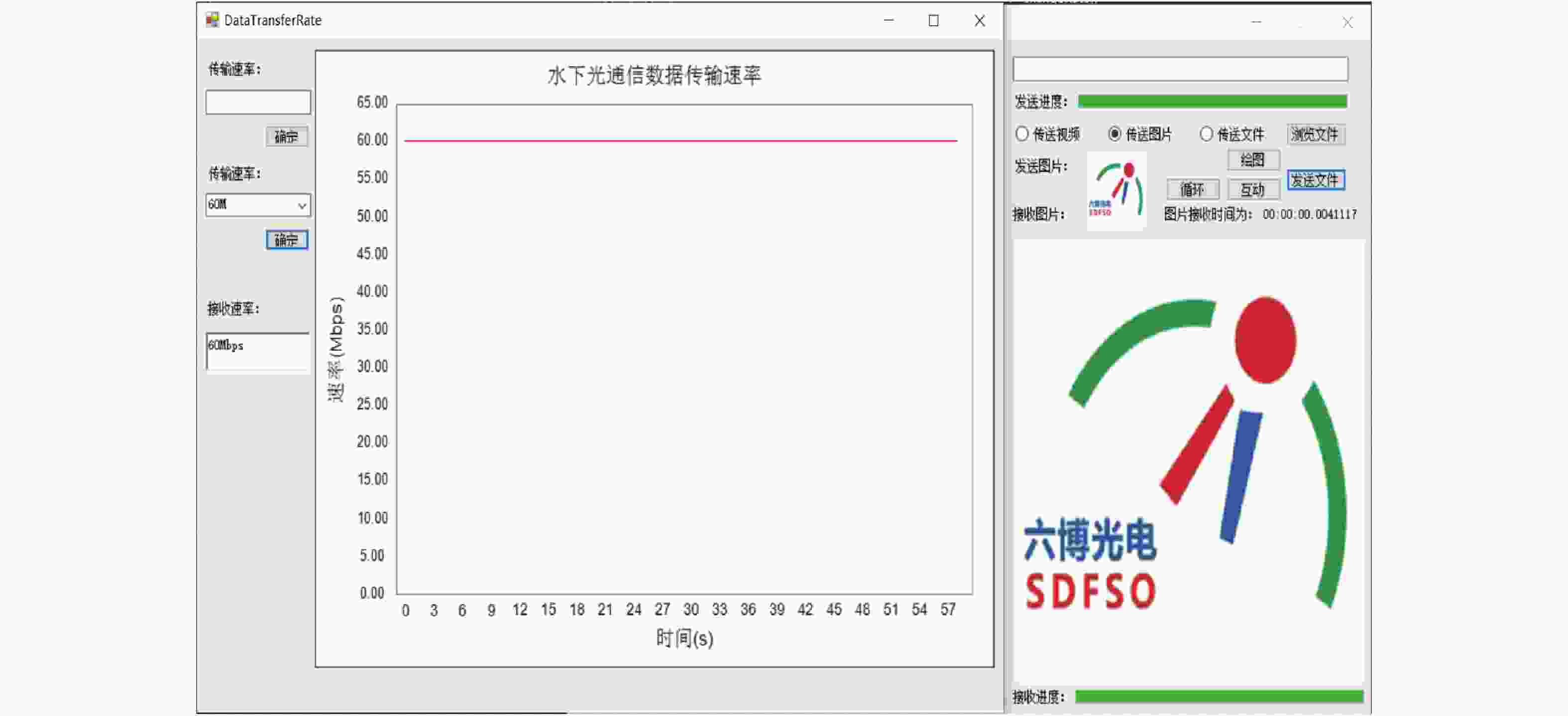
Figure 17. Upper computer display transceiver data diagram
-
文中设计了一种面向海洋商用的水下实时双向链路通信系统,完成了工程样机的设计及水下测试。进行了模拟水下实验测试结果显示,在通信距离1~60 m范围内系统实现了可靠的双向信息交互;在通信距离5 m、误码率10−7时,通信速率可达60 Mbps;在通信距离60 m、误码率10−7时,通信速率达10 Mbps。该工程样机初步验证了基于可将光的水下高速双向链路通信的可行性,下一步系统将进一步优化发射端调制技术,提高接收端探测灵敏度,提高通信距离。
Research and design of underwater wireless optical communication system with dual light sources
doi: 10.3788/IRLA20200445
- Received Date: 2020-11-21
- Rev Recd Date: 2020-12-16
- Publish Date: 2021-09-23
-
Key words:
- underwater optical communication /
- LD /
- LED /
- bidirectional link communication
Abstract: With the deepening exploration of ocean, underwater wireless communication technology has become the key to restrict its development. Aiming at the requirement of high speed and long distance underwater wireless communication, an underwater bidirectional link communication system for marine commercial was designed. The laser LD and LED dual emission light sources were adopted at the transmitting end, the system design scheme of dual emission light sources was proposed, and the feasibility of the scheme by designing the corresponding drive circuits was verified. At the receiving end, 5 mm large-area APD and high-sensitivity PMT dual receiving detector were used to receive optical signals, which were suitable for long-distance and high-speed communication. The information processing part of the system was completed by FPGA, and information interaction was carried out with PC through network communication. Finally, the whole system was designed and commercialized. The underwater simulation experiment shows that the communication rate of the system can reach 60 Mbps when the communication distance is 5 m and the bit error rate is 10−7. The communication rate of the system can reach 10 Mbps when the communication distance is 60 m and the bit error rate is 10−7.


 DownLoad: