


-
视觉测量以其高精度、非接触、自动化以及低成本等优势,被广泛运用在航空航天、汽车制造、建筑工程等领域[1]。作为以图像为信息载体的视觉测量方法,图像上目标定位的准确性直接影响着视觉测量的精度。除了镜头的畸变误差[2]之外,温度也会对成像系统测量精度造成影响:一方面透镜内光学材料的折射率会随温度变化,引起焦距和光轴的变化[3];另一方面温度的升高还会引起相机内部机械部件的热变形,导致图像膨胀变化,从而导致视觉测量系统误差[4]。高精度视觉测量系统的测量精度可以达到0.02 pixel,由温度变化引起的误差通常是不可忽视的,因此有必要研究温度变化对成像系统的影响以及消除热致图像坐标漂移的方法。
减小热致图像漂移最直接的方法是控制成像系统的温度恒定。陶力[5]研究热真空环境对视觉测量系统的影响,利用半导体制冷器和激光冷水机构建温控系统对相机进行局部温控,来减小温度对测量结果的影响。王领华等人[6]研究可见光航空相机的恒温设计,提出采用电加热膜、轴流风扇等主动热控方式和热控涂层、隔热垫等被动温控方式。王阳等人[7]研究透射式低温光学红外相机冷链热设计,通过低温热管传输和辐射制冷的方式为低温光学系统的降温。但是温控系统普遍存在结构复杂、庞大笨重、成本高等缺点。于是,研究热致像点坐标漂移的数学模型,并从软件上对其进行补偿,成为一种更为经济、可行的方法。20世纪90年代,相机温度变化对图像坐标的影响引起了人们的注意,Robson等人[8]发现数字相机在开机3 h后采集到的图像坐标发生最大约4 pixel的漂移。为解释像点坐标漂移的原因,Handel[9]提出由相机内部机械部件的热膨胀模型来解释其起源,但该模型只考虑相机的平移,认为相机的固有参数和姿态保持不变。事实上温度的变化会导致相机所有部件热膨胀,因此它的准确性和应用范围受到了限制。为了解决这一局限性,Yu等人[10]建立了图像坐标漂移与相机参数变化关系,并通过系统辨识方式建立相机参数与温度变化的关系模型。研究发现相机开机后集成电路板产生热量,热量传递到相机的部件,导致相机整体产生热变形,热变形引起相机参数产生变化,进而影响测量精度,这种效应称为相机自热效应。Smith和Cope[11]将相机放在冰箱中降低其内部温度来研究温度对相机参数影响,得出温度变化1 ℃,镜头焦距变化1 μm的结论。Podbreznik和Potocnik[12]以低成本相机为研究对象,建立温度变化对焦距、主点和畸变参数的影响模型,得出随着被测物与摄像机之间距离的增加,温度影响逐渐减小的结论。M. Daakir等人[13]发现相机热变形对相机内部参数(焦距、主点)的影响,并认为传感器温度变化是产生该影响的主要原因。LipingYu 和 Gilles Lubineau[14] 基于简化的立体视觉模型,仿真分析摄像机自热对三维坐标、位移和应变测量的影响,得出相机温度变化对立体数字图像相关技术的影响。Pan等[15]在针孔模型上研究温度变化对立体测量的影响,发现应变测量误差约为30~50 με/℃。在相机热致变形研究上,多采用实验的方式研究温度与图像整体膨胀变化的关系。Ma等人[16]通过对相机传热过程进行分析,发现相机达到热平衡时温度升高约10 ℃,相机镜头与传感器平面产生不同的平移量,得出相机组件温度与图像膨胀的关系。Zhou等[17]系统地研究了数码相机工作时的传热过程和温度特性,建立了相机热平衡时间和热平衡温度的模型。Pan等人[18]通过研究温度变化对立体测量的影响,提出将相机预热达到热平衡后再进行视觉测量的方法。目前研究工作主要集中在相机传热过程与相机成像参数变化和温度变化的关系。关于像点漂移研究集中在漂移的现象,并未充分分析漂移产生的根本原因,而且尚未有漂移大小、方向与温度变化关系的合理解释。
文中对相机自热引起的像点坐标漂移进行系统研究,提出一种针对工业相机热致像点漂移的补偿方法。首先,利用有限元技术对相机进行热应力分析,得出相机自热引起成像光路变化和传感器膨胀是造成像点漂移的主要原因。其次,分析相机热响应引起相机光路变化与成像器件径向膨胀对像点坐标的影响,建立图像像点漂移补偿模型。然后,通过实验数据论证像点漂移补偿模型。最后,通过与硬件热控装置抑制效果对比实验,验证了文中像点漂移补偿模型的有效性。
-
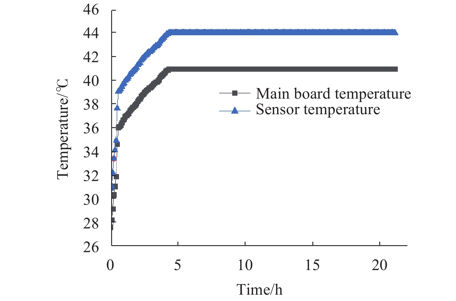
工业相机系统由相机壳体、集成电路板(相机运行热源)、支架和镜头组成。集成电路板主要是传感器和主板,当相机运行时,电路板产生的热量在相机部件和环境之间传递导致相机部件温度升高。图1为AVT GT5120工业相机和Nikon 35 mm定焦镜头组成的成像系统主板和传感器在开机之后的温度曲线,温度由相机内置温度传感器测量。在相机通电5 h后,图像传感器升温19 ℃、主板升温16 ℃后趋于稳定。在室温条件下,随着相机成像元件和主板温度的升高,相机内部呈现非均匀温度场,这种非均匀温度场是由相机内部热源与外界环境相互作用产生的结果,主要作用方式是热传导和热对流[19]。通过SolidWorks建立相机三维模型(如图2所示),根据相机器件的升温曲线添加温度载荷,应用有限元分析技术进行该温度场下相机的热应力求解[20-21]。

Figure 1. Temperature change of the imaging device and the main board after turning on
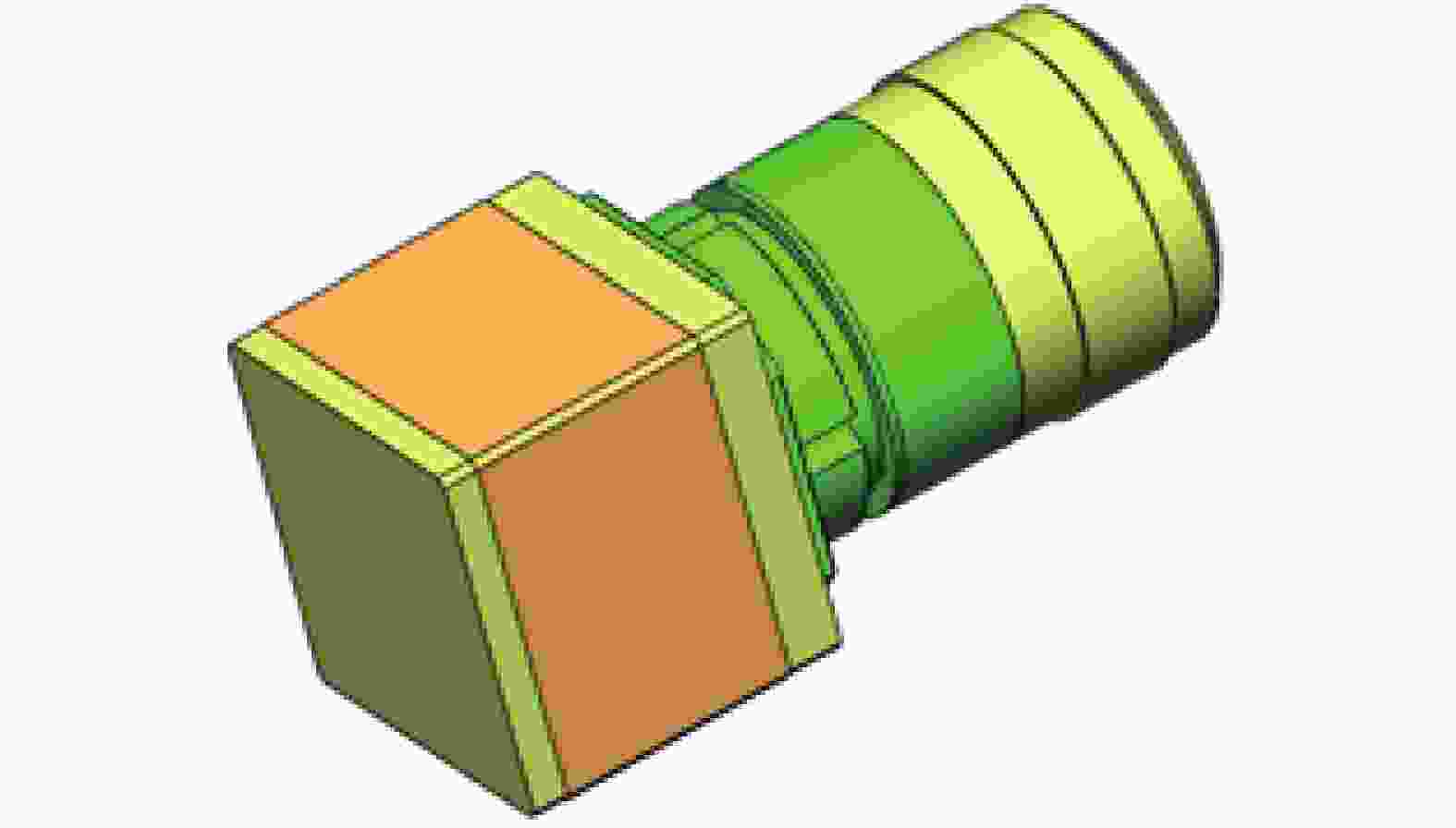
Figure 2. 3D model of AVT GT5120 camera
-
文中以AVT GT5120为研究对象,阐述工业相机热致图像坐标漂移模型与补偿方法。首先,为减小计算量并提高计算效率,将相机三维模型中影响较小的几何特征去除,如倒角、圆角和非安装孔。其次,检查模型干涉情况,保证相机模型各零件配合准确。然后,将装配体导入AnsysWorkbench,采用非连续六面体方法对相机三维模型进行网格划分,如图3(a)所示,并添加材料库(材料参数如表1所示)。

Figure 3. Camera finite element model
Name Material Young’s
modulus /GPaDensity
/kg·m−3Specific heat
capacity/J·kg−1·℃Thermal conductivity
W·m−1·℃Thermal expansion
coefficient/℃−1Poisson ratio Body Aluminum alloy 71 2770 875 237 2.3×10⁻⁵ 0.33 Lens tube, top plate Copper alloy 110 8300 385 401 1.8×10⁻⁵ 0.34 CMOS Monocrystalline Silicon 190 2330 702 124 5.0×10⁻⁷ 0.064 Lens housing ABS 2 880 1470 0.22 9.0×10⁻⁵ 0.394 Lens Glass 88 2500 750 1.4 5.8×10⁻⁷ 0.215 Table 1. Material properties of camera components
最后,以相机内置温度采集模块所得温度作为热载荷,将热载荷温度梯度添加在成像器件和主板位置,如图3(b)所示。设置热分析总时间22 h,时间增量300 s,相机外表面与空气对流系数
$5{\rm e}- 06\;(\rm W/{{\rm{mm}}}^{2}\cdot$ ℃),对相机进行瞬态热分析,得出相机整体温度场与热流场。将瞬态热分析结果导入瞬态热应力分析,设置相机底面为固定约束,与热分析设置相同的时间步,建立瞬态热应力耦合场。 -
采用间接耦合法对相机进行瞬态热力学分析,通过对相机模型设置相应的温度载荷和对流系数得出相机温度场和热流场,将温度梯度导入瞬态应力场并设置固定约束得出相机变形场。相机在常温20 ℃下工作时,自热达到热平衡状态后,最高温度为35.60 ℃,最低温度为22.75 ℃,温差为12.85 ℃,相机内部呈现非均匀温度场,温度从机身到镜头逐渐降低,温度场分布如图4(a)所示。集成电路板在机身内部,导致机身温度变化幅度最大;镜头接口与机身直接连接且材质为金属,因此热量很容易传到此处引起接口的温升;相机镜头采用机械连接且材质热传导系数小,加上与外界进行热交换,所以温升较小。自热导致相机内部的热流场如图4(b)所示,热量从热源处向镜头和相机四周传递,导致相机各部件产生变形,相机各部件在光路方向产生的变形在镜头处产生累加,导致镜头处的变形量最大,相机整体变形场如图4(c)所示。表2列出了不同温度变化量下,镜头位移、CMOS变形量的仿真数据。可见,随着温度升高,镜头与CMOS在光轴方向上的偏移量逐渐增大,且镜头偏移量大于CMOS偏移量,同时温度变化与变形量变化存在线性关系。CMOS在成像面内的变形量随温度升高逐渐增大,并存在线性关系。CMOS变形场如图4(d)所示,由图中可以看出,CMOS变形包括沿镜头方向的轴向位移以及面内的径向变形。文中通过分析相机组件热变形得出像点漂移的变化规律,进而建立相机像点漂移补偿模型[22]。

Figure 4. Camera transient thermal stress analysis results
Temperature
increasement/℃Lens
translation/μmCMOS horizontal
deformation/μmCMOS vertical
deformation/μm0 0.00 0.00 0.00 1 4.28 2.61 2.31 2 9.61 5.25 5.28 3 14.44 7.52 8.02 4 19.76 9.75 10.04 5 24.19 12.61 13.02 6 28.89 15.32 14.89 7 32.58 18.32 17.65 Table 2. Deformation of the lens and CMOS under different temperature variation
-
通过有限元技术分析自热引起的相机变形情况,得出导致像点漂移的两个因素。相机组成器件变形使成像光路发生轴向变化,在物理上表现为成像模型中物距和像距的变化,从而导致成像点向外漂移;CMOS与顶板的热膨胀变形使原始成像范围减小,进而产生像点向内(主点中心)漂移。
-
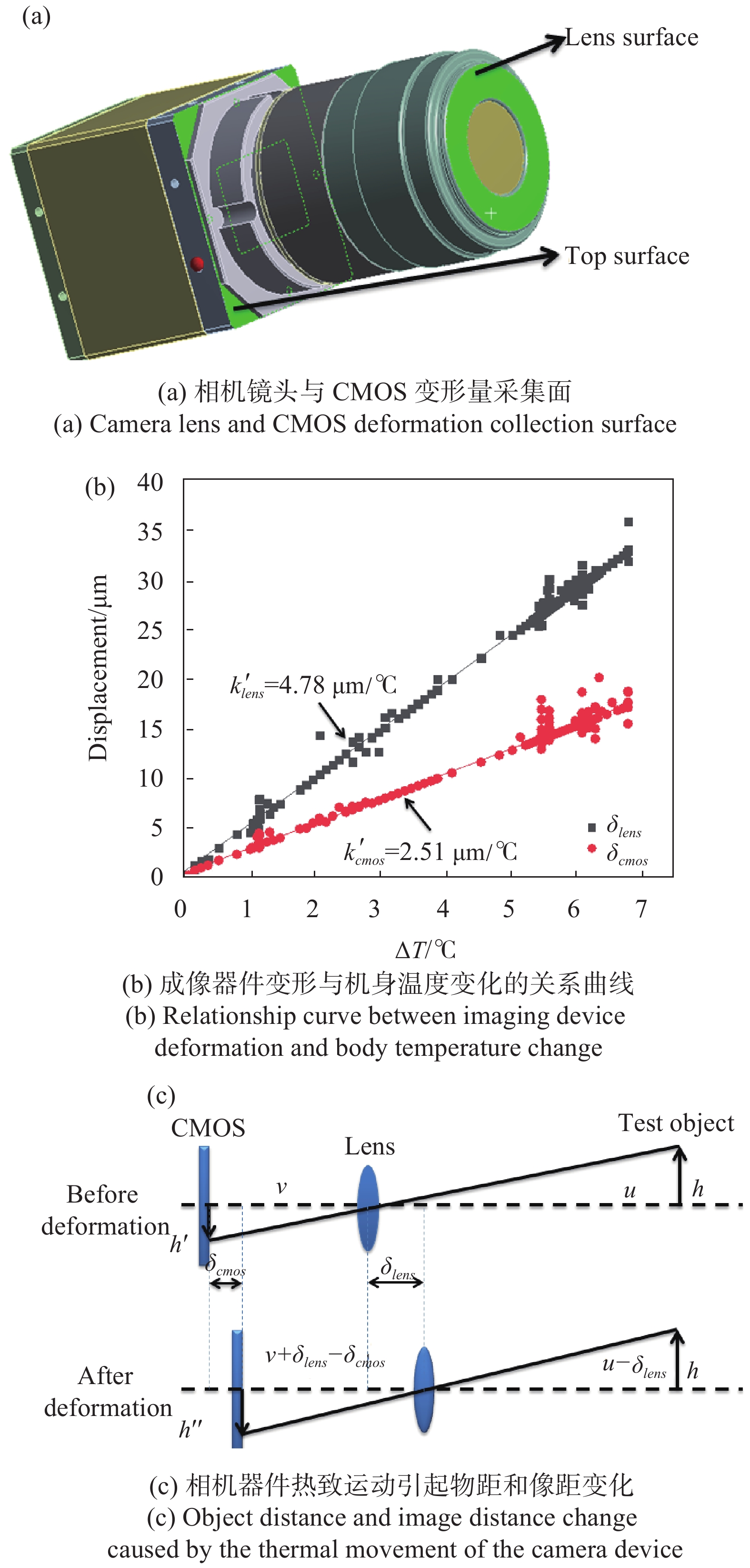
如图5(a)所示,在小孔成像基础上,以相机镜头面和顶板为偏移量采集面分析相机热致变形引起的成像光路变化。通过有限元计算可以得出镜头面和顶板的偏移量,偏移量与机身温度变化关系如图5(b)所示,可以看出,镜头的偏移量
${\delta _{lens}}$ 大于CMOS的偏移量${\delta _{cmos}}$ ,这是由于镜头位于相机传热的最末端,镜头在光轴方向的偏移量${\delta _{lens}}$ 为CMOS偏移、支架偏移和镜头偏移合成量,CMOS偏移量${\delta _{cmos}}$ 为顶板与CMOS偏移合成量。镜头与CMOS偏移量与相机温度变化存在较好的线性关系,对偏移量与机身温度变化量进行线性拟合,计算得出热变形参数为$k_{lens}^{'}$ 和$k_{cmos}^{'}$ :
Figure 5. Axial offset of the camera causes the imaging optical path to change
式中:
$\Delta T$ 为机身温度变化量。相机轴向偏移量就是相机成像平面和等效光心的移动,从而引起像距$v$ 及物距$u$ 的变化,如图5(c)所示。可见,相机自热引起镜头和CMOS同时向前移动,从而导致物距
$u$ 减小到$u - {\delta _{lens}}$ ,像距$v$ 增加到$v + {\delta _{lens}} - {\delta _{cmos}}$ 。在针孔模型上分析像点变化关系:式中:
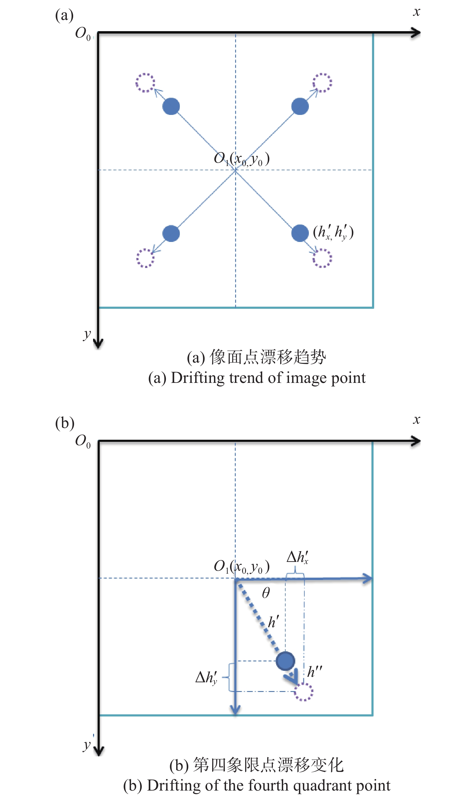
$({x_0},{y_0})$ 为主点坐标;$(h_x^{'},h_y^{'})$ 为像点初始坐标,$u$ 为物距;$v$ 为像距;${\delta _{lens}}$ 为镜头的偏移量;${\delta _{cmos}}$ 为CMOS的偏移量;${h^{'}}$ 为初始像点与主点之间的距离,${h^{''}}$ 为像点漂移后与主点之间的距离。如图6(a)所示,像点以主点为中心向四周漂移,每个象限的漂移方向不同,主点位置处的像点坐标不发生变化。
Figure 6. Image point drift caused by axial optical path changes
以第四象限点为例研究像点漂移情况,如图6(b)所示,像点漂移量
$\Delta {h^{'}}$ 为:联立公式(3)~(5)可得成像光路变化产生的像点漂移量:
像点与主点连线的夹角
$\theta $ 为:将像点偏移量
$\Delta {h^{'}}$ 在水平和竖直方向上分解,即:$\Delta h_x^{'}$ 为水平方向像点漂移量,$\Delta h_y^{'}$ 为竖直方向像点漂移量。 -
CMOS受热膨胀导致像点发生径向漂移,CMOS(材质为单晶硅)的热膨胀系数远小于相机机身顶板(材质为铜合金)的热膨胀系数,但由于CMOS与相机顶板固定在一起,顶板热膨胀带动CMOS发生围绕传感器中心的径向变形。CMOS径向膨胀引起的坐标漂移与轴向光路变化产生的漂移具有相反的趋势,成像器件的热膨胀导致成像面扩张,进而造成像点向图像中心漂移,如图7(a)所示。

Figure 7. Schematic diagram of image point shift caused by radial expansion
在不同象限的成像点具有不同的漂移方向,以第四象限为例分析成像器件膨胀导致的像点漂移,如图7(b)所示。根据铜合金底板的膨胀系数
${k}_{cmos}= $ $ 1.8\;\rm e-05/^\circ {\rm{C}}$ 计算像点漂移量为:进一步将成像器件膨胀引起的像点漂移量在水平方向和竖直方向上分解:
联合公式(1)、(2)、(8)、(9)、(11)、(12)可以得出温度变化引起像点在水平和竖直方向的漂移量为:
其他象限像点坐标漂移也可以通过相同的方式分析获得。
-
拍摄对象为带回光反射标记点的陶瓷板,如图8(a)所示固定在光学平台上。拍摄相机为AVT Prosilica GT5120红外相机,分辨率为
$5\;120 \times 5\;120$ pixel,像元尺寸为4.5 μm×4.5 μm,搭配尼克尔AF 35 mm定焦镜头,如图8(b)所示固定在光学平台上。使用红外光源照明陶瓷板,令回光反射标记点成像更清晰。相机与陶瓷板相距1.5 m,并且使相机光轴近似垂直于陶瓷平面。相机内部有两个温度传感器,可以检测相机主板和CMOS温度,测量精度为0.1 ℃。同时,在相机机身、陶瓷板处额外放置测温仪,测量并记录相机和陶瓷板的温度变化,测量精度为0.1 ℃。设计图像采集软件控制相机每5 min采集一次图像,通过灰度重心法求取回光反射标记点的图像坐标,并实时保存图像坐标和采集时刻的温度。
Figure 8. Temperature changes of the experimental device and its components
相机主板、CMOS传感器、机身与标定板温度变化如图8(c)所示,CMOS与主板的温度在开机5 h后达到平衡,机身温度变化因热传导过程缓慢而存在延时性。为减小环境温度与光照变化对实验的影响,实验中使用幕布将实验环境封闭,实验环境及标定板的温度变化只有±0.2 ℃。根据陶瓷材料热膨胀系数得出其最大热膨胀量为0.2 μm,引起的像点漂移量为0.001 pixel,对实验结果造成的影响可以忽略不计。
考虑靠近图像边缘成像点漂移效果明显,图像中心像素坐标为(2560, 2560),选取图像边缘的成像点对模型准确性进行分析。根据公式(13)~(14)计算得出相机自热引起的像点漂移量,对初始像点坐标漂移量进行补偿,将补偿后像点的坐标同实测坐标进行比较评价模型的准确性,结果如图9所示。
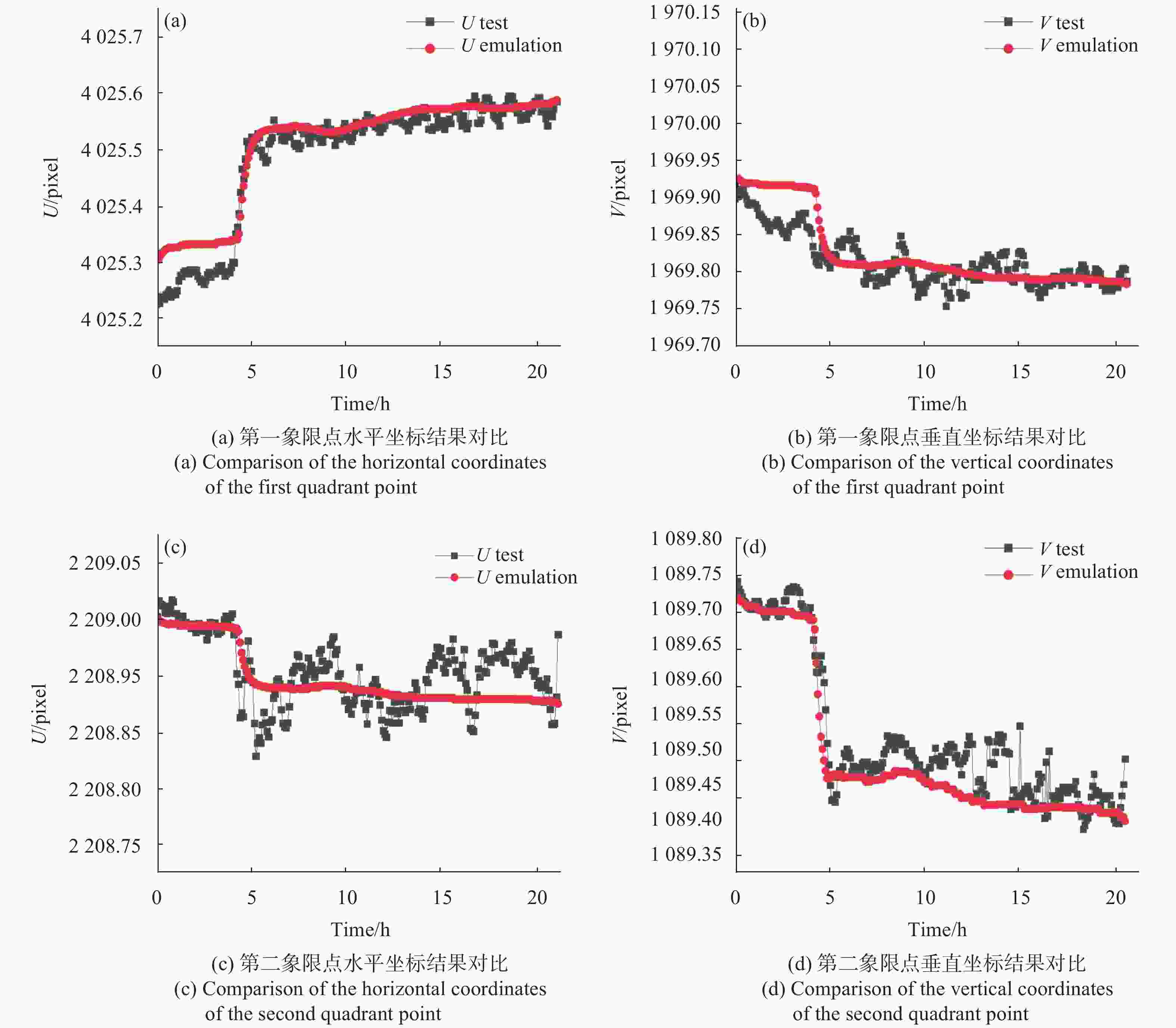
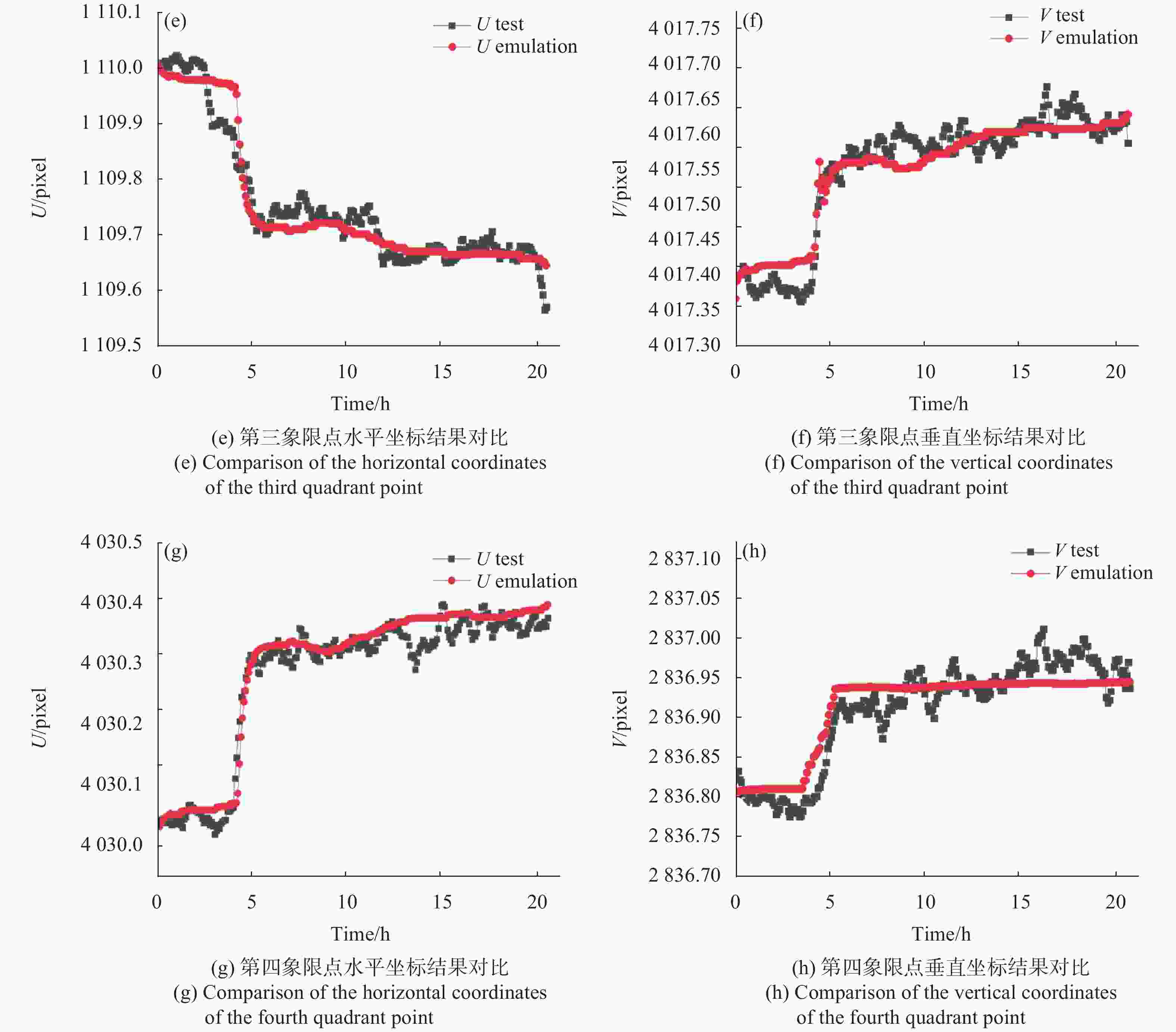
Figure 9. In the self-heating state, the coordinate value of each quadrant point after compensation is compared with the experimental measurement value
通过对比实验可以看出,经过该模型补偿后的像点坐标同其实测坐标有很强的相关性,进而验证了像点漂移补偿模型的有效性。同时,从实验测量结果可以看出,以开机时刻像点坐标为基准,相机自热导致像点产生
$0.4 \sim 0.6$ pixel漂移量。以升温后目标点坐标实测结果为真值,将像点漂移模型仿真结果与实验测量结果作差处理,可以得出像点漂移补偿模型误差,误差绝对值统计结果如表3所示。First quadrant error/pixel Second quadrant error/pixel Third quadrant error/pixel Fourth quadrant error/pixel Minimum Max Minimum Max Minimum Max Minimum Max Horizontal coordinate value 0.00 0.09 0.00 0.12 0.00 0.12 0.00 0.13 Vertical coordinate value 0.00 0.10 0.00 0.20 0.00 0.15 0.00 0.16 Table 3. Pixel drift compensation model error
可以看出,通过温度补偿模型进行补偿后,可以将温度升高导致的像点漂移从
$0.4 \sim 0.6$ pixel降低到$0.1 \sim 0.2$ pixel,验证了文中提出的像点漂移补偿模型的有效性。 -
工程上通过对相机进行隔热设计减少相机温度变化对成像系统的影响[22]。文中设计制作了一套温控系统,如图10(a)所示,温控系统使用隔热材料隔绝相机与外界之间的热传导,同时使用固定在上层的导热片将多余热量导出,实验证明相机自热状态下,温控装置将相机主板和传感器温度控制在±0.1 ℃,有效抑制相机自热温度变化对成像系统的影响。
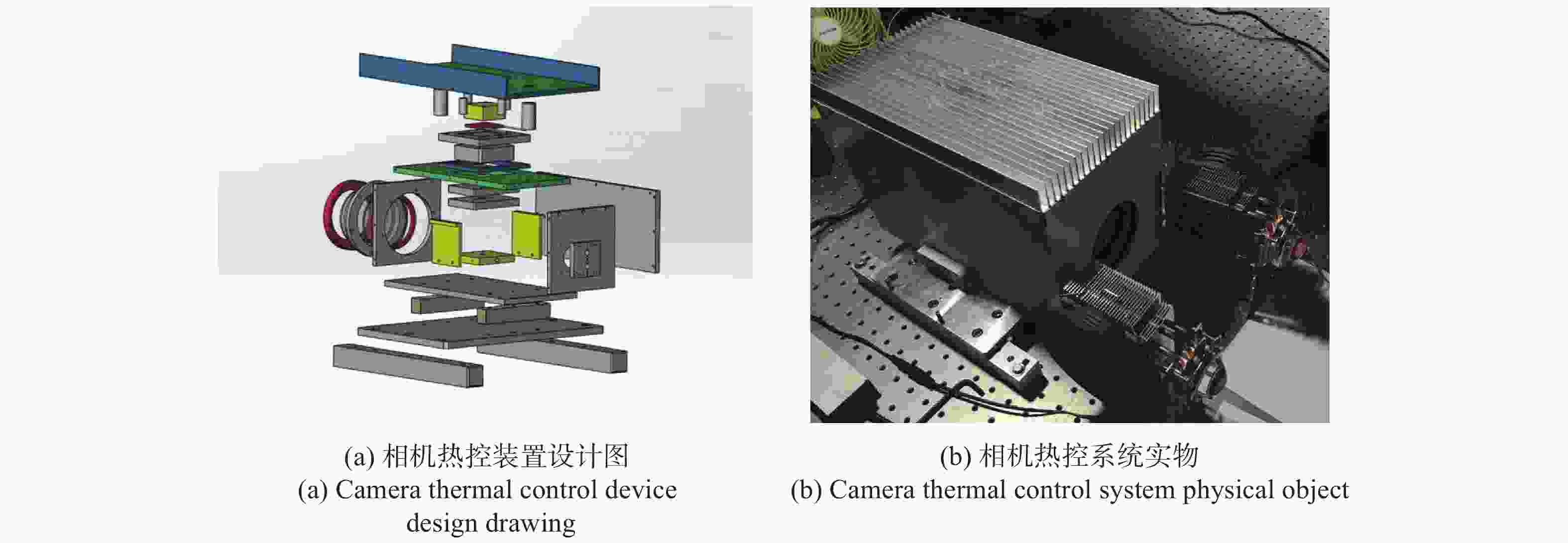
Figure 10. Camera thermal control system
在相似实验条件下,将相机放在温控系统内部,如图10(b)所示,同样记录相机开机后目标点图像坐标变化。对比热控设计方案与温度补偿模型对于像点漂移的抑制或补偿效果,四个象限像点漂移误差绝对值的统计结果如表4所示。
First quadrant
error/pixelSecond quadrant
error/pixelThird quadrant
error/pixelFourth quadrant
error/pixelMinimum Max Minimum Max Minimum Max Minimum Max Thermal control device method 0.00 0.20 0.01 0.17 0.02 0.13 0.01 0.15 Image point drift compensation method 0.00 0.10 0.00 0.20 0.01 0.15 0.00 0.16 Table 4. Comparison of thermal control device method and image point drift compensation method
可以看出,两种方案对像点漂移抑制效果非常接近,也进一步证明温度补偿模型的正确性。考虑到热控装置结构复杂、质量大、成本高的缺点,文中提出的温度补偿模型具有明显的优越性。
-
文中对工业相机自热引起的像点漂移进行了系统研究:通过对成像系统进行有限元热分析,得出工业相机自热引起相机成像光路变化和传感器径向膨胀;进一步在针孔模型基础上,建立像点漂移与温度变化之间的关系,提出图像像点漂移补偿模型。实验结果表明,文中提出的像点漂移补偿模型使相机自热引起的像点误差从0.4~0.6 pixel降低到0.1~0.2 pixel,取得与硬件温控系统相同的效果。像点漂移补偿模型可以对相机自热引起的坐标误差进行有效补偿,降低温度对图像测量的影响,对提高以图像为载体的测量方法的测量精度具有重要意义。
Model and compensation method of image point drift caused by self-heating of industrial camera
doi: 10.3788/IRLA20200494
- Received Date: 2020-12-15
- Rev Recd Date: 2021-03-21
- Publish Date: 2021-06-30
-
Key words:
- vision measurement /
- image point drift compensation model /
- finite element /
- industrial camera self-heating
Abstract: In order to reduce the influence of temperature on the image point coordinates of industrial cameras in visual measurement, the image point drift caused by the self-heating of the camera was studied, and a compensation method for the thermal image point drift of industrial cameras was proposed. The finite element simulation analysis of the industrial camera model through Ansys Workbench shows that the self-heating of the industrial camera will cause the imaging optical path change and sensor expansion change, quantitatively the influence of the optical path change and sensor expansion on the image point coordinates was analyzed, and the image point drift compensation model was established. A large number of experiments have shown that the image point drift error compensated by the model is reduced from 0.4-0.6 pixel to 0.1-0.2 pixel, which is equivalent to the image point drift suppression effect achieved by hardware thermal control. However, compared with the thermal control device, the method of using the model for compensation has obvious advantages of simple structure and low cost. The temperature compensation model proposed in this research provides a theoretical basis for reducing the image point drift error caused by the self-heating of the camera in the visual measurement.


 DownLoad: