


-
红外导引头工作环境极其恶劣,其制导精度容易随温度环境、随机振动而发生漂移;为提高对复杂场景目标的识别能力,双色制导乃至多色制导是红外导引头的发展趋势,然而双色/多色红外导引头制造、装调过程中对准精度要求极高而现有制造、装调手段较难满足要求。恶劣工作条件或多色制导体制对弹载红外探测系统带来的一个最主要误差是离焦。由于离焦主要是由红外光学系统带来的,因此,增大红外光学系统的焦深是解决以上问题最直接的途径。但光学系统的焦深由其F/#和工作波段决定,对弹载红外光学系统而言,其焦深是一个固定且较小的值。
相比传统成像探测体制中只有光学成像这一步,波前编码是结合光学成像和数字图像处理两步成像的计算成像技术。其通过在系统光瞳位置加入特殊的相位掩模板,对目标信号光波进行编码调制,并在图像处理端对该编码信号进行解码而恢复原图像。由于被编码调制后的波前对离焦等像差的不敏感度扩大了十数倍,因此,波前编码技术能显著扩大光学系统焦深[1-2]。此外,相比传统探测系统只捕获到目标的强度信息,波前编码系统还捕获到目标的相位、光谱、偏振等信息,对目标的识别能力会进一步增强[3]。
综上,波前编码技术在编码与解码之间实现抑制光学导引头温度偏差、力学环境影响以及降低多色导引头的对准难度。文中基于波前编码技术扩大焦深的原理研制了成像样机,对成像样机采集、处理的图像进行了分析,验证了波前编码技术在扩大焦深方面的能力,同时基于弹载应用平台,分析了目前波前编码技术应用上存在的一些问题。
-
普通光学系统中,目标景物经光学系统成像于光学系统像面处,根据傅里叶光学理论,不考虑噪声的情况下,成像的物理过程可描述为目标景物与光学系统点扩散函数的卷积,空间频域为目标景物与光学传递函数的乘积。
式中:
$G(u,v)$ 为已知观测图像的频域;$H(u,v)$ 为光学系统点扩散函数PSF的频域,即光学系统的OTF(当系统存在像差时,OTF为退化函数);$F(u,v)$ 为目标景物的频域;u,v为像素强度对应的空间频率。如图1所示,波前编码系统中,通过在普通光学系统的光瞳面上加入一个相位掩模板对波前进行编码,使光学系统PSF和OTF对系统存在的像差不敏感,在探测器上成一系列模糊的编码图像,再对编码图像以图像复原的方式进行解码,得到清晰图像。

Figure 1. Principle of wavefront coding
其成像过程的物理模型为:
式中:
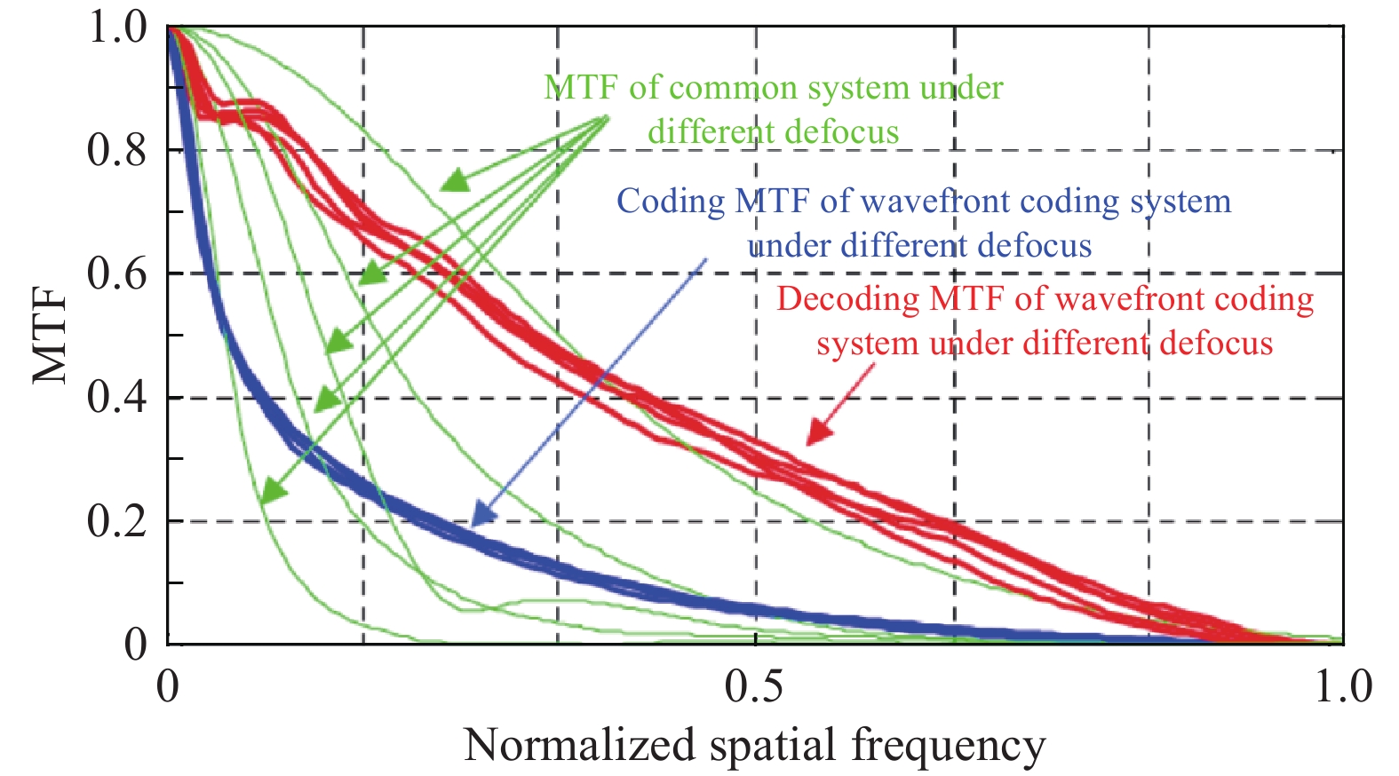
${G_{\rm{encode}}}(u,v)$ 为光学系统像面上获得的编码图像的频域;${H_{\rm{encode}}}(u,v)$ 为光学系统编码过程的OTF;${G_{\rm{decode}}}(u,v)$ 为解码图像的频域,即为最终图像;${H_{\rm{decode}}}$ 为光学系统解码过程的OTF。一般情况下,解码过程就是在已知系统编码过程OTF情况下完成图像复原过程。由于OTF为复数,计算时一般采用其模量MTF。波前编码系统为两步成像,系统的MTF由编码和解码过程的MTF组成。图2为波前编码系统MTF与普通系统的差别。普通系统MTF随离焦变化明显,幅度迅速下降,离焦值较大时,空间频率出现截止现象,说明其成像质量对离焦像差较为敏感。波前编码系统中,编码MTF随离焦几乎无变化,说明编码图像质量对离焦不敏感。尽管编码MTF值相对衍射受限系统有所下降,但空间频率无截止,由于编码MTF各离焦位置较为稳定,可通过同一解码OTF实现不同离焦位置图像的解码,解码后全系统的MTF接近于衍射限。

Figure 2. MTF of common system and wavefront coding system
-
所谓像差钝化设计是指通过设计特定的相位掩模板使得波前编码系统成像特性在所需的景深或动态像差范围内不变。Fisher信息理论优化方法是相位掩膜板参数优化的常用方法[4-5]。使用OTF构造的Fisher评价函数可表示为:
式中:H为规格化的OTF;K为噪声与场景功率谱之比;σ为最小可接受的噪声放大。
考虑掩模板制造和装调,掩模板相位采用三次多项式表征:
式中:a为多项式参数。
光学系统F/#为1.4,工作波长为6.5~8.5 μm(IR1)和9~10.5 μm(IR2),则其最小焦深为Δ≈±2λ(F/#)2=±25 μm。焦深若扩大10×,即为±250 μm,将使得弹载光学系统完全满足力热环境和几乎不考虑双色对准精度。在10倍焦深位置分别提取系统各视场PSF,建立相位掩模板参数优化函数实现相位掩膜板参数优化,得到a=5.12×10⁻⁶,将其代入光学设计软件,得到如图3所示的光路。图4给出了在±250 μm离焦范围内波前编码光路在两个波段内的离焦特性,可以看出:波前编码系统在离焦范围内MTF调制度变化不大,说明其具备较高的离焦像差抑制能力。

Figure 3. Optical path of double bands wavefront coding
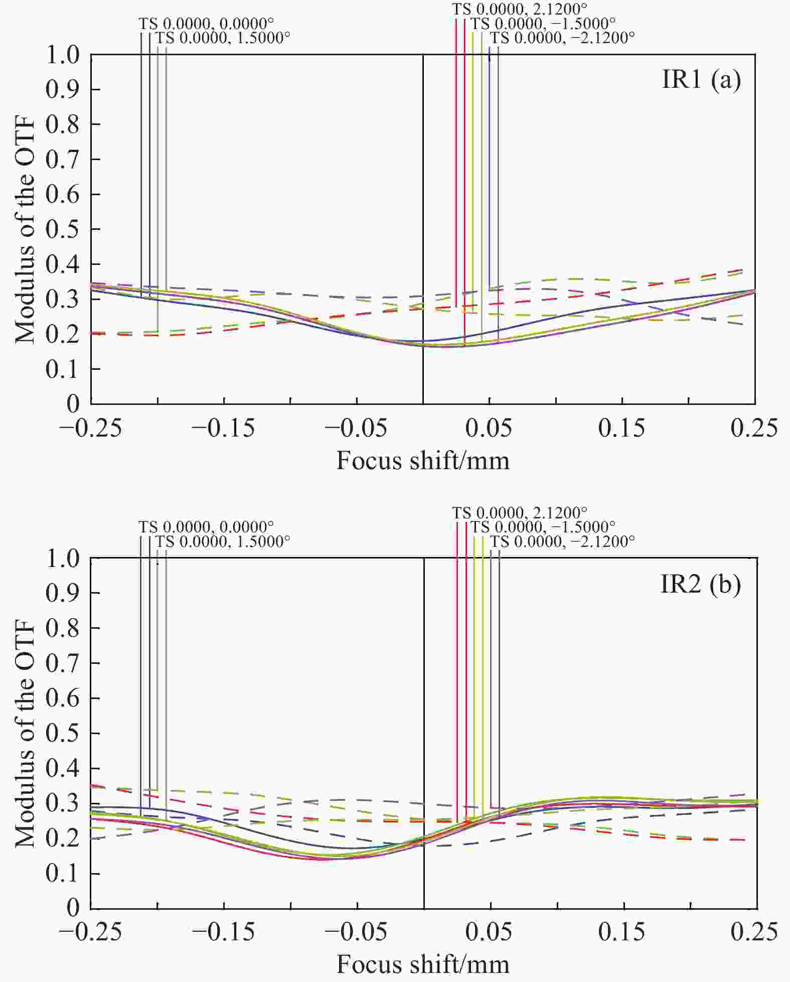
Figure 4. Defocus characteristics of double bands wavefront coding (at 10 lp/mm)
-
图3所示波前编码系统在长焦大口径平行光管系统中进行成像实验,目标是被准直的红外靶标,红外目标包括点靶、十字靶和四条靶,在一定的目标与背景温差下记录编码图像,并将编码图像解码为原图像。由于验证波前编码技术的可行性只需一个波段的显示,因此,下文将以IR1波段采集的图像作为说明。
取小孔点靶采集的点目标图像作为实测PSF,该PSF值被使用来解码十字靶和四条靶图像。图5为目标与背景温差为5 ℃时波前编码系统记录的编码PSF,为了便于观察,将图像灰度进行了拉伸处理。图中圆形区域内可以辨别出三角形图案,即为点靶标成的像,也就是系统PSF。将该位置的图像提出来,经过处理即可获得所需的PSF,用于去卷积复原。

Figure 5. PSF of wavefront coding(IR1 brand)
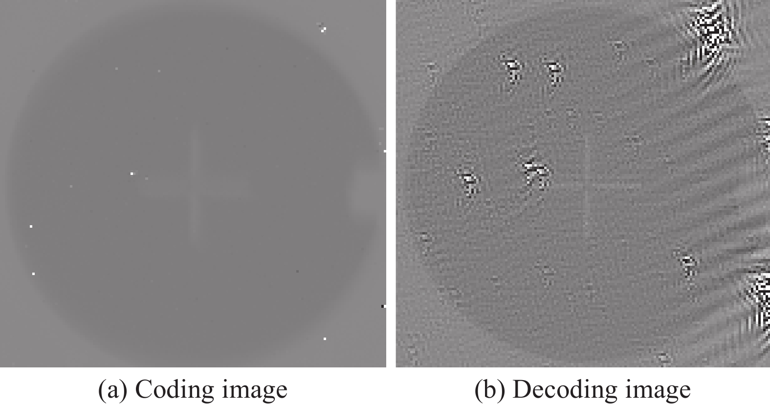
调整探测器与光学系统的相对位置,使得离焦量为300 μm,设置目标与背景温差为5 ℃,系统对十字靶和四条靶采集的图像如图6、7所示。从图6、7可以看出:解码图像清晰可辨,验证了波前编码技术对于系统像差或离焦像差的抑制能力。

Figure 6. Coding and decoding images of cross-bar at 300 μm defocus position (IR1 brand)
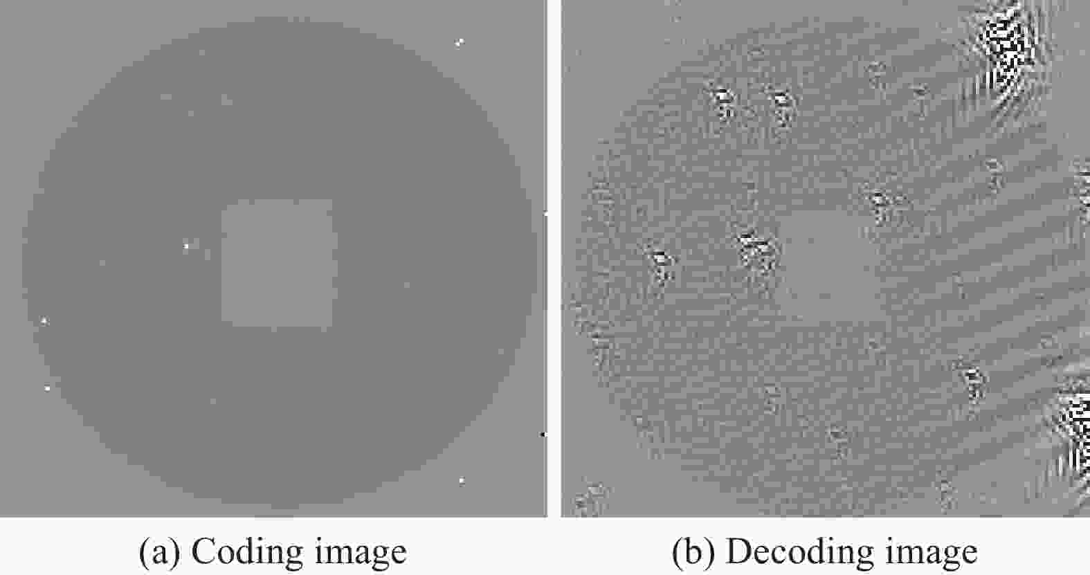
Figure 7. Coding and decoding images of four-bar at 300 μm defocus position (IR1 brand)
-
从图6、7中可以看出:解码图像在非目标位置出现条纹,而在目标位置并未出现条纹。这是由于仅使用目标位置的PSF复原整幅图像产生的。由设计结果中的不同视场的MTF可以发现,尽管MTF在不同的离焦位置趋于一致,但其在不同视场的情况下仍存在区别,其成像具有一定的空间变化特性。图8给出了点阵目标编码图像空间变化特性,从图中可见在不同的视场位置,其点目标图像存在差异。仅使用单一PSF复原编码图像时,将产生一定的伪像,这一伪像就是解码图像中的条纹。可在实际目标采集中,提取不同视场位置PSF,使用空间变化解码算法实现条纹消除。

Figure 8. Spatial variation characteristics of wavefront coding images
-
传统成像系统由于制造与装调误差,实际系统的传递函数相对衍射极限总是存在一定的下降,而波前编码技术可以通过解码使得系统传递函数接近衍射极限,因此波前编码技术对图像分辨率有一定的提高[6],然而分辨率并不是弹载系统考虑的重点,能量的增加或信噪比的增加才是弹载系统考虑的重点。此外,传统成像系统的噪声在固定场景下可认为是一个固定值,波前编码技术在解码图像时会对信号进行消弥散处理,即放大信号,但与此同时会对这个固定噪声进行放大,处理不当就容易导致信噪比降低。
在实际系统中由于采集的编码图像中含有各种不同来源的噪声,单纯的LR去卷积方法不能保证图像重构的较好结果,使得解码图像噪声较大,在实际应用中,需对图像噪声进行抑制,使用去噪算法来获得像质更佳的成像结果[7-8]。由于红外成像系统受外界环境影响较大,其解码图像一般噪声也将较大,这是波前编码技术在弹载红外系统应用过程中需要重点考虑的问题。
-
波前编码技术只需在传统光学系统的光瞳位置加入一片相位掩模板即可获得极大的焦深范围,这对工作在恶劣力热环境下的弹载红外成像系统而言是巨大利好。此外,为提高对复杂场景目标的识别能力,双色乃至多色共口径制导是红外导引头的发展趋势。由于目前双色共口径制导的焦点在集成探测器上,而集成探测器多芯片的对准又是一大制造、生产难题,采用波前编码技术增大焦深可以极大地缓解该难题。
基于弹载平台的应用,文中介绍了波前编码技术扩大焦深的原理,基于该原理进行了10倍焦深扩大的双色红外光学系统像差钝化设计,并集成样机进行了成像测试。测试结果表明:在10倍焦深位置的解码图像清晰可分辨,验证了波前编码技术对于系统像差或离焦像差抑制能力的可行性。最后,文中对波前编码的成像效果进行了分析:解码图像的水波纹是由于空间采样PSF不足导致的,可提取不同视场位置PSF,使用空间变化解码算法实现条纹消除;由于解码图像会在放大信号的同时放大噪声,因此解码算法需要进一步研究噪声抑制算法,以期满足弹载高能量、高信噪比应用的要求。
Double bands missile-borne infrared detection system of extended focus depth based on wavefront coding
doi: 10.3788/IRLA202049.0404001
- Received Date: 2019-12-20
- Rev Recd Date: 2020-01-11
- Available Online: 2020-01-09
- Publish Date: 2020-04-24
-
Key words:
- wavefront coding /
- focus depth /
- infrared detection /
- aberration inactivation
Abstract: In the technology of wavefront coding, a special phase mask is put at the position of optical system stop. Then the goal signal wavefront will be coded. At the image processing part, the coded signal will be decoded to the original image. Because the insensitivity of the coded wavefront to the defocus and other aberrations is ten times more, the focus depth will be extended ten times more. So the wavefront coding can solve the defocus and alignment error caused by terrible mechanics and heat environment using coding and decoding. Based on the extended focus depth principle of wavefront coding, an aberration inactivation long/long double bands infrared optical system was designed. The focus depth was extended to be 10 times more. Imaging test was carried out with the wavefront coding prototype. The coding image of the spot-bar was used as the PSF to decode the image at the 10 times defocus position of cross-bar and four-bar. After decoding, the image of cross-bar and four-bar was with high resolution. At the last, the imaging results of wavefront coding were analyzed. The ripple of decoding picture was caused by not enough spatial sampling. After sampling PSF of different field, the ripple could be eliminated by using decoding algorithm of spatial transformation. The signal and noise would be extended at same time while the image was decoding. So the noise suppression algorithm used in decoding should be further researched to satisfy the missile-borne demand of more energy and higher signal to noise ratio.


 DownLoad: