


-
近年来,随着世界航空工业的蓬勃发展,航空发动机的研制和发展均呈现出了逐渐加快的态势。在这种形势下,新一代航空发动机日益向着推力更大、质量更轻、寿命更长、推重比更高、耗油率更低、耐久性更好以及可靠性更优良的方向发展[1]。而要实现这样的目标,就需要进一步提高涡轮前的燃气温度。目前,推重比为10的航空发动机的涡轮前燃气温度约为1 940 K[2],已经超越了工作在此温度环境下的高压涡轮叶片材料的耐温极限。
因此,必须采取一定的技术手段来提高高压涡轮叶片的承温能力,以确保其能够长期、稳定地工作,其中的重要措施之一就是在叶身型面和缘板等部位上设计了大量的结构复杂、分布不均的冷却气膜孔(以下简称“气膜孔”),以实现对叶片的冷却和保护[3]。具体说来,分布于高压涡轮叶片上的气膜孔,数量通常为几十到几百个,而且孔径非常小,大多处于Φ0.3~Φ1.5 mm之间,而深径比则为1~3。研究表明:高压涡轮叶片在高温高压下的机械性能和冷却效果与气膜孔的孔径、分布位置和轴线角度等形位参数有着密切关系。因此,为了确保加工出的气膜孔符合高压涡轮叶片的设计要求,从而达到最佳的冷却效果,必须对气膜孔的实际几何技术状态实施监控。
通常说来,对于气膜孔的质量控制和要求主要体现在:(1)孔径,公差值一般为0.10 mm,而且要为通孔;(2)空间位置,主要包括几何位置和孔间距等,位置度公差一般为0.10~0.15 mm;(3)轴线角度,一般要求控制在±1°范围内。
为了解决气膜孔形位参数的测量难题,文中基于视觉测量与多轴联动原理,设计并搭建出了非接触式的四轴视觉坐标测量系统,以充分应对大量气膜孔的制造质量检测与评价任务。然而,要获取分布于叶片上且处于不同方位的全部气膜孔的实际测量数据,还需借助于回转运动轴(第四轴)的配合来实现高压涡轮叶片的转位,以实现四轴联动测量[4]。这就需要首先通过标定手段来确定回转轴线在测量空间中的方位,从而将不同视角下获得的测量数据转化到相同的坐标系中,以进行后续处理。徐永安、丁红等为了实现三维激光扫描仪的旋转扫描测量,将标定球固定于转台上,然后旋转并测量不同位置的标定球,以计算出不同位置的球心及其所在平面的法矢,再利用几何变换计算出球心所在圆的圆心,从而精确标定出了转台轴线的空间方位[5-6]。谭文斌、李想等针对θFXZ型测量机的回转轴线标定问题,提出了应用环形标准件的内孔和外圆进行回转轴线快速标定的方法,使标定后的该型测量机对其它型号环形标准件的测量误差处于±0.001 mm之内[7-8]。何万涛等针对所开发的四轴非接触测量设备的特点与航空叶片的测量需求,提出了一种带半径约束的最小二乘球心拟合方法,通过八个方位的球面扫描数据拟合出球心与法线方向,实现了转轴方位的精确标定[9]。虽然上述方法均涉及到了非接触式四轴测量系统中的回转轴线方位标定问题,但所针对的均为激光扫描测量系统,其测量原理与采用工业影像测头作为前端传感器的四轴视觉坐标测量系统不同,因而无法适用。然而,在文中设备条件下的回转台轴线的空间方位标定问题,是此类测量系统成败的关键所在,但目前尚未有有效且可靠的解决方法报道。
为了实现高压涡轮叶片上的气膜孔特征的高精高效测量,文中搭建了非接触式的四轴视觉坐标测量系统,并针对其中的回转轴线的空间位置标定难题,结合工业影像测头自身的特点,提出了一种基于视觉测量的回转轴线标定方法。在该方法的实现过程中,采用了定制的长方体标定块,并通过回转工作台与三坐标测量机之间的配合,使工业影像测头对焦于标定块的表面并采集其锋利棱边的图像,而后再通过边缘提取、像素距离计算、物理距离转化和代数运算等步骤,最终确定了回转工作台的轴线在机器坐标系中的空间方位,从而为实现回转工作台坐标系的建立以及确立测量数据由机器坐标系到回转工作台坐标系的转换关系奠定了坚实基础。
-
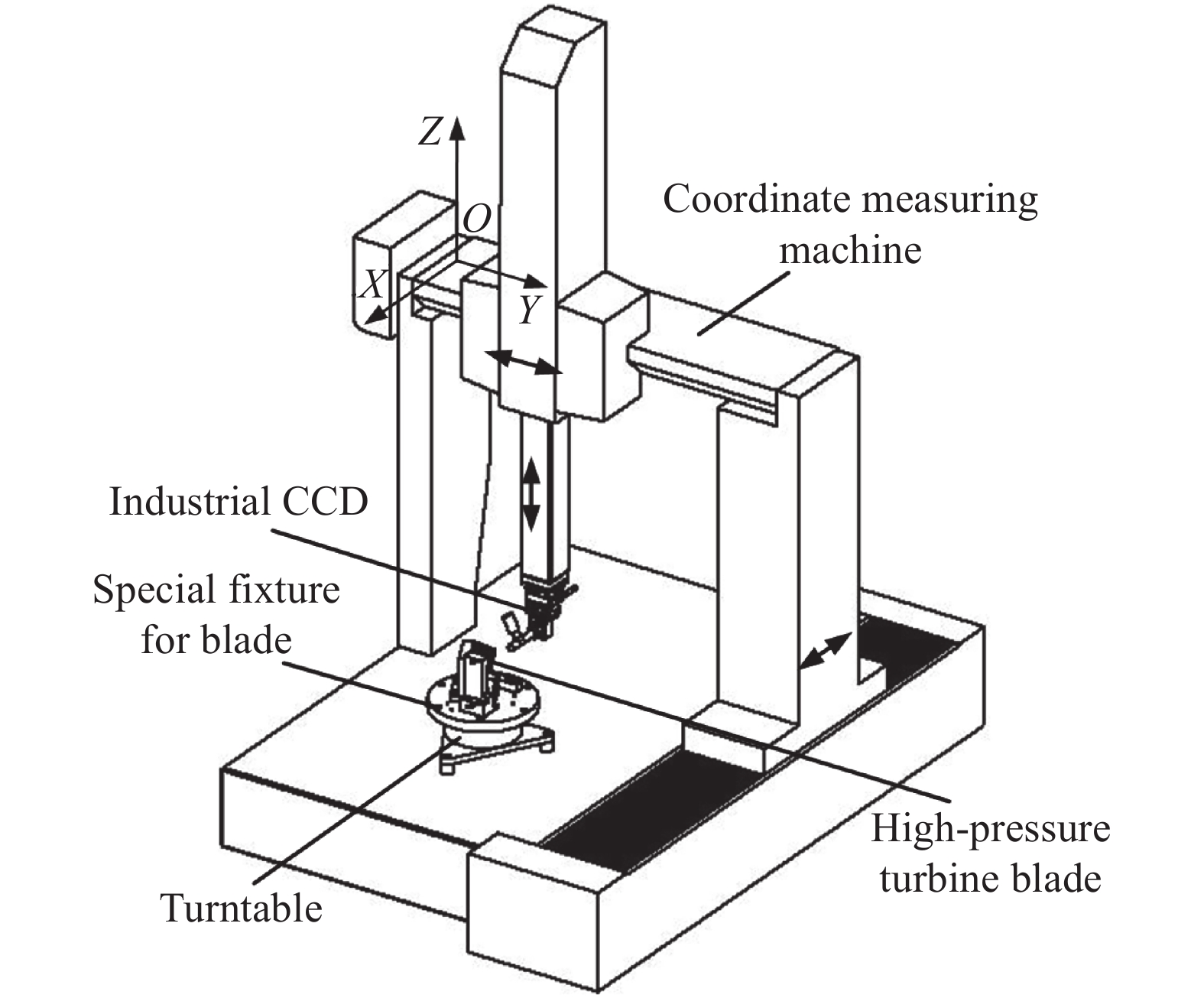
根据高压涡轮叶片上的气膜孔特征的分布特点与测量需求,文中应用三坐标测量机、工业影像测头、回转工作台和叶片夹具等设计并搭建了四轴视觉坐标测量系统,如图1所示,从而将三坐标测量机的移动范围大、定位精确和通用性强等优点与工业影像测头的非接触、信息丰富和应用灵活等优点结合在一起[10],并且增加了回转工作台(第四轴)以用于被测叶片的转位,从而为解决气膜孔加工过程中的量值传递与溯源难题提供了检测技术支撑。该测量系统的运动机构由X、Y和Z三个直线轴和一个回转轴构成。其中,X、Y和Z轴集成在一起,由三坐标测量机实现;而回转轴单独布置,由回转工作台实现;被测高压涡轮叶片则通过叶片夹具固定在回转工作台上。
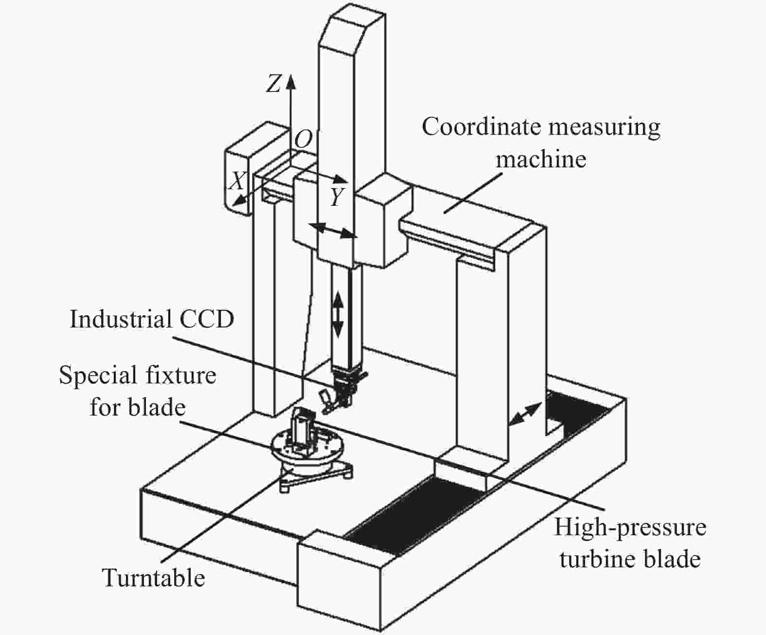
Figure 1. Composition diagram of the four-axis vision coordinate measuring system
在实际应用中,为了简化后续测量数据的坐标变换过程,首先通过机械调整使回转工作台的轴线处于竖直方位,即使其与三坐标测量机的Z轴相互平行,则此时回转轴线在机器坐标系O-XYZ中的单位方向向量被确定为(0,0,1)。因此,当回转工作台每旋转到一个角度位置时,由工业影像测头获取的被测零件上的这一部分测量数据,则只需要经过简单的平移、旋转等坐标变换就可以得到在旋转之前的数据,即将不同角度位置下的测量数据均转换到了统一的回转工作台坐标系中[11-12]。在这种情况下,通过回转工作台的连续旋转并辅以准确的数据整合算法,就可以最终将被测零件的全部测量数据转化到相同的坐标系中,从而实现四轴联动测量[13]。在这个过程中,还需要标定出回转工作台的轴线在机器坐标系O-XYZ中的位置,即确定出回转轴线的原点OR的空间坐标(X0,Y0,Z0),这是四轴联动测量功能实现的关键所在。
-
由于测量系统的前端传感器为工业影像测头,不同于常规的接触式测头与激光测头,其输出为被测物体的平面像或平面投影,并且对物体的棱边、尖角等突变部位较为敏感,因而更宜选用具有平面特征的物体来进行回转轴线的位置标定。因此,文中选用了定制的长方体标定块来实现回转轴线原点OR的空间坐标(X0,Y0,Z0)标定。如图2所示,该标定块的形状为长方体,采用特殊合金钢材料制作而成,具有良好的形状精度、尺寸精度和表面质量,并且各条棱边均为锋利直边,没有倒角,也未被倒钝。同时,为了获得较高的标定精度,标定块的厚度L和高度H均采用经过精密测量而得到的实测值。

Figure 2. Specially designed cuboid block
基于此标定块进行回转轴线的位置标定的步骤如下:
(1)回转工作台旋转到0°位置,将标定块放置在回转工作台的台面上,并借助于千分表或者电感测微仪等对标定块的方位进行机械调整,使标定块的厚度L所在的方向与机器坐标系O-XYZ的X轴平行,高度H所在的方向与Z轴平行,如图3所示。调整好标定块的方位后,为了防止其方位发生变化而影响标定结果,应用粘结剂将标定块暂时固接在回转工作台的台面上。
(2)由三坐标测量机的X、Y和Z轴带动工业影像测头运动,使其对焦于标定块的前表面(通过基于Laplacian算子的对焦评价函数判断),而后锁住X轴和Z轴,使工业影像测头只沿着Y轴移动,直到标定块的左侧棱边出现在工业影像测头的视场中,采集该棱边的图像,并记录此时X、Y轴的光栅尺读数为(X1,Y1),如图4所示;然后通过图像处理提取出该棱边在图像坐标系中的像素坐标,进而计算出该棱边与图像中心之间的像素距离la(单位:pixel),再与像素尺寸当量k(单位:mm/pixel)相乘,从而将像素距离la转化为物理距离a(单位:mm),即
Figure 3. Cuboid block after orientation adjustment
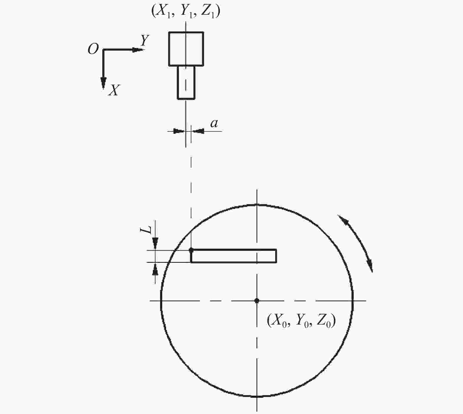
Figure 4. Image acquisition of the left edge of cuboid block
(3)回转工作台旋转到180°位置,并由三坐标测量机带动工业影像测头对焦于标定块的后表面,而后锁住X轴和Z轴,使工业影像测头只沿着Y轴移动,直到标定块的右侧棱边出现在工业影像测头的视场中,采集该棱边的图像,并记录此时X、Y轴的光栅尺读数为(X2,Y2),如图5所示;然后通过图像处理提取出该棱边在图像坐标系中的像素坐标,进而计算出该棱边与图像中心之间的像素距离lb,再与像素尺寸当量k相乘,从而将像素距离lb转化为物理距离b,即
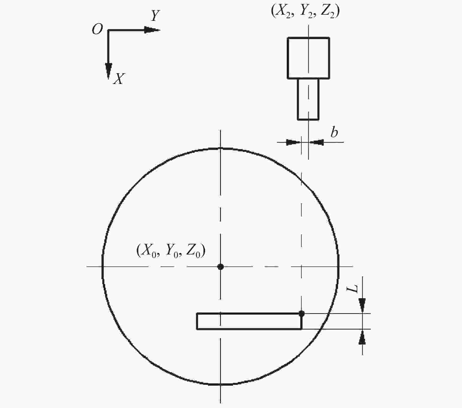
Figure 5. Image acquisition of the right edge of cuboid block
(4)对L、(X1,Y1)、(X2,Y2)、a和b进行代数运算,从而得到回转轴线的原点OR在机器坐标系O-XYZ中的X0坐标和Y0坐标,计算原理如图6所示。
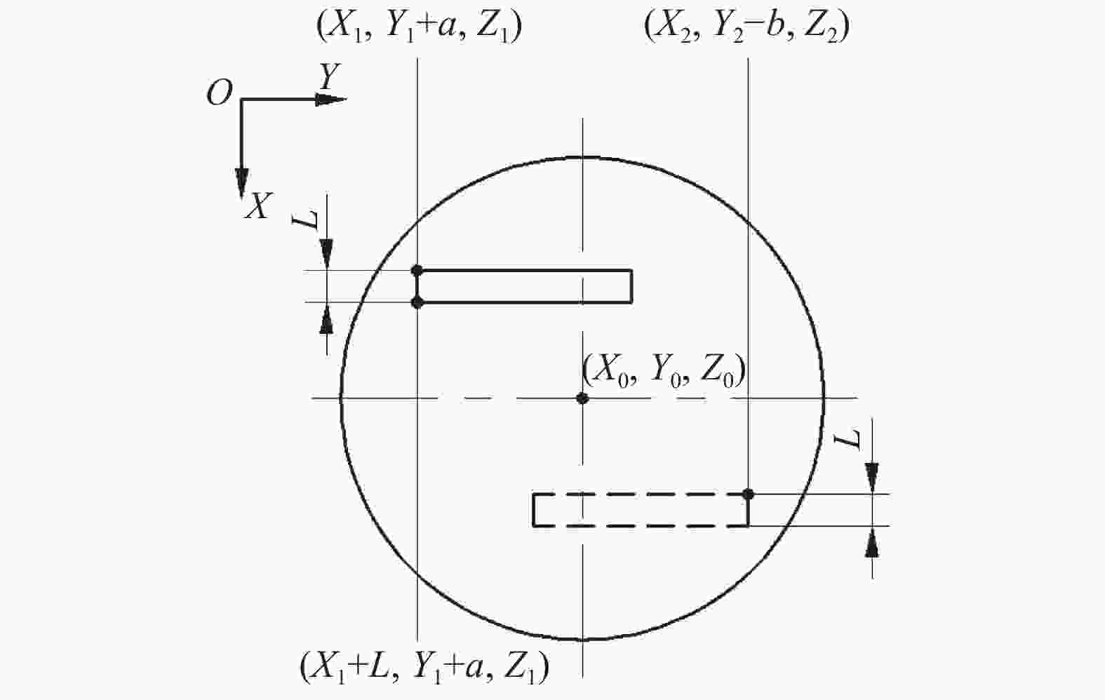
Figure 6. Calculation principle of X0 and Y0
(5)由三坐标测量机带动工业影像测头对焦于标定块的后表面,而后锁住X轴和Y轴,使工业影像测头沿着Z轴向上移动,直到标定块的上侧棱边出现在工业影像测头的视场中,采集该棱边的图像,并记录此时Z轴的光栅尺读数为Z3;然后通过图像处理提取出该棱边在图像坐标系中的像素坐标,进而计算出该棱边与图像中心之间的像素距离lh,再与像素尺寸当量k相乘,从而将像素距离lh转化为物理距离h,即
(6)对H、Z3和h进行代数运算,从而得到回转轴线的原点OR在机器坐标系O-XYZ中的Z0坐标,计算原理如图7所示。
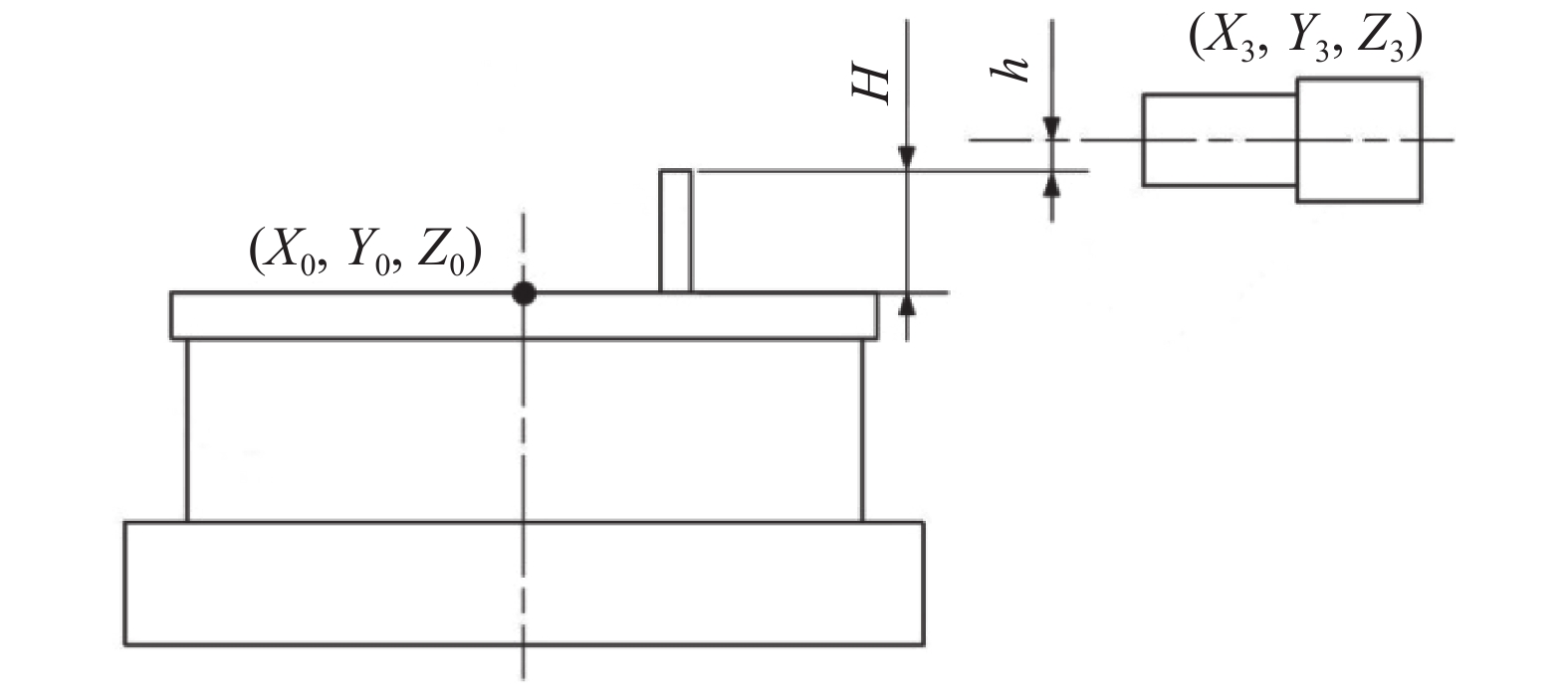
Figure 7. Calculation principle of Z0
通过以上步骤,即可确定出回转工作台的轴线原点OR在四轴视觉坐标测量系统中的三维空间坐标(X0,Y0,Z0),再结合上文所确定的轴线单位方向向量,从而完成了回转轴线的空间方位标定。这将有助于测量系统中的回转工作台坐标系的建立,并且可以进一步确立测量数据由机器坐标系到回转工作台坐标系的转换关系,从而为实现批量气膜孔特征的孔径、空间位置与轴线角度等形位参数的非接触式四轴联动测量奠定了基础。
-
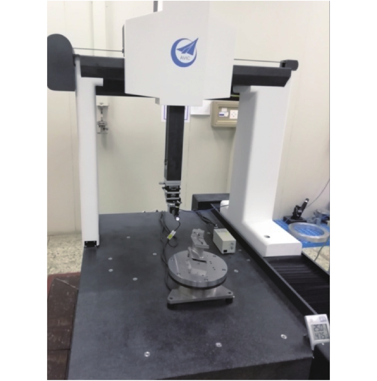
文中所搭建的四轴视觉坐标测量系统,选用北京航空精密机械研究所生产的PEARL 555型三坐标测量机作为系统平台,在其框架结构的基础上将工业影像测头安装在该型测量机的Z轴末端,以应对高压涡轮叶片上的气膜孔特征的形位参数检测任务,如图8所示。该型测量机采用先进的结构设计和工艺技术,轻便高效,其敞开的工作空间更具操作性,X、Y和Z轴均采用天然花岗岩,具有相同的热力学特性,同时采用内置钢丝的增强型同步带,使整机具有优良的动态性能,X、Y和Z轴的行程均为500 mm,各轴光栅尺的分辨率为0.5 μm,测量不确定度为(2.5+3×L/1 000)μm(L为测量长度)[14]。
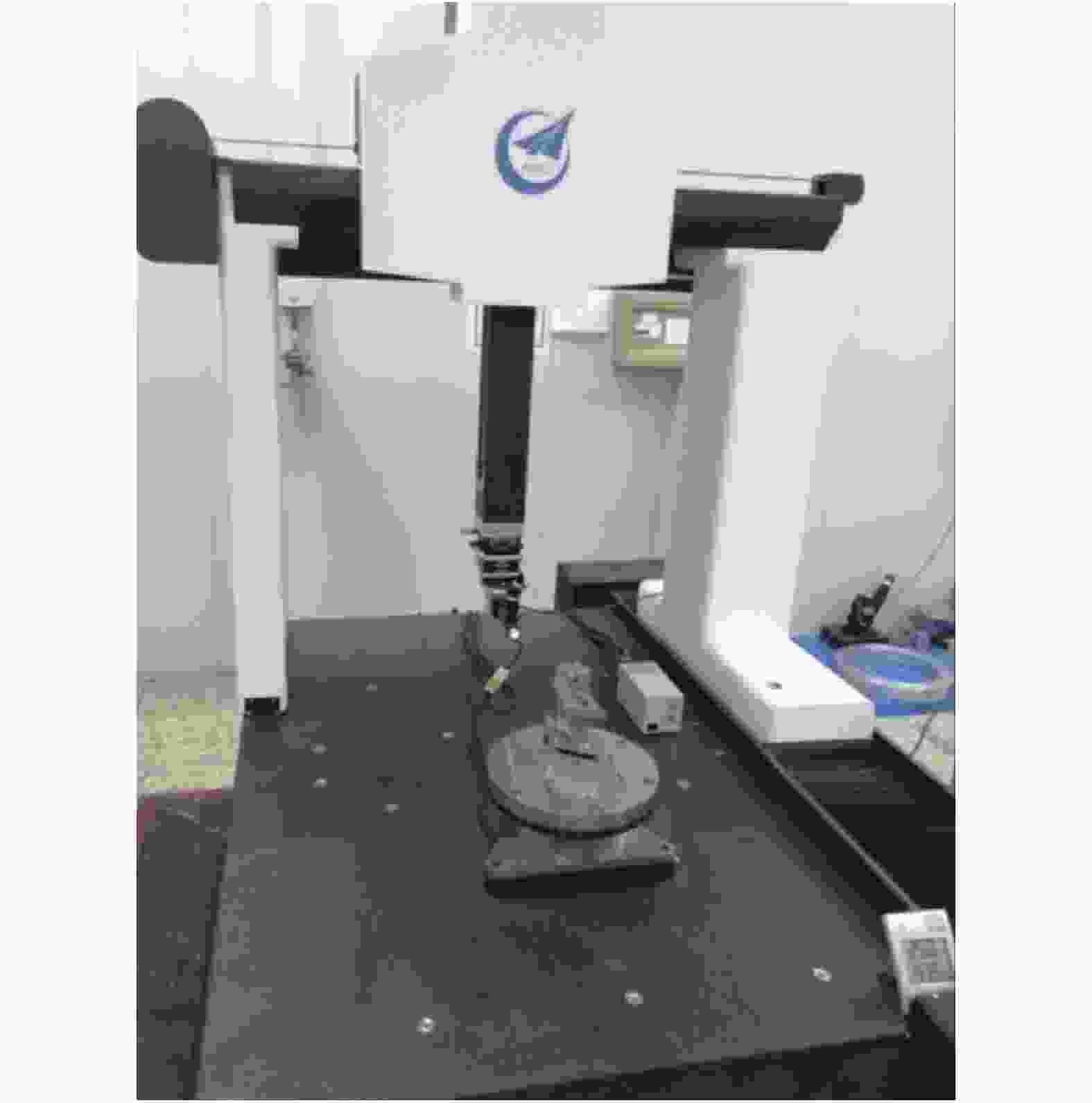
Figure 8. Four-axis vision coordinate measuring system
在回转运动方面,采用了日本Yaskawa公司的SGMCS型直接驱动伺服电机作为系统的第四轴,该型电机可以在不带减速器的状态下直接驱动负载,能够实现从低速到高速的强力平滑运行,并且内置了20位的高分辨率编码器,定位精度可以达到1'',因而可以用于将被测零件精确定位到所需位置[15]。
工业影像测头由工业相机、镜头与光源等组成。其中,工业相机选用大恒图像公司生产的水星MER系列工业数字相机,该型相机采用全局曝光的Sony IMX252 CMOS传感器,其分辨率为2 048×1 536,像素尺寸为3.45 μm×3.45 μm,并通过USB3.0数据接口进行图像数据的传输。为了配合该型工业相机的使用,选用了日本MORITEX公司的MML-ST系列工业远心镜头,该型镜头具有高对比度、高分辨率和低失真度的特征,其放大倍率为3倍,工作距离为108.3 mm,景深为0.44 mm。
-
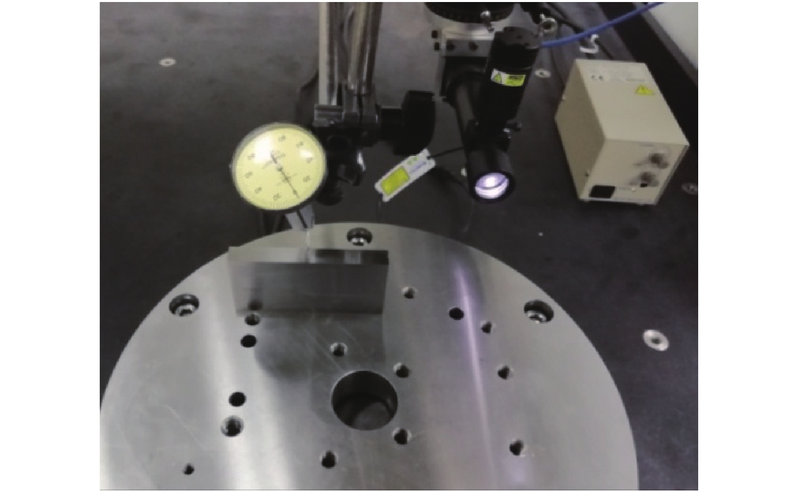
为了验证文中所提出的基于视觉测量的回转轴线标定方法的正确性和有效性,首先按照上文所述的标定方法和步骤,对回转工作台的轴线位置进行了标定。在标定过程中,应用千分表对标定块的方位进行机械调整的过程如图9所示;而控制工业影像测头对焦于标定块表面并采集其锋利棱边图像的过程如图10所示;最终采集到的锋利棱边图像及边缘提取结果如图11所示。

Figure 9. Orientation adjustment of the cuboid block
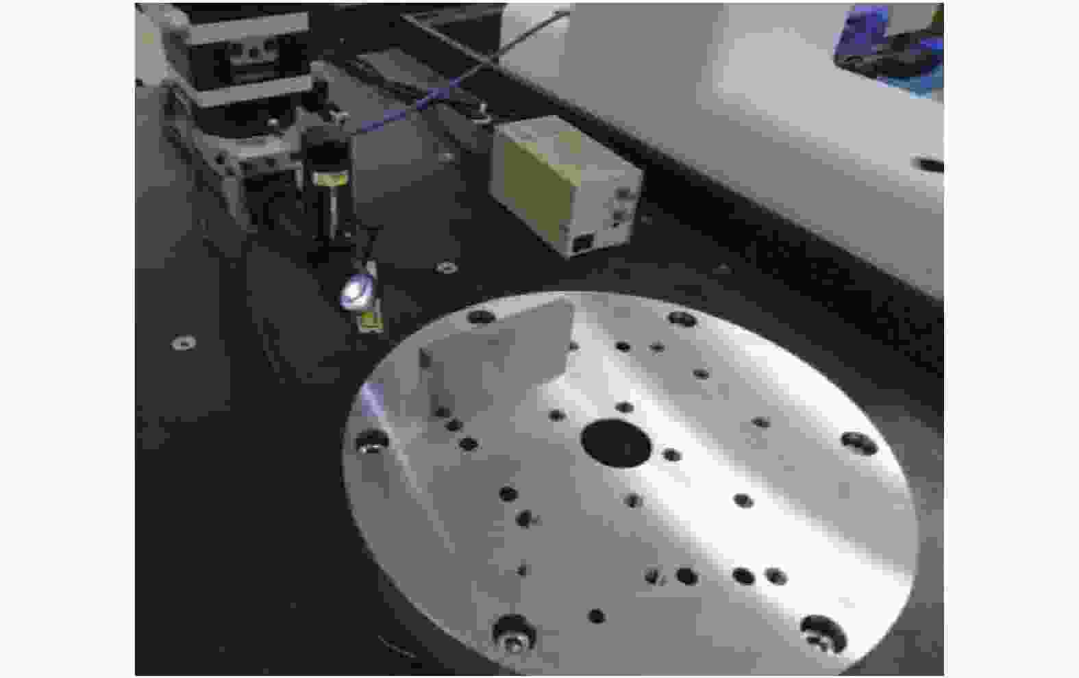
Figure 10. Focusing on the cuboid block surface and capturing the image of its sharp edges

Figure 11. Images of the sharp edges and edge extraction results: (a) Left edge; (b) Right edge; (c) Upper edge
根据公式(1)~(6),即可计算出回转工作台的轴线原点OR在机器坐标系O-XYZ中的三维空间坐标为(X0,Y0,Z0)。为了减小随机误差对标定精度的影响,文中采用多次标定实验的平均值作为最终的回转轴线位置标定结果,即(204.8 328,278.4 686,–10.2 804)。
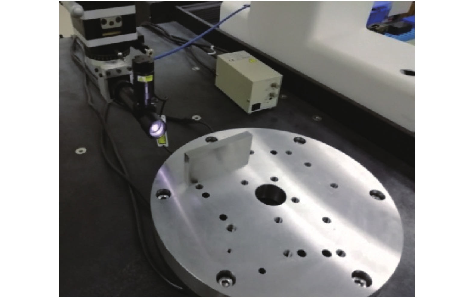
为了对该标定结果进行验证,文中选用了一个标称尺寸为80 mm的标准量块作为被测物体,应用所搭建的四轴视觉坐标测量系统分别对标准量块的两个被测面进行测量,并基于回转轴线位置的标定结果来获得两个被测面之间的距离,而后再与标称尺寸进行比对,通过测量误差的大小来检验标定方法及标定结果的正确性和有效性。实验现场如图12所示,连续对标准量块进行10次重复性测量,测量结果如表1所示。
No. Measuring results/mm Measuring errors/mm 1 80.006 0.006 2 80.008 0.008 3 79.995 −0.005 4 80.006 0.006 5 79.992 −0.008 6 79.993 −0.007 7 79.996 −0.004 8 80.009 0.009 9 80.005 0.005 10 80.006 0.006 Table 1. Measuring results

Figure 12. Experimental scene
从表1可以看出,应用回转轴线位置的标定结果,在对该标准量块的10次测量实验中,所测长度尺寸的平均值为80.001 6 mm,标准差为0.006 4 mm,并且各次测量结果与真实值之间的误差均小于±0.01 mm。影响标准量块测量精度的因素很多,必须进行详细分析,以确保测量结果的准确与可靠。在上述实验过程中,对合成标准不确定度影响显著的因素主要有:(1)测量重复性引起的不确定度分量;(2)三坐标测量机示值误差引起的不确定度分量;(3)对焦评价函数的判别误差引起的不确定度分量。
首先,对标准量块进行了10次重复性测量,则测量重复性引起的不确定度分量u1为:
其次,PEARL 555型三坐标测量机的示值误差为(2.5+3×L/1 000)μm(L为测量长度),在标准量块的测量过程中,三坐标测量机的最大移动范围为30 mm,则分布区间半宽a为:
设示值误差服从均匀分布,取包含因子k=
$\sqrt 3 $ ,则三坐标测量机示值误差引起的不确定度分量u2为:再次,文中应用基于Laplacian算子的对焦评价函数来使工业影像测头正确对焦于标准量块的被测表面。经过实验验证,该函数的对焦位置判别误差小于0.005 mm,则分布区间半宽为2.5 μm,设该误差服从均匀分布,取包含因子k=
$\sqrt 3 $ ,则对焦评价函数的判别误差引起的不确定度分量u3为:由于不确定度分量u1、u2和u3相互独立,因而标准量块测量结果的合成标准不确定度uc为:
实验结果验证了文中所提出的标定方法的正确性和有效性,可以满足了高压涡轮叶片上的气膜孔特征的形位参数检测需求。因此,文中所提出的标定方法,能够准确确定出四轴视觉坐标测量系统中的回转轴线的空间方位,从而为后续不同回转工作台角度位置下的测量数据的坐标转换奠定了基础,使其转换到同一坐标系下,以便于后续的数据处理;同时,回转轴线位置的标定精度也使系统能够满足其他回转体类零件的多轴视觉测量,从而提供了一种四轴视觉坐标测量系统下的回转轴线位置标定方法,解决了回转体零件的多轴视觉测量中的关键问题。
-
文中基于特殊设计的长方体标定块,提出了一种基于视觉测量的回转轴线标定方法,能够准确确定出四轴视觉坐标测量系统中的回转轴线的空间方位,从而将不同视角下获得的测量数据转化到同一个坐标系中以实现四轴联动测量。在标定过程中,首先调整好标定块的方位,然后通过控制回转工作台与三坐标测量机各轴的运动,使工业影像测头对焦于标定块的表面并采集其锋利棱边的图像,而后再通过边缘提取、像素距离计算、物理距离转化和代数运算等步骤,最终解算得到了回转工作台的轴线在机器坐标系O-XYZ中的空间方位。最后,通过多次测量一个尺寸参数已知的标准量块,各次测量结果与标称值之间的误差均小于±0.01 mm,充分验证了文中所提出的标定方法的正确性和有效性,从而为实现回转工作台坐标系的建立以及确立测量数据由机器坐标系到回转工作台坐标系的转换关系奠定了坚实基础。
Study on calibration method of rotary axis based on vision measurement
doi: 10.3788/IRLA202049.0413004
- Received Date: 2020-01-05
- Rev Recd Date: 2020-02-25
- Publish Date: 2020-04-24
-
Key words:
- vision measurement /
- coordinate measuring machine /
- rotary table /
- film cooling hole
Abstract: For the purpose of inspecting the film cooling holes on high-pressure turbine blade in a rapid and accurate manner, a non-contact four-axis vision coordinate measuring system was designed and established in the paper. With regard to the determination difficulty of the spatial location of the rotary axis, a calibration method based on vision measurement was proposed in the paper, which fully considered the imaging characteristics of industrial CCD used in the system. In the calibrating procedure, a specially designed cuboid mental block was applied as the target. Through the coordination between the turntable and the coordinate measuring machine, the industrial CCD focused on the block surface and then captured the sharp edges of the block. And then, the spatial orientation of the rotary axis in the machine coordinate system could be determined by edge extraction, pixel distance calculation, physical distance conversion and algebraic operation etc. Finally, a gauge block was selected to be inspected by the measuring system to verify the calibration method and results, whose nominal size was 80 mm. As the experimental results showed, the measuring errors were all smaller than ±0.01 mm. Therefore, the calibration method of rotary axis proposed in the paper showed higher calibration precision and repeatability, which could meet the inspecting requirements of the shape and position parameters of film cooling holes.


 DownLoad: