


-
在轨运行期间,卫星会受到轨道外热流(太阳直射、地球红外、地球反照)以及冷黑空间背景的交替加热和冷却,空间环境十分恶劣[1-3]。空间光学遥感器作为对地观测卫星的主要有效载荷,若直接搭载于卫星舱外,将直接暴露于恶劣的空间热环境,同时,还会受其内部热源(如各种电子设备、CCD组件等)热扰动的影响。若不对其温度加以控制,则无法保证遥感器各部组件正常工作必需的温度水平。因此,热设计是空间光学遥感器在轨性能的决定因素之一,是国内外热设计工程人员需重点解决的问题[4-8]。
某空间气体监测仪(简称监测仪)是我国首个专门针对温室气体遥感探测的载荷,主要功能是对全球主要温室气体CO2、CH4以及CO等气体柱总量进行探测,将在全球温室气体排放、温室气体源和汇分析、温室气体与气候变化等一系列科学问题研究中发挥重要作用。
监测仪结构布局紧凑,在较小尺寸空间内交错布置有8个镜头组件、11台电子设备,其中1个镜头组件上布置有2台电机。内热源数量众多,工作时间长,与光学镜头组件控温要求差异大,且其中1个电机工作时需二维转动。同时,监测仪位于卫星舱外,直接暴露于恶劣的空间热环境,且在卫星上处于不利于内热源散热的方位。上述这些特点使监测仪热设计难度较大。文中基于热管理[9-13]、间接热控[14]、辐射冷却及结构热控一体化设计等多种思路对监测仪进行热设计,并对热设计进行了热平衡试验验证。
-
监测仪包络尺寸(X×Y×Z):1 070 mm×930 mm×650.8 mm,由底板、外罩、遮光罩、光学镜头组件及各种信息处理器和控制器等11种电子设备组成,布局图(图1),电子设备E,光学镜头O,电机M。电子设备3~6分别安装在镜头2~5镜筒上,其余设备和镜头都安装在底板上。监测仪在卫星上的位置(图2)。表1为内热源热耗和工作时间,卫星轨道周期为102 min。
镜7为二维光学转动机构,镜7 CT轴布置1台步进电机,AT轴布置1台音圈电机。镜7工作时,AT轴音圈电机跟随镜框在CT轴步进电机带动下绕CT轴转动,同时,音圈电机转子转动带动镜体绕AT轴俯仰,音圈电机热耗集中在其转子线圈上,是二维转动热源。镜7组件及音圈电机结构示意图见图3。

Figure 1. Structure layout of gas monitoring sensor

Figure 2. Payloads' deployment on satellite
Calorigenic
equipmentsStand by
mode/WObservation
mode/WCalibration
mode/WOperating
time on
orbit/minElectric device 1 11 11 11 102 Electric device 2 0 3 3 68 Electric device 3 0 0.3 0.3 63 Electric device 4 0.9 1.2 1.2 102 Electric device 5 0.9 1.2 1.2 102 Electric device 6 0.9 1.2 1.2 102 Electric device 7 0 0 4 3 Electric device 8 0 20 20 63 Electric device 9 0 0 21.1 3 Electric device 10 8 8 8 102 Electric device 11 0 4 4 52 Voice coil motor 0 2 2 52 Stepper motor 0 1.7 1.7 52 Table 1. Heat consumption and operating time of calorigenic equipments

Figure 3. Schematic diagram of lens 7 components and voice coil motor
监测仪各部组件控温要求如表2所示。镜7组件位于入光口处,其镜体控温指标分为工作时和非工作时两种,非工作时指标要求相对宽松。电子设备3~6热耗集中在壳体内部的发热部件热端,发热部件热端靠耳片固定在壳体上,热端温度要求控制在0~20 ℃。
Components Temperature requirement/℃ Operating time Non-operating time Optical lens 7 19±3 19±7 Optical lens 1–6,8 20±2 Voice coil motor of optical lens 7 0–85 Stepper motor of optical lens 7 –10–80 Electric device 1,2,7–11 –10–45 Electric device 3–6 0–20 Table 2. Temperature control requirements of gas monitoring sensor components
-
监测仪结构布局紧凑,在较小尺寸空间内数量众多的光学镜头和内热源交叉并存,且光学镜头控温精度及稳定度要求较高,内热源控温范围则较宽。无论监测仪工作与否镜头1~6都要求控(20
$ \pm $ 2) ℃,镜头7在监测仪工作时要求19$ \pm $ 3 ℃;电子设备1、2、7~11要求−10~45 ℃,电子设备3~6要求0~20 ℃,音圈电机要求0~85 ℃,步进电机要求−10~80 ℃。在较小尺寸空间内控温目标不一致的光学镜头与内热源之间,存在直接或间接辐射换热,也存在直接或间接导热换热,若不采取合理措施,温度波动较大的内热源势必会影响光学镜头的高精度控温。此外,卫星平台上载荷数量较多,分配给监测仪的功耗及重量资源有限,监测仪自身内热源数量众多且功耗大,工作时间长,可用于热控的功耗就很有限;同时,监测仪位于卫星-Y侧,位于不利于内热源散热的方位,散热面资源紧张。这是因为卫星轨道为太阳同步轨道,+X飞行,+Z对地,轨道升交点地方时13:40。在此轨道上运行,卫星+Y侧为背阴面,始终不受太阳照射,是布置散热面的最佳方位,卫星-Y侧则长期受晒,不利于散热。限于卫星约束,监测仪散热面只能安装在监测仪本体,而监测仪位于卫星-Y侧,其+Y侧还有其它载荷,会受到其它载荷表面反射外热流的影响,因此,监测仪位于不利于内热源散热的方位,散热面资源紧张。
综上,采取何种热控措施,让控温精度较高的光学镜头组件与控温范围较宽的内热源同时满足温度要求,同时又节省热控功耗及重量资源成为监测仪热设计的特点及难点。
-
空间相机传统热控方案通常采用被动与主动相结合的原则,即合理开设散热面,将内部热源热耗排散出去,同时在相机主体适当区域采用主动加热的措施维持相机主体尤其是光学部分的温度水平,并且在内热源上布置辅助主动加热措施,在内热源不工作或散热面所受空间外热流较小时维持内热源的低温限。这种方案对热源种类单一,热源总功耗较小的传统空间相机比较适用,因为这种设计方式简单可靠,所用热控资源也少。但监测仪内热源数量众多,总功耗大且工作时间长,若仍采用传统热控方案,数量众多的内热源分别开设散热面,分别进行低温限补偿,对光学镜头直接进行主动加热控制,所需热控功耗以及散热面资源会比较大,与热控资源紧张冲突;同时,各自独立温度波动较大的电子设备温度势必对光学镜头温度造成多方位扰动,不利于光学镜头的高精度控温。因此,监测仪热控需采用新的思路。
热管理是随着空间飞行器大型化而提出的,其重要特点是从系统角度出发,对受控对象有关热环境和子系统的热行为进行统一调配与综合利用,以降低能源需求和系统重量[9-10]。近年来热管理也已在空间光学遥感器热控领域获得了应用[11-13]。因此,可基于热管理思路对监测仪进行热控设计。
首先,按照控温目标可将监测仪各部组件划分成两大控温区,即光学镜头控温区和内热源控温区。监测仪无热耗的结构件底板和外罩,除设置在外罩上的入光口外,可将光学镜头与外部恶劣热环境在空间上最大程度隔开。同时,众多光学镜头组件分散安装在底板上,底板与光学镜头之间不仅存在直接导热换热,底板温度变化产生的热变形也会引起光学镜头位置精度变化,进而对成像性能造成一定影响;而外罩则与所有光学镜头组件之间都存在直接辐射换热,对所有光学镜头温度都有直接辐射影响;因此需将底板和外罩均纳入光学镜头控温区,否则将很难保证光学镜头高精度控温要求。
电子设备3~6控温范围0~20 ℃,处于光学镜头控温区内,其控温范围除指标上限外,低于光学镜头的控温目标20 ℃,必须进行散热设计。基于热管理思路,必须将其与光学镜头控温区最大程度热隔离,包括导热热隔离和辐射热隔离。因为若不将其与光学镜头室温控温区热隔离,则光学镜头室温环境必通过其散热路径向外空间漏热,从而增大维持室温环境所需的主动控温功耗,造成资源浪费。同时,室温环境对其的漏热,则在一定程度上增加其辐射散热面的负担,从而在一定程度上增加辐射散热面的大小。
电子设备1、2、7~11控温范围-10~45 ℃,处于光学镜头控温区内,控温上限45 ℃高于光学镜头控温目标20 ℃,通过初步热分析可将这些电子设备分成2类。第1类电子设备在光学镜头室温环境下,不采取散热措施时,工作温度会超过其指标上限;第2类在光学镜头室温环境下,不采取散热措施时,工作温度距指标上限有一定安全预度。
基于热管理思路,对第1类必须进行散热设计,且基于热管理思路,该类电子设备必须与电子设备3~6分开散热,不共用散热面,而且需尽可能使其高温工况下实际被控温度高于光学控温区。基于辐射换热基本理论,散热面温度越高,单位面积散热面散热能力越大,与电子设备3~6分开散热后,该类电子设备散热面设计温度可高于电子设备3~6散热面的设计温度,从而节省散热面面积。而使其高温工况下实际被控温度高于光学控温区目标温度,一方面可提高其散热面设计温度,节省散热面面积,另一方面则可保证高温工况时这类电子设备向光学控温区传递一定热量,从而降低高温工况下光学控温区主动控温加热回路的占空比,在高温工况监测仪工作用电高峰时可在热控功耗方面可减少实际用电量。但为避免该类电子设备高低温工况交变时,因热耗变化和散热面外热流变化导致的较大温度波动对光学镜头控温造成不利影响,该类电子设备也需与光学镜头控温区进行最大程度热隔离。
基于热管理思路,对第2类有两种设计思路,第1种思路是强化其与光学镜头控温区之间的换热,增大吸收其热耗的热容,在拉低其温度水平的同时,将其热耗用于光学镜头控温区控温,在一定程度上节省光学镜头控温功耗;第2种思路是将其与第1类热导通,以便在第1类工作时,为第1类提供分担热耗的热容,节省第1类的散热面面积,同时,使两者组成的系统,具有较大的热容,节省低温工况补偿功耗。两种思路相比,文中选第2种。第1种思路,考虑到光学镜头的严苛温度指标,需考虑该类热源热耗在监测仪上的均布,需使用均温措施。第2种思路则无需考虑热耗的均布,因为所有电子设备温度指标范围都比较宽,与第1种思路相比,会在一定程度上降低热控布局难度。
初步热分析表明,在电子设备1、2、7~11中,电子设备7和9无需散热,其余电子设备都需散热。基于热管理思路将其分成2组在轨有长期热耗、热容较大的系统,然后再散热。电子设备1~2一组,其中电子设备1在轨有长期热耗;电子设备7~11一组,其中电子设备10在轨有长期热耗。电子设备1~2与电子设备7~11分开散热,是因在结构布局上,电子设备1~2位置临近,电子设备7~11彼此位置相互临近,而2组之间距离较远,布局导热热管难度较大。
音圈电机控温要求0~85 ℃,步进电机控温要求−10~80 ℃,控温上限均高于光学镜头控温目标20 ℃,初步热分析表明步进电机自身热容较大,功耗较小,仅1.7 W,无需对其散热,而且其位于镜头组件7CT轴末端,对所有光学镜头都不可见,包括镜头组件7的镜体,与镜头组件7的镜体也无直接导热路径,因此对其无需采取特殊热控措施。音圈电机热耗集中在转子线圈上,转子线圈质量约0.02 kg,热容很小,约7.7 J/K,功耗虽然不大,但仍需要采取散热措施。音圈电机线圈为二维转动热源,若采取导热换热方式对其散热,需引入二维转动挠性导热环节,实现难度大,会降低热控系统可靠性,且给二维指向机构电机增加额外负载。相比较而言,辐射冷却散热则简单可靠。因此,文中对音圈电机采取辐射冷却散热思路,避免在传热路径中引入转动环节,以提高热控系统可靠性。
对光学镜头控温区,基于热管理思路将其与内热源控温区最大程度热隔离后,为提高光学镜头控温精度,对光学镜头采取间接控温为主,主动控温为辅的热控方案。间接热控是通过对被控对象周围结构件进行主动控温,为被控对象提供良好温度环境,主要利用周围结构与被控对象之间的辐射换热来间接保证被控对象的温度。与直接在被控对象上施加主动控温功率相比,间接热控更有利于实现被控对象的高精度恒温控制[14]。因为采取主动加热控温措施时,受控温设备测控温精度的限制,被控对象温度会产生一定波动,而进行间接控温时,热量主要通过辅助控温结构与被控对象之间的辐射换热传递到被控对象,因主动控温导致的辅助控温结构温度波动则可由辐射换热作用起到消峰填谷效果,从而在保证被控对象控温水平的同时,可使被控对象温度在较小的温度范围内波动,从而提高被控对象控温精度。
上述热控方案中,电子设备内热源热容热耗的系统管理,转动电机内热源的辐射冷却,以及内热源控温区与光学镜头控温区之间的隔热,都需要在结构设计上进行实现,因此,需开展结构-热控一体化协同设计,主要是从热控角度对结构设计进行优化,如增强导热设计、增强隔热设计、增加辐射冷屏、在结构布局上通过导热元件热管实现对监测仪内热源热容及热耗的系统优化管理等。
综上,监测仪热控方案采用热管理、间接热控、辐射冷却及结构热控一体化协同设计等多种设计思路,整体热控方案如图4所示,监测仪各部组件详细热控方案将在后续章节给出。

Figure 4. Thermal control scheme of gas monitoring sensor
-
电子设备1~2和7~11散热方案如图5所示。电子设备1~2和7~11都与底板隔热安装,并在盒体表面包覆多层隔热组件(Multylayer Insulation,MLI)。电子设备与底板之间用螺钉连接,紧固螺纹在底板上,为增强隔热效果,对结构设计进行干预,不仅在电子设备安装脚与底板之间增加隔热垫,还在螺钉头部与设备之间增加隔热套筒,如图6所示,且螺钉使用钛螺钉。此外,在不影响成像性能的前提下,对结构布局进行合理干预,使电子设备7和8在结构布局上直接导热接触,并将尺寸较小的电子设备9,从安装在底板上,改为安装在电子设备8上。通过热分析进行反复计算,优化散热面面积。最终,高温末期工况下,电子设备温度在19~30 ℃之间;低温初期工况下,无低温补偿功耗时,仅电子设备1和电子设备10有长期工作热耗条件下,电子设备1、2和7~10壳体温度分别在11~14 ℃和1~11 ℃之间,都满足温度指标要求。

Figure 5. Heat dissipation schemes of electronic devices 1-2 and 7-11(E: electric device)

Figure 6. Insulation installation method between electronic devices and base plate
-
电子设备3~6内部发热部件仅靠尺寸很小的耳片安装在外壳上,接触面积小,仅有0.000 17 m2,而热管只能布置在外壳上,导致内部发热部件与散热面之间总热阻较大。为降低内部发热部件与散热面之间的总热阻,节省散热面面积,对电子设备3~6结构设计进行合理干预,在内部增加辅助导热铜片,该铜片一面与发热部件热端焊接成一体,另一面与设备外壳导热安装,使发热部件与外壳之间的接触面积增至0.001 m2。 电子设备3~6散热方案如图7所示。

Figure 7. Heat dissipation schemes of electronic devices 3-6(E: electric device; O: optical lens)
电子设备3~6直接安装在镜筒上,且面向镜筒的表面对镜头可见。为降低其温度对镜头温度的影响,对结构设计进行合理干预。要求其与镜筒之间隔热安装,隔热安装方式同图6。同时,要求其对镜头可见的表面低发射率处理,发射率不高于0.05,以降低该表面与镜头和镜筒内表面之间的辐射换热。此外,电子设备3~6壳体表面包覆多层隔热组件,使其与外罩、底板和其它光学镜头组件辐射热隔离。热分析表明,虽然设备3~5有在轨长期热耗,但仍需给该组内热源布置主动控温功耗。这是因为,一方面,该组热源外壳直接安装在镜筒上,且面向镜头的表面与镜头可见,不能与镜头之间完全绝热,因此,设备壳体温度不能波动太大,以免使镜头组件控温困难;另一方面,该组热源长期热耗较小,仅2.7 W,无法完全弥补轨道外热流周期变化和高低温工况变化造成的温度波动。
-
按照辐射冷却设计思路,音圈电机散热方案如图8所示。即在音圈电机附近位置布置辐射冷屏,辐射冷屏用热管与散热面相连。以尽可能增强辐射冷屏与音圈电机之间的辐射换热,同时,尽可能降低辐射冷屏对二维指向镜和周围室温环境的影响为原则,对辐射冷屏的尺寸、结构形式及安装位置进行结构热控一体化协同设计,且辐射冷屏面向音圈电机的表面发黑处理,红外发射率不低于0.85,其它表面则包覆多层隔热组件,并与底板隔热安装,隔热安装方式同图6。热分析表明,需在辐射冷屏上布置主动控温加热回路,以弥补空间外热流周期性及高低温工况变化带来的散热面温度波动,以保证辐射冷屏温度处在合适的范围内,在此范围内,辐射冷屏温度既对音圈电机有足够的辐射冷却作用,又不会对镜7镜体温度造成室温环境无法弥补的影响。此外,对音圈电机组件和镜体及镜框之间进行隔热设计,尽量降低音圈电机温度对镜体和镜框温度的影响。
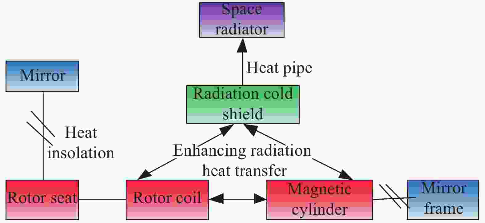
Figure 8. Heat dissipation schemes of voice coil motor
-
按照间接控温为主主动控温为辅的思路,光学系统组件控温具体思路为:在将内热源系统与底板、外罩和镜头组件最大程度热隔离的前提下,将外罩和底板温度控制在镜头组件要求的温度水平,为镜头组件提供良好温度环境,从而间接保证镜头组件温度水平,对某些间接热控效果不佳的镜头组件,再辅之于主动控温。
按照上述设计思路,首先,在底板和外罩外表面包覆多层隔热组件,并将底板与卫星平台隔热安装,外罩与遮光罩隔热安装,以尽量降低冷黑空间、复杂多变轨道外热流、星上其它仪器设备表面温度、遮光罩温度以及平台安装板温度等外部热环境对监测仪底板和外罩温度的影响。其次,在底板和外罩表面布置主动控温加热回路,为光学镜头组件提供良好的间接控温环境。为保证间接控温效果,在进行主动控温设计时,需合理划分控温区域,选取合适控温点位置及控温目标温度,并保证同一控温区域温度尽可能均匀。针对上述考虑,通过热分析手段,进行反复计算,调整优化,最终达到较优的控温效果。再次,在不影响成像性能的前提下,要求底板、外罩和光学镜头结构件表面发黑处理,红外发射率不低于0.85,以增强光学镜头组件与底板和外罩之间的辐射换热,保证间接控温效果。最后,由于光学镜头组件2~5与电子设备3~6直接安装,无法完全绝热,热分析表明,仅靠间接热控控温效果不好,需在其镜筒表面布置主动控温加热回路。
-
遮光罩无控温要求,但遮光罩安装在外罩上,且遮光罩内表面的部分表面对入光口处的镜头可见,需在遮光罩外表面包覆多层隔热组件,以尽量降低冷黑空间和轨道外热流对遮光罩温度的影响,从而尽量降低遮光罩在轨温度波动,同时,遮光罩与外罩隔热安装。热分析表明,遮光罩与外罩总热阻控制在180 ℃/W以内,在遮光罩附近的外罩上布置合适的加热功率,并选取合适的控温点,遮光罩无需额外热控措施,入光口处的镜头温度即可控住。
-
通过热平衡试验,获取在轨热边界条件下监测仪各部组件温度数据,对监测仪热设计进行验证。监测仪在轨热边界条件及模拟方法如表3所示。监测仪各部组件按照设计状态进行热控实施和总装。试验工况设置了低温初期瞬态工况和高温末期瞬态工况两种,如表4所示。
Thermal boundary conditions Simulation methods during ground test Vacuum and space cold black background Use space environment simulator Thermal environment on satellite platform Design simulation tool of satellite platform,which is shown in Fig.9, Fig.5
Control the temperature of simulation tool according to the given temperature boundary of satellite;
Cover simulation tool surfaces facing gas monitoring sensor with MLI and put heating circuit on surface of the MLI to obtain orbit heat flux absorbed by MLIOrbit heat flux Use infrared heating cage and flux sensor to abtain heat flux incidenting to the entrance of earth baffle;
Put heating circuit on MLI surfaces and radiator back surface to obtain orbit heat flux absorbed by themHeat consumption of calorigenic equipments Calorigenic equipments of gas monitoring sensor operate during test according to the normal working mode on orbit Table 3. Thermal boundary conditions of gas monitoring sensor on orbit and simulation methods of these conditions during ground test
Case Orbit heat flux One orbit working mode Temperature boundary
of satellite/℃Cold case Minimum heat flux throughout the life cycle Standby mode −5 Hot case Maximum heat flux throughout the life cycle Standby mode→calibration mode→
observation mode→standby mode45 Table 4. Operating conditions of test

Figure 9. Simulation tool of satellite platform
-
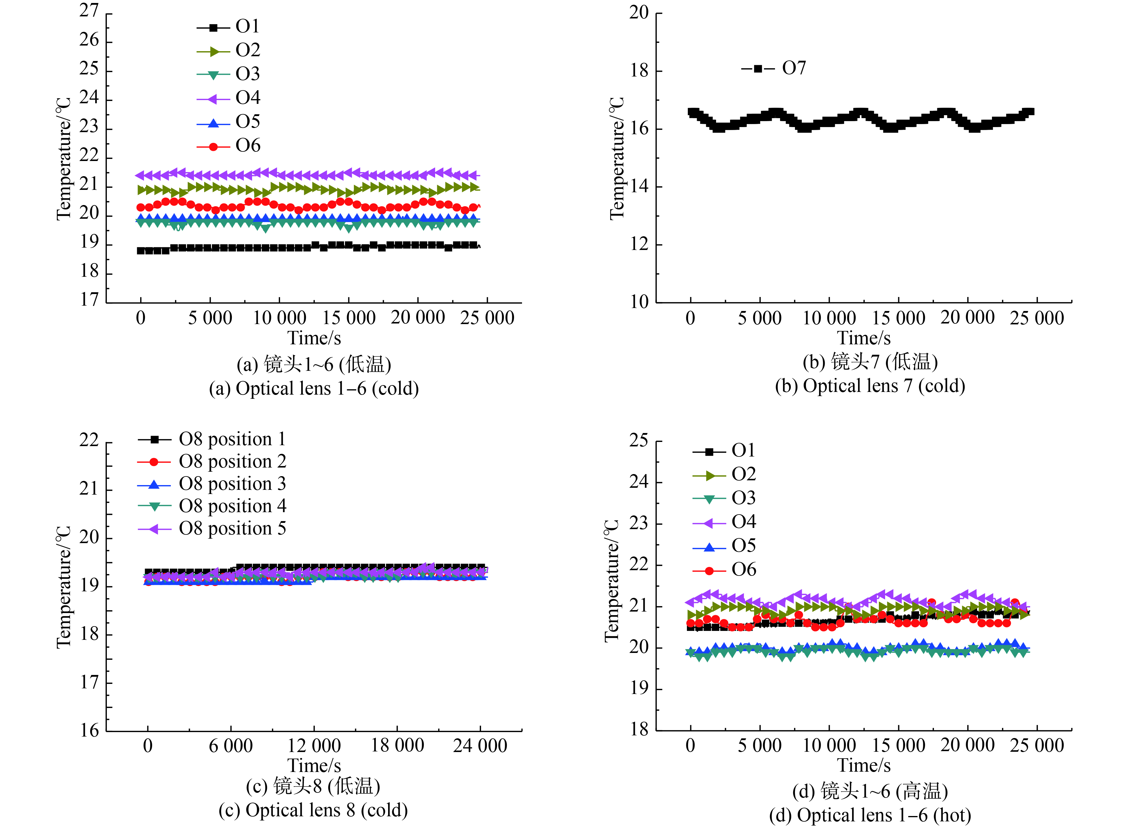
图10给出了低温初期瞬态工况和高温末期瞬态工况监测仪镜头组件连续四轨的温度曲线,表5对试验结果进行了汇总。由试验结果可知,整个寿命周期内,包括低温初期工况和高温末期工况,镜头7温度在16~20.3 ℃之间,其余镜头温度在18.8~21.5 ℃之间,电子设备3~6温度在8.4~12.8 ℃之间,其余电子设备温度在2.6~27.3 ℃之间,音圈电机和步进电机温度在14~36 ℃之间,均满足温度指标要求。由试验结果还可看出,整个寿命周期内,镜头温度稳定度较高。同一工况下,镜头最大温度波动都在1 ℃以内,高于指标要求的4 ℃。从低温工况到高温工况,除位于入光口处的镜7外,其余镜头最大温度波动都在2.1 ℃以内,也高于指标要求的4 ℃。镜头7位于入光口,受冷黑空间、轨道外热流以及遮光罩温度影响较大,且为给音圈电机散热,在其附近布置有辐射冷屏,导致其低温工况到高温工况温度波动相对较大,为4.3 ℃,但也在其工作指标允许的6 ℃以内。监测仪光学镜头组件温度较高的稳定度,主要归功于两点,一是采用了间接热控思路,二则是通过结构热控一体化设计,在结构上充分保证了内热源系统与光学镜头室温之间的最大程度热隔离,最大程度削弱了内热源系统寿命周期内的较大温度波动(20 ℃,见表5)对光学镜头室温环境的影响。

Figure 10. Temperature curves of main components on gas monitoring sensor under hot and cold case condition

Components Cold
caseHot
caseTemperature
requirementOptical lens 1 18.8−19 20.4−20.9 20±2 Optical lens 2 20.8−21.0 20.8−21.0 20±2 Optical lens 3 19.6−19.8 19.8−20.0 20±2 Optical lens 4 21.3−21.5 21.0−21.3 20±2 Optical lens 5 19.9−20.0 19.9−20.1 20±2 Optical lens 6 20.2−20.5 20.5−21.1 20±2 Optical lens 8 19.1−20.0 20.4−21.2 20±2 Optical lens 7 16−16.6 19.1−20.3 Operating time19±3
Non-operating time19±7Electric device 1 9.2−12 14.2−19.1 −10−45 Electric device 2 19.8−20.4 26.7−27.3 −10−45 Electric device 3 8.4−9.7 9.5−12.4 0−20 Electric device 4 8.8−10.0 9.9−12.8 0−20 Electric device 5 8.7−9.9 9.9−12.7 0−20 Electric device 6 8.4−10.0 9.5−12.8 0−20 Electric device 7 2.6−4.5 17.1−21.7 −10−45 Electric device 8 4.8−6.5 20.1−24.2 −10−45 Electric device 9 4.5−6.6 20.0−24.1 −10−45 Electric device 10 11.1−12.5 22.3−26.0 −10−45 Electric device 11 9.1−10.8 19.0−24.8 −10−45 Voice coil motor 14.4−16.3 17.9−35.6 0−85 Stepper motor 18.5−18.6 28.7−35.9 −10−80 Table 5. Summary of test results(Unit: ℃)
-
针对监测仪复杂的内外部热环境及光学镜头组件高精度控温要求,文中基于热管理、间接热控、辐射冷却及结构热控一体化协同设计等多种设计思路进行热控方案设计,有效解决了监测仪热设计难题,并对热设计进行了热平衡试验验证。试验结果表明:整个寿命周期内,包括低温初期工况和高温末期工况,镜头7温度在16~20.3 ℃之间,其余镜头温度在18.8~21.5 ℃之间,电子设备3~6温度在8.4~12.8 ℃之间,其余电子设备温度在2.6~27.3 ℃之间,音圈电机和步进电机温度在14~36 ℃之间,均满足温度指标要求;且整个寿命周期内光学镜头温度稳定度较高,同一工况下镜头最大温度波动在1 ℃以内,高于指标要求的4 ℃。从低温工况到高温工况,除镜7外,其余镜头最大温度波动都在2.1 ℃以内,也高于指标要求的4 ℃。镜头7最大温度波动为4.3 ℃,也在其工作指标允许的6 ℃以内,实现了多热源复杂工作机制下光学镜头高精度控温。试验结果验证了热控方案的正确性和有效性。
Thermal design of one space gas monitoring sensor and test validation
doi: 10.3788/IRLA202049.0413007
- Received Date: 2020-01-05
- Rev Recd Date: 2020-02-25
- Publish Date: 2020-04-24
-
Key words:
- space remote sensor /
- thermal design /
- thermal balance test /
- thermal management /
- indirect thermal control
Abstract: The structure layout of one space gas monitoring sensor is very compact. There are eight optical lens, eleven electronic devices and two motors staggered in the small-scale space. There were so many calorific equipments with long working hours and large power consumption, and their temperature control requirements were not consistent with the optical lens, the number of which was also large. Furthermore, one of the two motors was a two DOF turn motor during operating. These above characteristics make thermal design of the gas monitoring sensor a great challenge. To effectively solve the difficult problems of the gas monitoring sensor thermal design, combination of multy design methods were adopted. The thermal behavior of the gas monitoring sensor components were systematically managed based on the idea of thermal management to save thermal control resources. Indirect thermal control technology was used on the optical lens temperature control to guarantee meeting the high precision and stability requirement. Heat dissipation of the two DOF turn motor was achieved by radiation cooling, by which flexible rotating table could be avoided in the cooling path, so that thermal control system reliability could be improved. Finally, structural and thermal integrated design was applied to make sure the requirements of those above thermal design fully guaranteed in structure. The results of thermal balance test show that all components temperature meet the requirements no matter under cold case condition or hot case condition, and optical lens have high temperature stability throughout the life cycle. The maximum temperature fluctuation of all optical lens is less than 1 ℃ under the same case condition. High precision thermal control of optical lens are obtained under the condition of multiple heat source and complex working mechanism.


 DownLoad: