


-
随着空间遥感器分辨率和探测灵密度的不断提高,光学系统口径也越来越大,光学元件口径也相应增大,对其性能要求也越来越高。作为空间遥感器关键部件的各反射镜组件从研制到在轨使用的过程中,要能经受装调、力学试验、热试验、长途运输、发射和在轨运行的复杂环境考核,要求具有很好的热、力学性能,保证在地面装调及发射过程中承受超重和外界激励而不产生非弹性变形,甚至破坏[1-2]。因此,大口径反射镜的支撑结构具有良好的环境适应能力,是获取高品质和高稳定性空间遥感器的关键。
常见的反射镜支撑方式主要分为重力卸载支撑方式、主动光学支撑方式和被动支撑方式。重力卸载支撑难点在于精确卸载重力、卸载残余要足够小,设计与实现难度较大;主动光学支撑结构复杂,实现难度大,可靠性也不高;被动支撑方式较为成熟,结构简单,具有高可靠性和高稳定性,更易于实现轻量设计。主动光学支撑方式和重力卸载支撑方式多用于支撑1 m口径以上的大尺寸反射镜,小于1 m口径的反射镜更多采用被动支撑方式[2-4]。被动支撑方式作为最常用的反射镜支撑方式,国内外均有很成熟的研究及工程研制实例。国外,空间红外望远镜SOFIA反射镜采用侧面Bipod支撑、背部Whiffletree支撑相结合的方案实现空间六自由度限制;超新星加速探测器SNAP采用Bipod支撑方案实现主镜空间定位;国内,谭进国对适用于小口径反射镜的周边支撑技术进行了研究,面形精度RMS可达11 nm;任建岳、包奇红等采用背部中心支撑方案完成超轻量化圆形主镜装调;徐宏、关英俊等人采用背部三点支撑方案完成1 m口径反射镜支撑装调[5-7]。周边支撑简单方便,但对于大口径反射镜,会增加结构尺寸,不利于轻量化设计,也难以获得较高的面形精度。背部多点支撑容易获得较高面形精度,但结构复杂,体积大,质量大,还往往需要引入复杂柔性铰链系统,增加设计、加工、装调难度[8]。
文中设计了一种中心筒支撑配合四点热锁辅助支撑的大口径离轴反射镜复合支撑方案,在满足良好的加工、装配工艺性及轻量化设计要求的前提下,通过增加热锁辅助支撑,解决单中心筒支撑刚度较低的问题,同时在振动试验和发射主动段起到限幅作用,有效降低了力学环境下胶接应力对面形的影响。该方案应用于某空间遥感器的口径为706 mm×560 mm的离轴反射镜支撑设计,顺利通过力学试验,结果表明满足指标要求,验证了该支撑方式的有效性。
-
对于空间遥感器反射镜的稳定支撑,主要有两个支撑原则:一是对反射镜进行空间定位,确保反射镜在光学系统中位于确定的空间位置;二是保证镜体刚度,使反射镜组件的镜面面形精度满足成像的精度需求[9-15]。按照第一条原则,应该将反射镜看做一个刚体,采用依据机构运动学原理,约束反射镜的六个空间自由度,支撑形式应该为静定或超静定结构;按第二条原则,应该将反射镜视为弹性体,通过提升镜体自身刚度或者增加支撑点数来保证镜体自身变形最小,如采用轻量化结构来提高等效结构刚度、采用高刚度材料(如SiC)、增加支撑点数等来减小镜体弯曲变形。
-
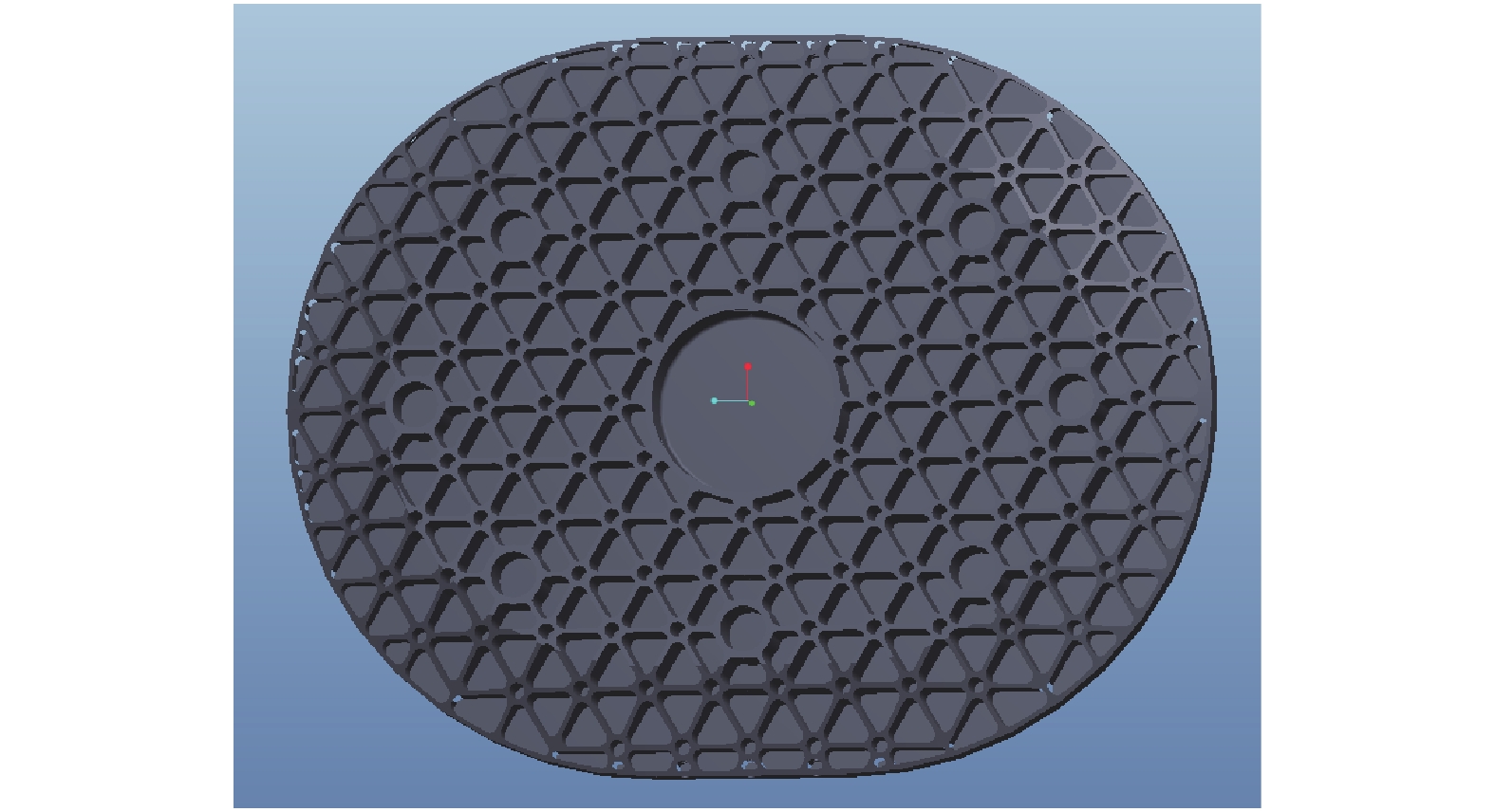
反射镜被动支撑方式一般包括装框式周边支撑、单点中心支撑、背部支撑和复合支撑等。装框式周边支撑较为成熟,主要适用于小口径反射镜的支撑;单点中心支撑一般适用于光轴竖直状态加工、使用状态任意的口径小于400 mm的反射镜;背部多点支撑一般适用于光轴竖直状态加工、光轴竖直状态使用的中大口径反射镜;复合支撑方式主要适用于光轴竖直状态加工、使用状态任意的中大口径反射镜[2]。文中论述的某空间遥感器的主镜为离轴非球面反射镜,口径706 mm×560 mm,采用SiC材料,光轴竖直状态加工,光轴水平状态检测及使用,要求组件装调完成后光轴水平(长轴与地面平行)重力作用、1 ℃均匀温升情况下面形变化RMS≤λ/100 (λ=632.8 nm),光轴水平状态检测时最终面形误差RMS值优于λ/40,基频高于120 Hz,静载30 g条件下胶应力≤3 MPa,组件质量不高于40 kg。主镜外形如图1所示。

Figure 1. Schematic diagram of primary mirror
该主镜选用的是背部敞开的轻量化结构,由三角形孔组成背部的网格结构。支撑结构选取上框式支撑,虽工艺成熟,但组件质量达48 kg,无法满足要求;背部多点支撑为多层桁架结构,型式复杂,导致工艺实施性较差,整体刚度也较低,预估质量约39.5 kg;单点中心支撑方式结构简单,质量轻,易于装配,但通过对中心支撑处胶斑应力分析发现,主镜组件受到30 g静载时,胶斑应力无法满足小于3 MPa的要求,计算数据见表1,需增加辅助支撑。
最终,在考虑尽量减重及工艺易实现性的前提下,提出了一种在单中心筒支撑的基础上对称增加四点可自由加、解锁热锁辅助支撑的新型复合支撑结构形式。既有效提高了单点中心支撑的抗力学性能,又保证主镜受力均匀,减少对面形的影响,组件预估质量38 kg,相比于传统框式结构降低了近21%,相比于背板多点支撑,装调工艺易实施性也得到提升,满足设计要求。
X Y Z 1 g gravity load 
Stress of glue spot 0.143 MPa
Stress of glue spot 0.172 MPa
Stress of glue spot 0.19 MPa30 g static load 4.29 MPa 5.16 MPa 5.7 MPa does not meet the requirement of less than 3 MPa Table 1. Simulation data sheet of gum spot stress in three directions supported by the center
-
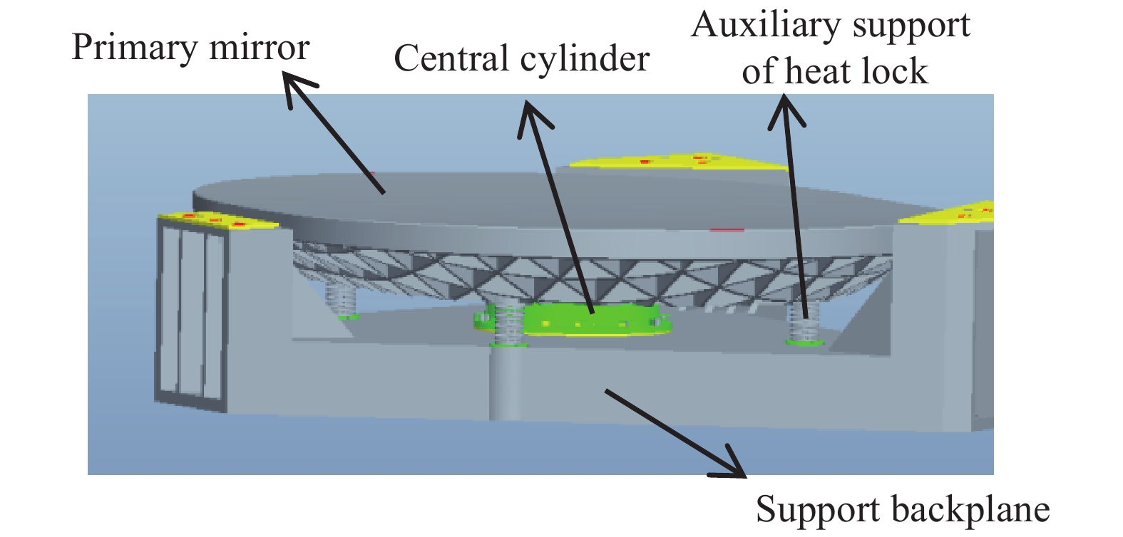
该主镜组件由主镜、中心筒、热锁辅助支撑及支撑背板构成,组件示意图如图2所示,采用中心筒支撑加四点热锁辅助的复合支撑方式。主镜、中心筒形成主镜部件,实现对主镜的定位支撑,不仅可以满足主镜支撑的支撑刚度和面形精度要求,同时该支撑方式结构形式简单、装调方便。长轴方向设计安装了四组热锁部件进行辅助支撑,热锁部件在力学试验和发射过程中锁紧、地面测试及在轨时释放,能有效提高主镜组件的一阶频率,降低主镜在力学振动试验及发射段力学响应放大倍数。

Figure 2. Schematic diagram of primary mirror assembly
-
中心支撑具有结构简单、质量轻、刚度高的优点,但在设计时也要考虑以下两点:(1)反射镜重心必须在中心支撑面内,即镜面以下,否则在重力作用下,镜面会产生像散;(2)因支撑零件与反射镜的线膨胀系数不同,在温度变化时会造成局部接触面应力增加,面形下降[9]。综合以上两点考虑及主镜镜体形式,主镜组件光轴水平时,支撑位置位于重心平面,能够获得最佳的重力变形面形精度,因此将中心筒胶接安装面设计在距主镜背部38 mm的主镜重心面处,如图3所示。主镜通过背部的中心孔与中心筒注胶粘接,中心筒材料选用与反射镜材料(SiC)线膨胀系数一致的超低膨胀合金——殷钢,避免热不匹配对主镜面形带来的不良影响。

Figure 3. Schematic diagram of center barrel assembly position
-
最小胶接面积根据Yoder公式初步确定:
式中:Qmin为最小粘接面积;W为光学件质量;aG为最恶劣加速度因子;fs为安全系数,大于等于2,保守取4;J为抗剪切强度,5 MPa。根据公式(1)计算得到主镜中心粘接面积Qmin≥5040 mm2。
-
主镜组件的性能指标主要包括约束模态频率、重力作用面形值、温度变化面形值、胶斑应力值等。灵敏性分析可以发现每个设计参数对主镜各个性能指标的影响程度,更进一步优化系统的性能。灵敏性分析首先需要将设计参数用变量vi(i=1, 2,···, n)来参数化,这样设计目标g与设计变量vi之间就构成了一个函数关系g=G(v1, v2, ···,vn),同时设计变量还要满足一定的约束方程fj=(v1, v2,···, vn)。优化的过程就是设计变量在满足约束方程和取值范围条件下,使设计目标达到最大或最小。文中主镜的结构参数优化数学模型可以表示为:
式中:
${g_{\min }}$ ——主镜面形值最小;$ {f}_{1}({v}_{1},{v}_{2},\cdots,{v}_{6})$ ——主镜组件基频大于120 Hz;$ {f}_{2}({v}_{1},{v}_{2},\cdots,{v}_{6})$ ——主镜组件在重力、1 ℃温升、强迫位移5 μm综合作用下面形值变化小于λ/100;$ {f}_{3}({v}_{1},{v}_{2},\cdots,{v}_{6})$ ——主镜组件质量小于40 kg;$ {f}_{4}({v}_{1},{v}_{2},\cdots,{v}_{6})$ ——主镜组件重力作用低头转角小于等于5";$ {f}_{5}({v}_{1},{v}_{2},\cdots,{v}_{6})$ ——主镜组件重力作用平移小于等于0.01 mm;$ {f}_{6}({v}_{1},{v}_{2},\cdots,{v}_{6})$ ——主镜组件胶斑应力值小于等于3 MPa;vi(i=1, 2,···, 6)——分别表示中心筒安装孔分布直径、中心筒壁厚、中心筒与背板安装法兰厚度、胶斑厚度、胶斑尺寸、胶斑面积。
若设计变量vi有一个很小的变化Δvi,设计目标也会有一个很小的变化,即
如果每个设计变量变化相同的值
$\Delta {v_i} = \Delta $ ,设计目标的变化量$\Delta g$ 是不同的,这样可以把$\dfrac{{\partial G}}{{\partial {v_i}}}$ 定义成设计变量对设计目标g的灵敏度。最终优化确定的中心支撑各参数数据如表2所示。
Parameter Distribution diameter of
center barrel mounting holeThickness of center
tube/mmThickness of mounting flange
of center cylinder/mmThickness of the glue
spots/mmGlue spot
size/mmArea of the gum
spot/mm2Data Φ138 5 7 0.1 Φ32 8591 Table 2. Table of parameters of the center support structure
-
对中心筒的结构优化设计后进行了主镜组件的光轴水平重力分析。中心筒连接面处在主镜重心平面处,因此主镜组件在光轴水平重力作用下面形精度变化较小,为0.002λ,满足指标要求,如图4所示。

Figure 4. Surface shape analysis of the primary mirror under gravity
约束主镜背板与主框架三处连接面处节点平动自由度,分析主镜组件无热锁状态下的一阶模态为132 Hz,满足基频大于120 Hz的要求,如图5所示。

Figure 5. First order mode cloud map of primary mirror assembly
-
热锁辅助支撑在设计时需考虑具备以下功能:
(1) 热锁锁定状态提供一定锁紧力,有效提高主镜组件的刚度;
(2)热锁锁定、解锁原理简单可靠,能实现反复锁定解锁功能;
(3)热锁锁定、解锁动作中,不产生冲击效应;
(4)热锁锁定、解锁作动元件便于获取,作动控制方式使用已成熟的控制手段。
依据热锁辅助支撑功能要求,设计了基于挤压力锁定作动原理的热锁结构,锁定原理示意图如图6所示。

Figure 6. Schematic diagram of working principle of hot lock
热胀杆为热膨胀系数较高的金属材料,外筒为热胀系数很小的金属材料,安装时热胀杆与外筒间保持微间隙配合,两者之间处于脱离状态。地面力学试验和发射状态加热热胀杆,热胀杆膨胀,热胀杆与外筒相互压紧,形成过盈配合结构,实现锁定功能;入轨后停止加热,热胀杆收缩,外筒与热胀杆脱离,实现解锁功能。最终完成的热锁组件设计如图7(a)所示。

Figure 7. Schematic diagram of hot lock assembly
热锁组件主要分两大部分:胶座、对箍、热胀杆形成一个固定结构,等效原理图中的热胀杆;嵌套、消热环、力环等效原理图中的外筒。非锁紧状态,胶座、对箍、热胀杆与主镜背板胶接固定,嵌套、消热环、力环与主镜胶接固定,两部分之间是分离的。锁紧状态时,热胀杆受热膨胀,热胀杆与力环形成过盈配合锁定,两部分形成一个整体零件,对主镜进行辅助支撑。通过中心镂空式结构的消热环设计来减小传热面积,增加到主镜的热阻,降低热锁温度对主镜的影响,如图7(b)所示。热胀杆两侧贴加热片及热敏电阻进行测温控温。将加热回路和热敏回路引入温控仪,预置热胀杆的温度。可由配合间隙实测值初步估算一个结果,计算公式如下:
式中:ΔH是配合间隙实测值;α是铝材料的热胀系数,为23.3E-6;T是热胀杆的预置温度。
-
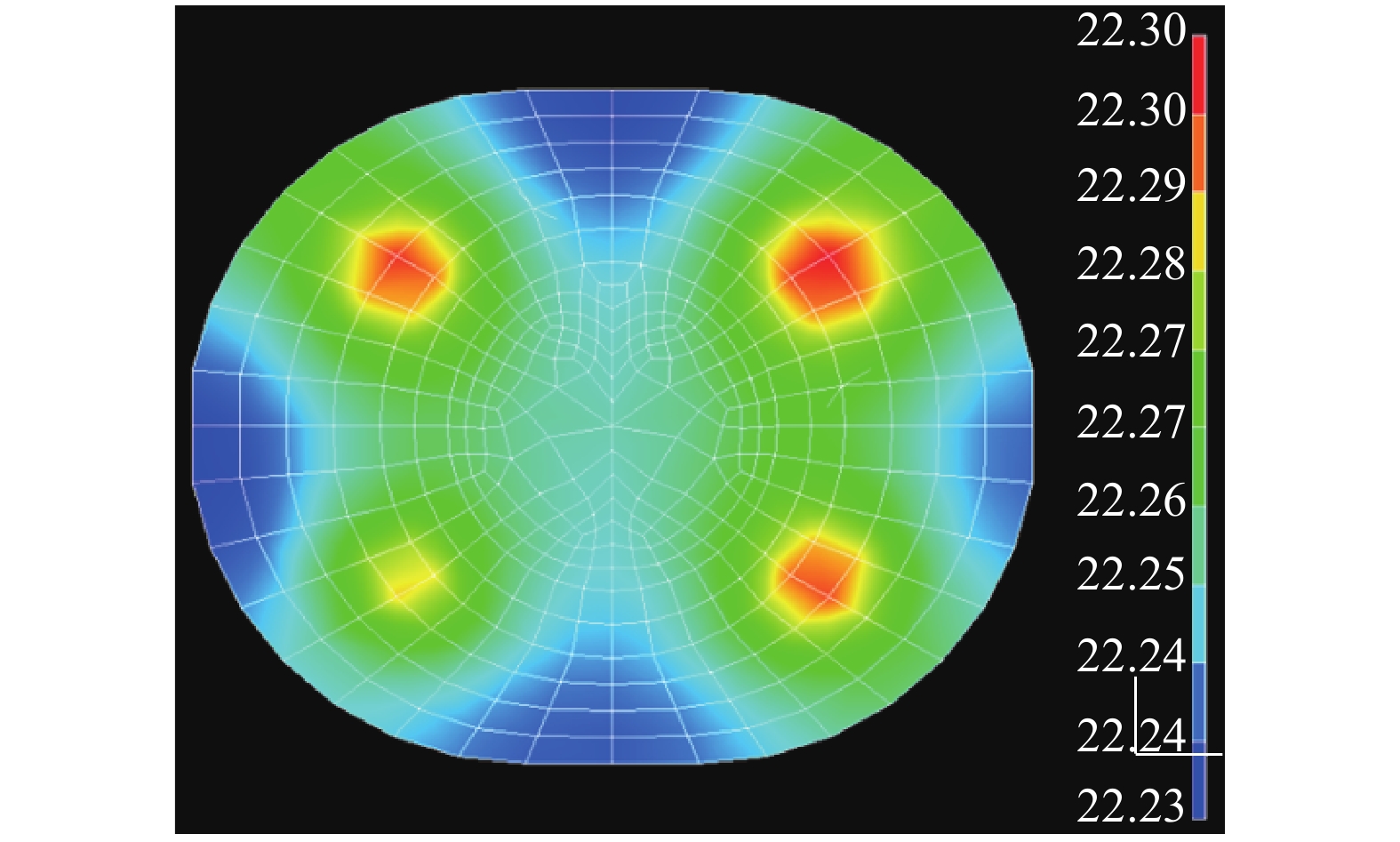
在实际工作中热胀杆确定的温度为(60±1) ℃,该温度在相机发射阶段保持3 h,热分析可将之等效为热稳态分析。考虑到解锁后应尽量减少主镜回温时间,要求热锁工作期间主镜温度不超过25 ℃。以主镜外部环境为21 ℃,黑背景、无遮挡、计算热胀杆温度60 ℃时,传到主镜处的温度如图8所示。四个热锁同时工作,稳态下镜面最高温度22.3 ℃,温差0.07 ℃,效果良好。

Figure 8. Temperture map of primary mirror
主镜组件工作状态的温度要求为(21±1) ℃,热锁工作时,虽然镜面最高温度超出主镜工作温度要求值0.3 ℃,但此时相机为非工作状态,故不会产生不利影响,且满足热锁工作时主镜温度不超过25 ℃的要求。当热锁解锁后,主镜温度会逐步恢复到21 ℃的工作温度,并由热控措施保证其温度稳定在±1 ℃范围内。
-
设计完成的采用中心筒支撑+四点热锁辅助支撑的主镜组件如图9所示。根据SiC的膨胀系数,定制了与其膨胀系数匹配的4J32殷钢作为中心筒材料,通过调整其中的微量元素,使殷钢的线膨胀系数可以与SiC非常接近,为2.5E-6/℃。

Figure 9. Diagram of primary mirror component
-
有热锁时主镜组件前六阶模态频率如表3所示。增加热锁辅助支撑后,主镜组件一阶模态由132 Hz提高到227.7 Hz,提升了抗力学性能。
Modal First order mode Second order mode Third mode Fourth mode Fifth mode Six mode Data 


227.7 Hz 269.6 Hz 273.3 Hz 332.1 Hz 475.8 Hz 478.1 Hz Table 3. Modal analysis table for primary mirror assembly (including hot lock)
-
有热锁时主镜组件1 g重力作用下三个方向胶斑应力计算数据见表4。
X Y Z 1 g gravity load 
Stress of glue spot 0.094 MPa
Stress of glue spot 0.092 MPa
Stress of glue spot 0.0885 MPa30 g static load 2.847 MPa 2.766 MPa 2.655 MPa It meets the design requirements of less than 3 MPa, and the stress state of the adhesive layer is effectively improved Table 4. Simulation data table of three directions of adhesive spot stress (including thermal lock)
-
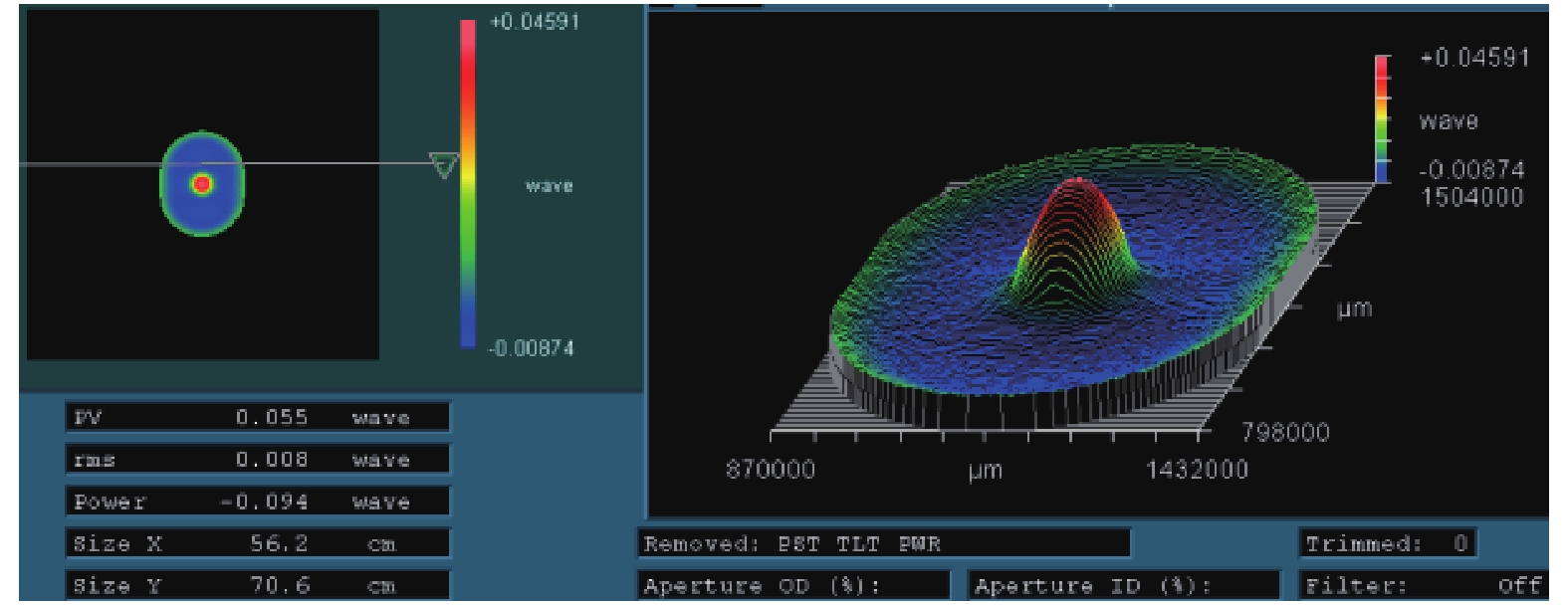
约束主镜背板三处凸台节点平动自由度,均匀温升1 ℃时主镜面形RMS变化0.008λ,满足RMS变化优于λ/100的要求,如图10所示。

Figure 10. Surface shape change of the primary mirror component with uniform temperature rise of 1 ℃
-
该主镜组件完成装调后,整个组件质量38.3 kg,满足不高于40 kg的要求,数据见表5。
Material Weight/kg Primary mirror SiC 16.7 (Lightweight:74%) Central cylinder 4J32 1.81 4 hot lock assembly 4J32, Al alloy 1.28 Support backplane SiC/C 18.51 Total weight 38.3 Table 5. Weight data table of primary mirror assembly
-
针对主镜组件的面形精度指标要求,采用ZYGO干涉仪对主镜组件不同阶段的面形进行了检测,结果表明主镜组件在热锁反复锁紧解锁试验及振动试验前后面形稳定,RMS变化小于0.003λ,且均满足RMS优于λ/40 的要求。面形数据见表6。
Experimental stage After assembly After locking and unlocking the hot lock for many times After vibration test Data 


Table 6. Surface data table of primary mirror assembly
-
为验证主镜组件的动力学特性,对其进行了力学振动试验,并在振动前后进行了三个方向的0.2 g的特征级扫频,试验数据如表7所示。结果表明,有热锁辅助支撑的主镜组件基频是200 Hz,与仿真结果基本一致,远高于设计要求的120 Hz;在振动试验中各点主振方向响应与输入一致,无放大,其他方向响应均小于主振方向;振动前后0.2 g特征级扫频各测点均无频漂,响应保持稳定。
X Y Z Sinusoidal response curve 


0.2 g sweep curve 


Table 7. Table of mechanical test data of primary mirror assembly
-
文中讨论了离轴反射镜高稳定性支撑问题,提出了一种在传统单中心支撑基础上增加四点可自由加、解热锁辅助支撑的大口径离轴反射镜新型复合支撑方案,是一种被动式主支撑+主动式辅助支撑的新型支撑设计。有效减轻了组件质量,并通过增加热锁辅助支撑改善胶层受力状态,提升了反射镜组件基频及抗力学性能。采用该支撑方式,运用有限元仿真分析方法完成了某空间遥感器706 mm×560 mm口径离轴主镜的设计及装调,并开展相应环境验证试验,结果表明主镜组件在加锁后动态性能优良,满足基频大于120 Hz、静载30 g条件下胶应力≤3 MPa,面形RMS优于λ/40的研制要求,验证了该设计的有效性,可应用于同类型反射镜的支撑结构设计与研制。
Design and verification of four auxiliary support points by heat lock for large aperture off-axis mirror
doi: 10.3788/IRLA20210007
- Received Date: 2021-01-04
- Rev Recd Date: 2021-03-30
- Publish Date: 2021-05-21
-
Key words:
- off-axis mirror /
- space remote sensor /
- high stability /
- heat lock /
- composite support /
- dynamic performance
Abstract: Aiming at the requirements of high surface accuracy, high reliability and high stability of large aperture off-axis mirror assembly, a new type of composite support scheme for off-axis mirror was designed, which was supported by central cylinder and four points that could lock or unlock freely. The heat locking parts were locked during mechanical test and launching, released during ground test and on orbit. It could effectively improve the fundamental frequency and the ability to resist vibration, while ensuring the surface quality. In the end, the design was verified in the development of 706 mm×560 mm off-axis mirror assembly of a space remote sensor. The results show that the dynamic performance of the mirror assembly is very excellent when the four auxiliary support points is locking, that can meet the requirements of adhesive stress ≤3 MPa when the fundamental frequency is greater than 120 Hz and the static load is greater than 30 g, and the RMS of the surface of the mirror is better than λ/40 (λ=632.8 nm) when the four auxiliary support points locked or unlocked. The support design is reasonable and effective.


 DownLoad: