


-
随着高功率的半导体激光器在各个领域的广泛应用,其对散热系统效率的需求和散热方式的要求越来越高[1]。传统的激光器散热方式有空气对流散热、半导体制冷散热、大通道水冷散热、微通道散热、热管散热等[2-3],其中大通道水冷散热方式具有结构加工简单,对冷却液要求低、可靠性高、水冷系统简单、机动性好等优点,是应用较广的激光器散热技术。目前已有较多针对大通道水冷散热技术的研究,Heng Zhao等[4]基于大通道水冷散热方法设计了两种S型通道结构,通过实验验证加圆柱形扰流柱散热效果更佳,并依据实验数值模拟得出0.011 L/s的最佳流速;刘刚等[5]在水流通道内部设计了交叉排列和正方形排列的圆柱,在芯片表面的平均热流密度为100 W/cm2时,通过实验与空腔结构对比,得出扰流结构的散热效果优于空腔结构,但会增加通道内压力的损失;梁雪艳等[6]针对流体通道结构设计,提出了中间入口的S型通道、双S型流体通道和中间入口的双S型通道三种结构的水冷板,并通过仿真得出中间入口双S型通道结构的综合性能最好。上述研究主要集中在结构设计和尺寸设计上,对流体特性分析相对较少。
由于流体通道多为矩形腔结构,冷却液在通道内流动时会产生湍流旋涡和湍流空洞,出现靠近热源的上层冷却液填充不充分和局部冷却液流速较低的情况,对激光器性能产生很大影响。第一,致使局部温升过高,使半导体激光器输出功率降低;第二,CS封装半导体激光器温度分布不均匀会导致热沉产生热应力变形,使bar条出现“Smile”效应,影响激光器光束质量[7-9];第三,会使冷却液在通道各处所受压力不均匀,导致冷却液中会有气泡频繁的产生和破裂,形成空泡腐蚀现象,使金属表面粗化,影响水冷结构的密封可靠性。
文中在冷却液流体特性分析的基础上提出了一种非典型宏通道结构的优化模型,通过数值模拟分析了优化模型与传统模型的流道中冷却液流动情况和流道中上层冷却液流速情况,使用Fluent软件对两种模型工作时的激光模块进行热分析,最后用两种结构的水冷系统对激光器进行散热实验,验证了优化结构的可行性。
-
散热系统基于CS封装的bar条半导体激光器进行设计,系统共分为两个模块进行装配,每个模块上安装4个bar条,共8个。单个bar条工作温度范围是20~35 ℃,最高设计温度不得超过40 ℃。首先依据传统矩形腔结构的流体通道设计了一套水冷散热系统经典模型,结构如图1所示。
系统的流体通道采用各模块和水冷底板密封贴合构成,其中进水口和出水口为直径12 mm的圆形通道,水冷底板中的矩形腔通道尺寸分别为宽15 mm、高10 mm,各模块的入水口和出水口与水冷板孔径匹配,矩形通道尺寸宽为12 mm,高为18 mm。冷却水的流动方向是从进水口进入水冷底板,然后自下而上进入Z01模块水冷板,流经Z01模块后回到水冷底板,再以同样方式流经Z02模块,最后从出水口流出。由于单个模块需要使用两种波长的bar条进行光学系统搭建,为配合光学器件的安装位置,各个bar条安装位置较为分散,位置见图1。流体通道走向除了需要跟随热源的位置外,还需避开其他光学器件位置,以免冷却液对水冷板冲击产生应力形变影响光学器件精度,因此流体通道在设计时走向较为曲折复杂。
冷却液在流经复杂的流体通道各处时所受的压力不均匀,当冷却液自下向上进入各模块时,在各模块入口处会产生较大水流旋涡,甚至会出现水流空洞现象。此外,流道的拐弯处侧壁曲度较小,冷却液流经各拐弯处时无法完全填充流道,使得流道内有气泡产生。以上现象不仅会增加流体通道内部空泡效应,影响散热系统可靠性,还会使流道上层冷却液填充不完全,局部冷却液流速太低,导致热源传导下来的热量无法及时被冷却液带走,影响激光器输出功率和光束质量。这种现象在文中的对比实验中也得到了验证(激光器工作时,使用红外测温仪观测到在热源1处和热源3处出现了散热效果较差的问题),进一步验证了经典模型中存在的问题,因此需要对经典模型进行优化设计。
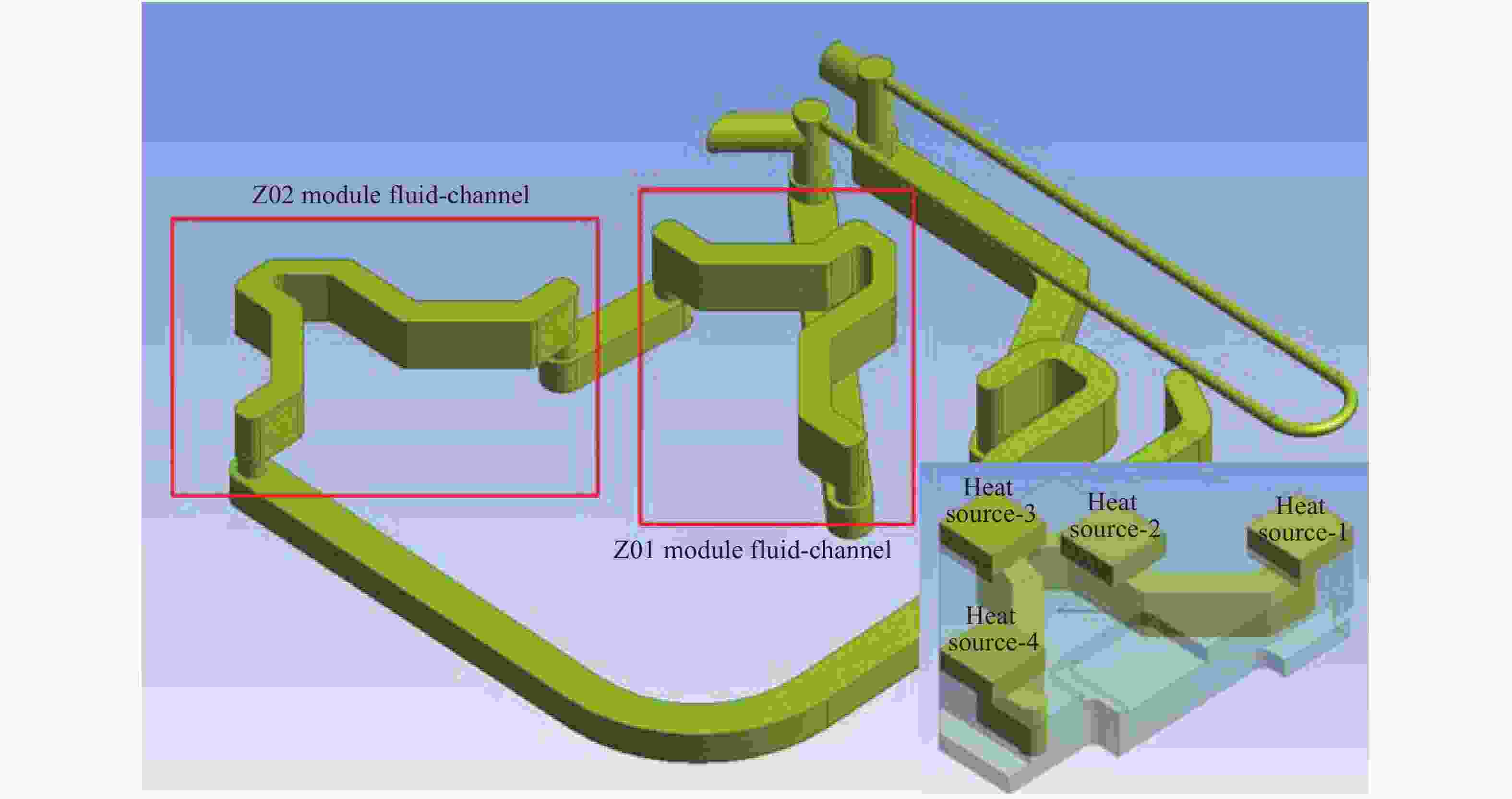
Figure 1. Rectangular cavity structure of classical model
-
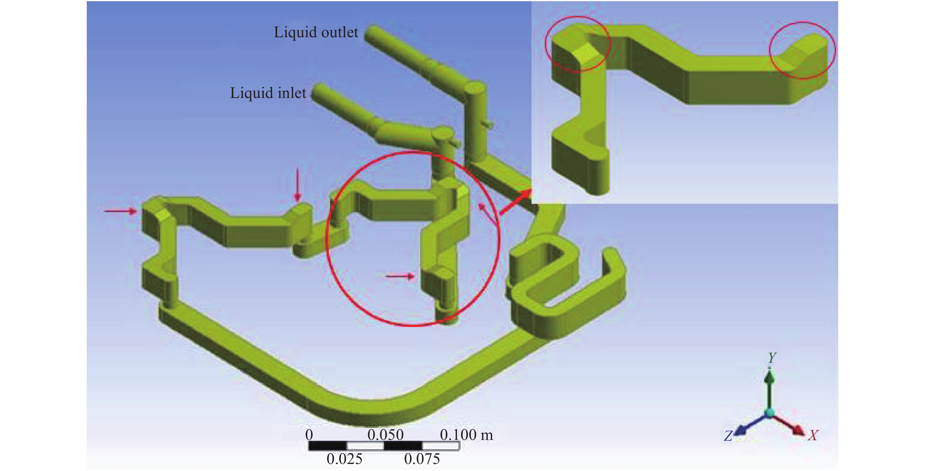
针对经典模型存在的不足,提出了一种非典型宏通道结构的优化模型。优化模型如图2所示,该模型增加了拐弯处侧壁曲度,同时将流通道整体加深2 mm,以增加流道内部的冷却液填充度。此外,对各模块的入水口处和热源3处的流体通道都进行了局部加深,使冷却液在进入模块时可以得到良好缓冲,优化了此处流道冷却液填充情况,提高了系统可靠性,同时也提高了热源1处和热源3处的散热效率,加深位置已在图2中箭头标出,右上角为Z02模块水路结构放大。

Figure 2. A typical macro-channel structure of optimized model
-
使用Fluent软件对两种模型进行流体分析和流体-固体耦合热传导分析[10-11],流体分析部分使用收敛性好,计算结果相对可靠的k-ε标准湍流模型,该模型中ε是各向同性小尺度涡旋的机械能转为热能的速率,ε和k是两个需要求解的未知量,其运算方程分别为:
式中:Gk为由于平均梯度引起的湍流动能k的产生项;Gb为浮力产生的湍流动能k的产生项;YM代表可压缩的湍流脉动扩张贡献;C1ε、C2ε和C3ε为经验常数;Sk和Sε为用户定义的源项[12]。对于热传导部分采用三维有热源的瞬态热传导模型,其表达式如下:
式中:ρ,c,k分别为介质的密度、比热容和导热系数;n代表介质的法线方向;h为介质表面和周围冷却液体的对流换热系数;qv为材料的热源强度。
式中:Ts为水冷板表面温度;Tf为冷却液温度。
公式(5)为初始条件,式中T0是初始温度。Fluent软件在求解以上3个导热方程时使用有限元分析法,将分析的对象划分成有限多个单元,根据能量守恒原理求解一定边界条件和初始条件下各个节点的热平衡方程得出各节点温度,从而求解出温度梯度变化[13-14]。
-
数值模拟计算中边界条件设置如下:
(1)整个系统共8个体热源,发热功率是80 W;
(2)水冷板材质为6061铝合金,出水口设置为压力出口;
(3)水冷机额定输出的冷却液使用去离子水,流速为15 L/min,水温恒定20 ℃;
(4)热源和各模块水冷板的接触面、流体与水流通道的接触面采用耦合边界条件,实现热传导;
(5)冷却系统装置外壁面定义为绝热面(忽略外界温度),不考虑自然对流和辐射换热。
-
图3是对经典模型进行流场分析后得到的流体轨迹图。经典模型中冷却液在流经Z01模块入水口处时产生了较大湍流旋涡,形成了湍流空洞,空洞情况已在图3中用红色圆圈标出,同样的情况在其他模块入水口处也有出现。这种湍流空洞不仅会使流道内部气泡增加,影响冷却液填充,降低冷却液流速,还会使流道内空泡效应增加,影响系统可靠性。
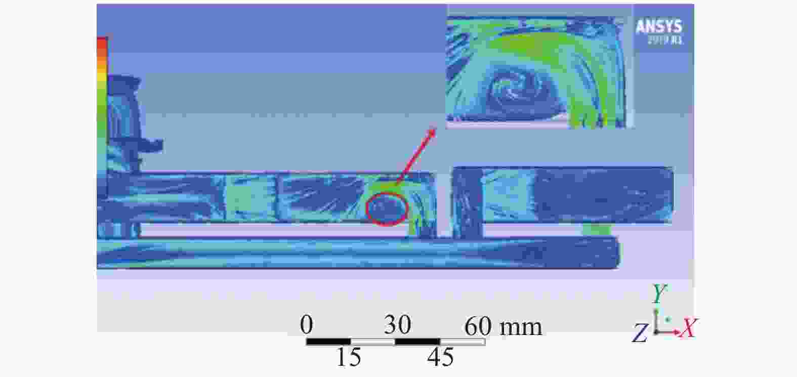
Figure 3. Fluid movement trajectory diagram in the channel of the classical model
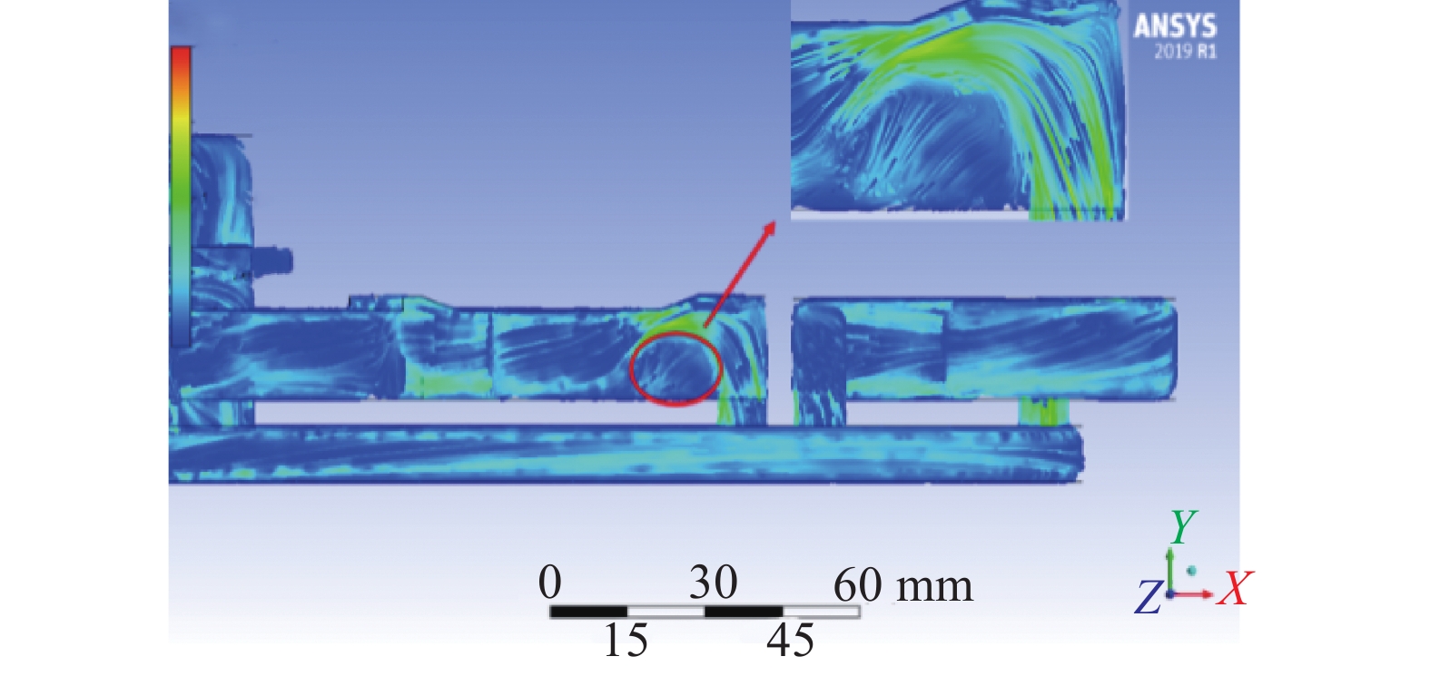
优化模型将各模块的入水口的管道进行了局部加深,加深后的管道可以使冷却液从下向上进入模块时得到缓冲。从图4中圆圈可以清晰看出,湍流空洞问题得到了明显改善,优化模型中的湍流空洞已经消失,冷却液在入水口处有良好的填充效果。
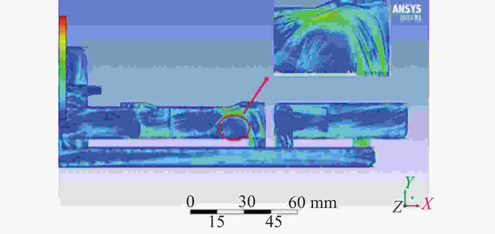
Figure 4. Fluid movement trajectory diagram in the channel of the optimized model
-
为了验证优化模型对水流通道中冷却液填充效果的影响,使用Fluent软件绘制出了两种模型相同参数条件下的上层冷却液的速度云图,绘制平面距离冷却液顶层2 mm。依据图1中的热源安装位置和冷却液的流向,在速度云图上对应热源正下方的位置设置了8个速度采集点,这些位置的冷却液流速直接关系到热源的散热效率。图5是经典模型上层冷却水流速图。
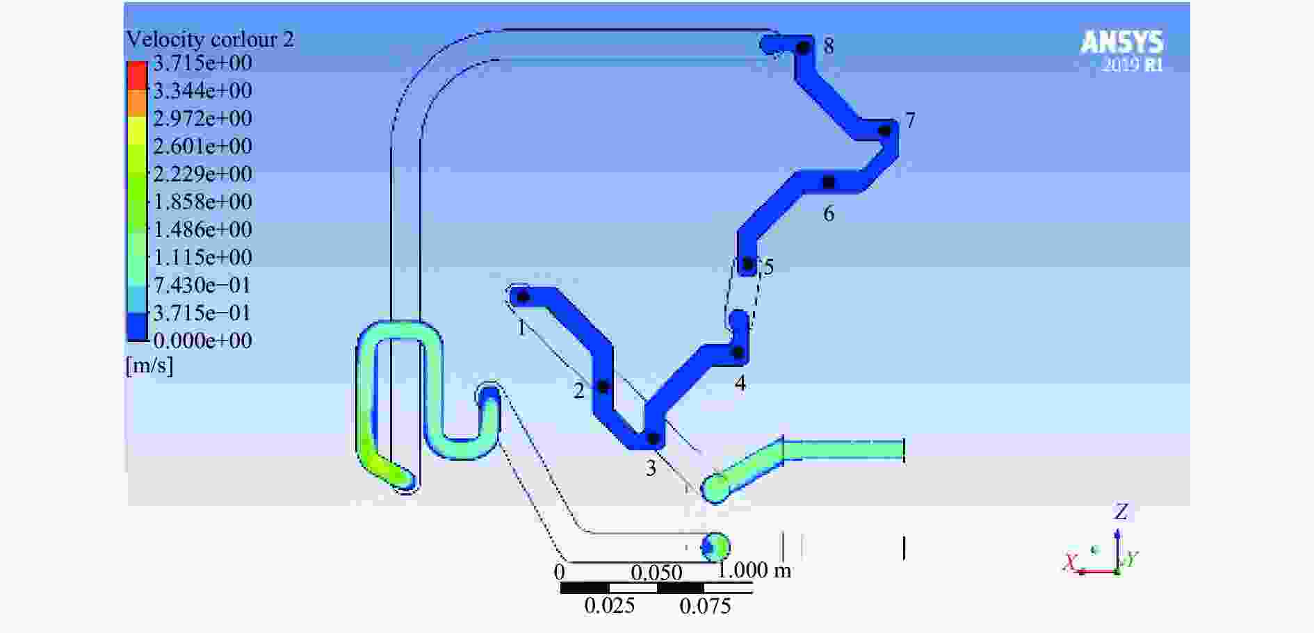
Figure 5. Upper cooling water flow rate diagram of the classical model
图中颜色深的区域冷却液流速较低,浅色区域流速较高。从图5中可知经典模型流道中各个热源下面冷却液流速较低。冷却液流速较低时,各个热源传导下来的热量无法及时被冷却液带走,直接影响到了热源处散热效率。这种情况在优化模型中得到了有效改善,优化模型上层冷却水流速情况如图6所示。
优化模型通道内冷却液填充效果更好,从图中可知上层冷却液的整体流速更高,同时,从采集点1、3、5和7处可以明显看出,模块入口处和热源3处流道加深区域冷却液流速提升明显,有利于解决局部热源散热效果较低的问题。

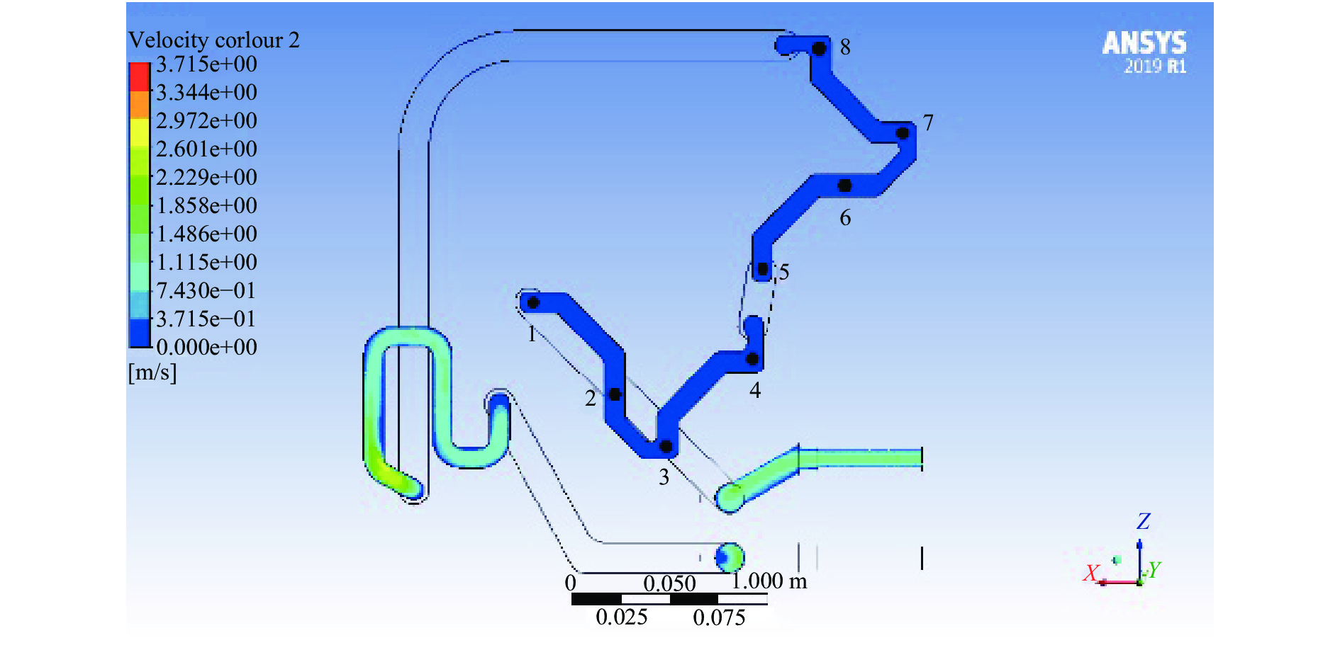
Figure 6. Upper cooling water flow rate diagram of the optimized model
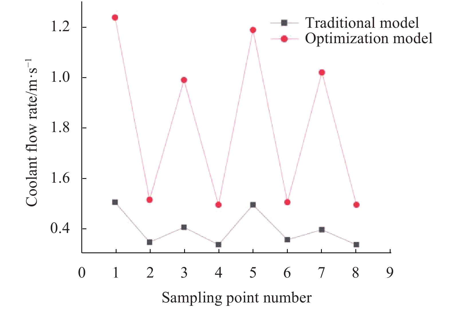
综上,仿真结果验证了优化模型可以明显提升水流通道中冷却液填充度,可以使局部冷却液获得更快的流速,有利于提高局部的散热效率。图7是采集点处采集到的数据绘制的速度曲线图。

Figure 7. Upper flow rate diagram of cooling water in the fluid channel
-
同样使用Fluent软件对两种模型工作时的激光器模块进行热分析,仿真结果如图8所示,其为经典模型工作时激光器模块热源温度云图。由于冷却液在流经热源1和热源3下的通道时填充度较低、流速低,导致经典模型出现热源1上温度分布不均匀和热源3上温度明显高于其他3个热源的情况,系统最高温度达到了31 ℃。这些情况不仅会影响bar条散热效率,导致输出功率降低,还会使输出光束出现“smile”效应。

Figure 8. Heat source temperature cloud diagram of the classical model
这些情况在优化模型工作时得到明显改善,由图9中标记的温度数据可知,热源1上温度分布较为均匀,最高温度下降了2 ℃左右;热源3上温度也有了明显降低,最高温度降到了29.6 ℃;此外,整个系统热源上的温度比经典模型降低了1.25 ℃左右,可知修改后的流体通道结构可有效提高模块的散热效率。
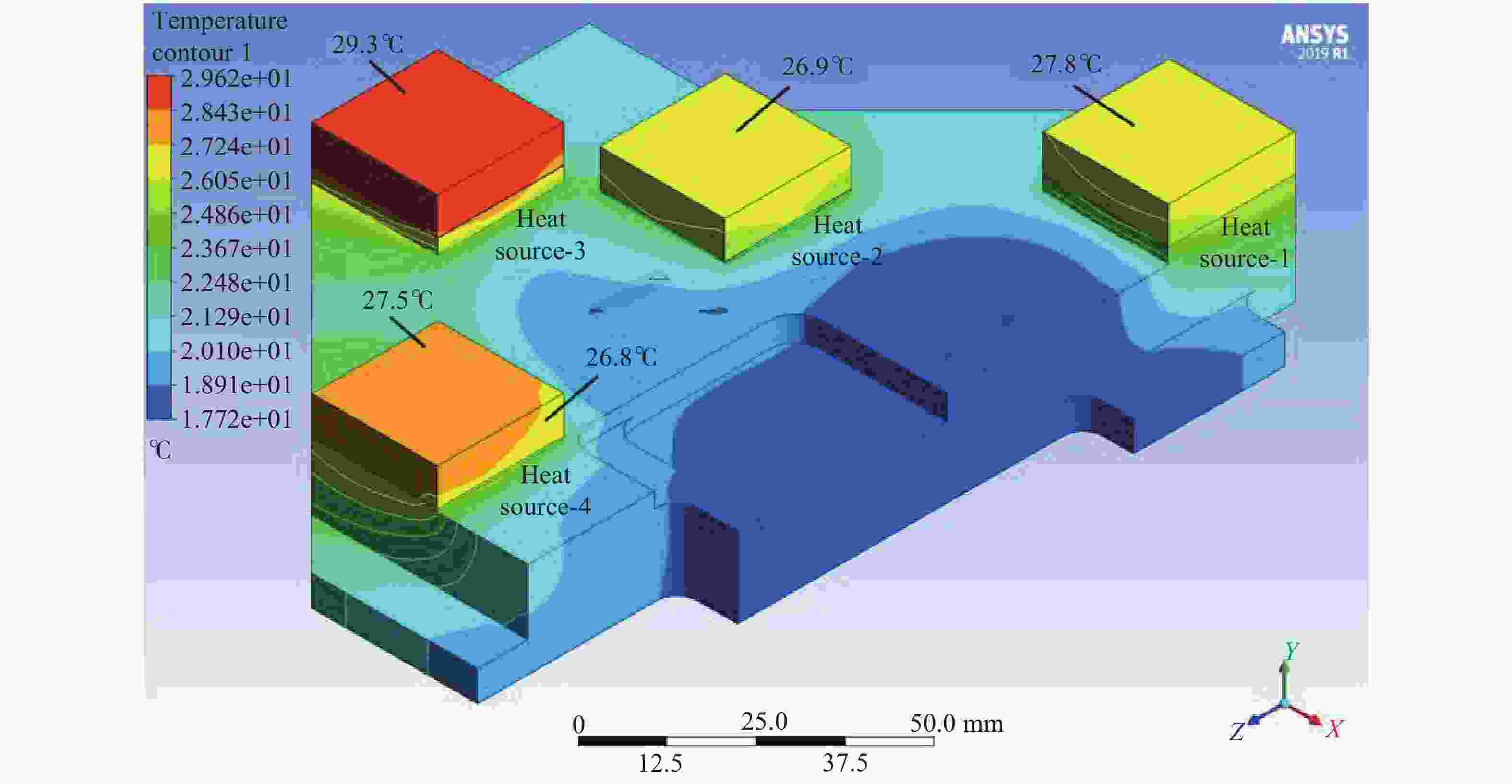
Figure 9. Heat source temperature cloud diagram of the optimized model
-
将两种结构的散热系统放置在相同的温度环境中,初始条件与数值模拟时保持一致。设定半导体激光器在额定功率下连续输出激光,8个热源的温度数据每2 s上传一次,记录工作2 min期间采集到的热源最高温度数据。根据仿真结果可知,整个系统中温度最高的热源是Z02模块的热源3,所以选取该热源上采集到的温度进行实验分析。图10是两种模型工作时Z02模块上热源3的温度变化图。
实验采集数据与仿真结果有差异的原因是仿真时不考虑自然对流散热和辐射换热,只考虑了冷却液对热源的散热效果。由数据可知,优化模型在22 s时到达温度最高点,比经典模型快4 s,同时优化模型工作时bar条到达额定工作温度(20~35 ℃)的时间也比经典模型快4 s,热源上温度平衡更快,使激光器具有更好的时效性,热源上最高温度比经典模型低1 ℃左右,温降与仿真结果基本一致。

Figure 10. Maximum temperature variation diagram of the heat source-3 in the Z02 module
-
文中在传统矩形腔流道结构模型的基础上,通过对流体通道内的冷却液进行流体分析的方式,提出了一种非典型宏通道结构的优化模型,并使用Fluent软件对模型进行了有限元分析,对比了两种模型的流体特性和温度场特性。仿真结果表明,相比于经典模型,优化模型中冷却液对流道的填充效果更好,流道内的上层冷却液流速更高,并且没有湍流空洞产生。此外,优化模型工作时,热源的温度分布更均匀,最高温度也比经典模型降低了1.25 ℃。最后进行了散热对比实验,采集到的热源温降数据与仿真结果基本一致,优化模型工作时,热源上温度平衡更快,到达温度最高点和进入额定工作温度时间比经典模型工作时快4 s,验证了优化后的设计方案明显提升了散热系统的散热性能和可靠性。
Design of atypical macro-channel water cooling system for semiconductor lasers
doi: 10.3788/IRLA20210037
- Received Date: 2021-05-15
- Rev Recd Date: 2021-06-25
- Available Online: 2022-01-06
- Publish Date: 2021-12-31
-
Key words:
- cooling system /
- semiconductor laser /
- Fluent /
- flow field analysis /
- temperature field analysis
Abstract: Comprehensive study on the cooling system of high-power semiconductor laser was carried out. Firstly, fluid analysis of the coolant in the channels of the cooling system was conducted, and the corresponding results showed that turbulent cavities were formed easily at the inlet and places with small comprehensive study on the cooling system of high-power semiconductor laser was carried out. Firstly, fluid analysis of the coolant in the channels of the cooling system was conducted, and the corresponding results showed that turbulent cavities were formed easily at the inlet and places with small curvatures. Turbulent cavities may not only cause the cavitation corrosion effect, but also cause the upper fluid channel near the heat source was not fully filled with coolant. In addition, turbulent cavities will also reduce the heat dissipation efficiency of the cooling system; Secondly, based on the traditional fluid channel structure, an optimized atypical macro-channel structure was proposed. The distribution of the heat dissipation model and the distribution of the laser module components were numerically simulated using Fluent that the finite element analysis software. The simulation results showed that no turbulence cavities were generated when the coolant flows in the fluid channel of the optimized model, and the upper layer of the fluid channel can be better filled with coolant. Simultaneously, the optimized model solved the problem of slow fluid velocity in the localized area of fluid channel of the classical model, not only improved the heat dissipation performance of the cooling system, but also improved the reliability of the cooling system. Additionally, according to the temperature field simulation results, the highest working temperature of the laser was decreased by 2 ℃ when applying the optimized cooling system. And the temperature on heat source-1 was more uniformly-distributed, while the temperature on heat source-3 was reduced by 1.25 ℃; Finally, the cooling system experiments were carried out and the results were well-matched with our simulation results.


 DownLoad: