Volume 50 Issue 12
Dec.  2021
Turn off MathJax
Article Contents

Li Lu, Xie Chenbo, Xing Kunming, Wang Bangxin, Zhao Ming, Cheng Liangliang. Optical-mechanical system design, installation and performance test of lidar with small-field and high-repetition frequency[J]. Infrared and Laser Engineering, 2021, 50(12): 20210046. doi: 10.3788/IRLA20210046
Citation: Li Lu, Xie Chenbo, Xing Kunming, Wang Bangxin, Zhao Ming, Cheng Liangliang. Optical-mechanical system design, installation and performance test of lidar with small-field and high-repetition frequency[J]. Infrared and Laser Engineering, 2021, 50(12): 20210046. doi: 10.3788/IRLA20210046

Optical-mechanical system design, installation and performance test of lidar with small-field and high-repetition frequency

doi: 10.3788/IRLA20210046
  • Received Date: 2021-01-24
  • Rev Recd Date: 2021-04-25
  • Available Online: 2022-01-06
  • Publish Date: 2021-12-31
  • In order to provide data correction and simulation for later development of space-borne lidar with high-repetition frequency, the lidar verification system with small-field of view and high-repetition frequency was designed and developed. Its opto-mechanical system was designed in detail, and the light path diagram of the transmitting, receiving and aft optical units was simulated by Zemax. The divergence angle of the outgoing beam was accurately calculated to be 0.106 mrad, and the new beam steering structure was designed to ensure the normal incidence into the beam expander. The field of view of receiving unit was 0.25 mrad with the iris diameter of 0.4 mm, the eccentricity of the diaphragm on the focal plane of the system should not exceed 29 μm, so the high-precision three-dimensional steering structure was selected to accurately position the iris. The design of the whole machine structure adopted the modular design concept, the different unit modules were installed in the different positions of the square frame. The structure was highly integrated, and the overall size was 390 mm×390 mm ×550 mm.The system transmitting unit was installed and calibrated, its divergence angle was detected to be 0.11 mrad. Compared with the simulation calculation, the relative error was 4.1%. The receiving and aft optic units were installed and calibrated, and the parallel light emitted by the collimator tube was used to enter the receiving telescope to obtain the precise position of the focal point of the system to complete the high-precision installation and calibration. Through the calibration experiment of the gain ratio of the system, the gain ration is 1.15. The detection experiments on the system show that the system can achieve aerosol detection distance of up to 22 km, and the depolarization ratio can reach 10 km at night. In the daytime, the detection distance can reach 10 km and the depolarization ratio can reach 6 km. Compared with the solar photometer, the relative error of optical thickness is 7.1%. The performance of the whole machine meets the design requirements, which lays a good foundation for the later experiments on the boat-borne.
  • [1] Di Huige, Hua Dengxin. Research status and progress of Lidar for atmosphere in China (Invited) [J]. Infrared and Laser Engineering, 2021, 50(3): 20210032. (in Chinese)
    [2] Li Lu, Xie Chenbo, Zhuang Peng, et al. Opto-mechanical system structure and research progress of space-borne lidar for cloud-aerosol [J]. Infrared and Laser Engineering, 2020, 49(8): 20190501. (in Chinese) doi:  10.3788/IRLA20190501
    [3] Lolli S, Vivone G, Lewis J R, et al. Overview of the new version 3 NASA Micro-Pulse Lidar Network (MPLNET) automatic precipitation detection algorithm [J]. Remote Sensing, 2019, 12(1): 71. doi:  10.3390/rs12010071
    [4] Lolli S, D’ Adderio Leo, Campbell J, et al. Vertically resolved precipitation intensity retrieved through a synergy between the ground-based NASA MPLNET lidar network measurements, surface disdrometer datasets and an analytical model solution [J]. Remote Sensing, 2018, 10(7): 1102. doi:  10.3390/rs10071102
    [5] Lewis J R, Campbell J R, Welton E J, et al. Overview of MPLNET version 3 cloud detection [J]. Journal of Atmospheric and Oceanic Technology, 2016, 33(10): 2113-2134. doi:  10.1175/JTECH-D-15-0190.1
    [6] Mcqill M, Hlavka D, Hart W, et al. Cloud physics lidar: Instrument description and initial measurement results [J]. Applied Optics, 2002, 41(18): 3725-3734. doi:  10.1364/AO.41.003725
    [7] Storm M, Stevenson G, Hovis F, et al. Lidar and laser technology for NASA’S Cloud-Aerosol Transport System (CATS) payload on the international space station (JEM-EF) [J]. EPJ Web of Conferences, 2016, 119: 04002.
    [8] Yorks J E, Mcgill M J, Nowottnick E P. Near real time vertical profiles of clouds and aerosols from the Cloud-Aerosol Transport System (CATS) on the international space station[C]//AGU Fall Meeting, 2015.
    [9] Yorks J E, Mcgill M J, Scott V S, et al. The airborne cloud–aerosol transport system: Overview and description of the instrument and retrieval algorithms [J]. Journal of Atmospheric & Oceanic Technology, 2014, 31(11): 2482-2497.
    [10] Chen Shasha, Xu Qingshan, Xu Chidong, et al. Calculation of whole atmospheric aerosol optical depth based on micro-pulse lidar [J]. Acta Optica Sinica, 2017, 37(7): 0701002. (in Chinese) doi:  10.3788/AOS201737.0701002
    [11] Zhu Cunxiong, Cao Nianwen, Yang Fengkai, et al. Micro pulse lidar observations of aerosols in Nanjing [J]. Laser & Optoelectronics Progress, 2015, 52(5): 050101. (in Chinese)
    [12] Li Hui, Wang Zhangjun, Wang Haoyue, et al. Combined observation of aerosol vertical structure using micro-pulse lidar and compact optical backscatter aerosol detector [J]. Laser & Optoelectronics Progress, 2019, 56(13): 132801. (in Chinese)
    [13] Luo Jing, Liu Dong, Huang Zihao, et al. Polarization properties of receiving telescopes in atmospheric remote sensing polarization lidar [J]. Applied Optics, 2017, 56(24): 6837-6845. doi:  10.1364/AO.56.006837
  • 加载中
通讯作者: 陈斌, bchen63@163.com
  • 1. 

    沈阳化工大学材料科学与工程学院 沈阳 110142

  1. 本站搜索
  2. 百度学术搜索
  3. 万方数据库搜索
  4. CNKI搜索

Figures(17)  / Tables(2)

Article Metrics

Article views(420) PDF downloads(79) Cited by()

Related
Proportional views

Optical-mechanical system design, installation and performance test of lidar with small-field and high-repetition frequency

doi: 10.3788/IRLA20210046
  • 1. Key Laboratory of Atmospheric Optics, Anhui Institute of Optics and Fine Mechanics, Hefei Institutes of Physical Science, Chinese Academy of Sciences, Hefei 230031, China
  • 2. Science Island Branch of Graduate School, University of Science and Technology of China, Hefei 230026, China
  • 3. Advanced Laser Technology Laboratory of Anhui Province, Hefei 230037, China
  • 4. Faculty of Mechanical and Automotive Engineer, West Anhui University, Lu’an 237012, China

Abstract: In order to provide data correction and simulation for later development of space-borne lidar with high-repetition frequency, the lidar verification system with small-field of view and high-repetition frequency was designed and developed. Its opto-mechanical system was designed in detail, and the light path diagram of the transmitting, receiving and aft optical units was simulated by Zemax. The divergence angle of the outgoing beam was accurately calculated to be 0.106 mrad, and the new beam steering structure was designed to ensure the normal incidence into the beam expander. The field of view of receiving unit was 0.25 mrad with the iris diameter of 0.4 mm, the eccentricity of the diaphragm on the focal plane of the system should not exceed 29 μm, so the high-precision three-dimensional steering structure was selected to accurately position the iris. The design of the whole machine structure adopted the modular design concept, the different unit modules were installed in the different positions of the square frame. The structure was highly integrated, and the overall size was 390 mm×390 mm ×550 mm.The system transmitting unit was installed and calibrated, its divergence angle was detected to be 0.11 mrad. Compared with the simulation calculation, the relative error was 4.1%. The receiving and aft optic units were installed and calibrated, and the parallel light emitted by the collimator tube was used to enter the receiving telescope to obtain the precise position of the focal point of the system to complete the high-precision installation and calibration. Through the calibration experiment of the gain ratio of the system, the gain ration is 1.15. The detection experiments on the system show that the system can achieve aerosol detection distance of up to 22 km, and the depolarization ratio can reach 10 km at night. In the daytime, the detection distance can reach 10 km and the depolarization ratio can reach 6 km. Compared with the solar photometer, the relative error of optical thickness is 7.1%. The performance of the whole machine meets the design requirements, which lays a good foundation for the later experiments on the boat-borne.

  • 激光雷达作为一种主动遥感技术,广泛应用在探测大气气溶胶和云的时空分布特性中。随着激光技术和探测技术的不断发展,特别是小型化激光器的技术不断成熟,使得激光雷达的整机体积及成本得到了有效的控制[1]。根据激光光源能量和重复频率分类可知,激光雷达激光光源主要分为低重频高能量和高重频低能量两大类。与采用低重频高能量激光器的激光雷达相比,高重频低能量激光器的激光雷达具有较小的整机结构尺寸及质量;相同性能指标下,成本低;高的重复频率获得单位时间的脉冲数目多,可提高激光平均发射功率,弥补其信噪比不足。采集系统采用光子技术的探测模式,对白天背景信号进行有效的抑制提出更高要求[2]

    高重频低能量激光雷达中,最典型的微脉冲激光雷达(Micro-Pulse Lidar,MPL),脉冲能量在μJ数量级,重复频率大于等于kHz,在国内外得到了广泛的研究及应用。就国外而言,最初的实验样机是由美国NASA-Goddard Space Flight Center(GSFC)研制,用于1993年星载激光雷达探测西南太平洋上空气溶胶和云的垂直分布特性。2000年,由美国国家航空航天组织建立的全球微脉冲激光雷达网(Micro-Pulse Lidar Network,MPLNET)用于大气气溶胶和云的全球范围内的全天时、全自动观测[3-4]。由Sigma Space公司生产的MiniMPL具有高的集成度,小的体积,更便捷,性价比高,从探测结果可知,白天探测距离约10 km,背景噪声抑制在0.7 MHz以内;晚上探测距离约20 km,背景信号抑制在8e-04 MHz以内[5]。由美国NASA研制的云物理激光雷达(Cloud Physics Lidar,CPL)[6],重复频率为5 kHz,脉冲能量为μJ数量级,搭载在飞行高度约为20 km的ER-2的飞机上,探测的大气气溶胶和云的垂直数据用于地球激光测高系统(Geo-science laser Altimeter System,GLAS)和正交偏振云-气溶胶激光雷达(Cloud-Aerosol Lidar and Infrared Pathfinder Satellite Observations,GALIPSO)数据验证及模拟研究。2015年,美国NASA研制出云-气溶胶传输系统(Cloud-Aerosol Transport System,CATS)[7-8],设计了两套发射系统,用于实现不同探测模式,其中一个激光器由CPL设备中继承发展过来,重复频率为5 kHz,能量为2 mJ;另一个激光器采用种子注入脉冲激光器,由机载云-气溶胶传输系统[9]设备继承发展过来,重复频率为4 kHz,能量为2 mJ;轨道高度为405 km,完成了为期33个月的大气探测任务。在国内,中国科学院安徽光学精密机械研究所、西安理工大学、中国海洋大学、苏州大学以及山东省科学院海洋仪器仪表研究所等科研单位相继研究出MPL,用于大气气溶胶和云的垂直、水平以及三维扫描的探测研究,从探测结果可知,白天探测距离为3~5 km,晚上探测距离为10~15 km;中国海洋大学在原有的MPL设备基础上改进研制出机载MPL,飞行高度只有3 km,完成3 km以下的大气气溶胶和云的垂直分布探测任务[10-12]

    文中重点研制一套小型化高重频激光雷达,具有集成度高、体积小、质量轻、视场小等特点,探测指标为白天可达到8 km,晚上可达到20 km,探测数据为后期研制星载高重频激光雷达原理样机数据反演提供校正与仿真。

  • 小视场高重频激光雷达系统结构示意图如图1所示,该系统光学单元部分主要分为发射单元系统、接收单元系统和后继单元系统。从光路上看,首先由激光器出射激光,通过光束转折反射镜将激光正入射到扩束器中,再从扩束器出射到反射镜上,通过电动调整架调节反射镜姿态将激光反射到大气中,完成激光的发射。由大气返回的回波光信号通过望远镜接收,通过小孔光阑和目镜将回波光信号变成平行光,经后继光路将回波光信号分成532垂直和平行两探测通道。探测器将光信号转换成电信号,经过数据采集、滤波技术及数据分级技术将云和气溶胶垂直分布信息存储起来。在计算&控制平台中,主要控制对象有控制激光器电源及触发、控制扫描电机上的反射镜偏转等。小视场高重频激光雷达系统参数如表1所示。

    Figure 1.  Schematic diagram of lidar system structure with small-field of view and high-repetition frequency

    ItemParameters
    LaserWavelength/nm532.18
    Repetition rate/kHz3
    Output divergence2 (full)
    Output beam energy1
    Beam expansion20X
    TelescopeDiameter/mm125
    Field of view0.28(full)
    Focal length/mm1430
    Diffuse spots/mm<0.045
    Wavefront difference<1/4λλ=632.8 nm)
    Focal length of ocular/mm50
    Reflector(532 nm)R:99%
    Filter bandwidth/nm0.3
    Extinction ratio of polarizing prism3000:1
    DetectorPMT
    Capture cardPhoton

    Table 1.  System parameters of lidar with small-field and high-repetition frequency

  • 设计发射单元发散角要求为0.1 mrad,选用某公司提供的20倍扩束器来压缩激光器出射光束发散角。利用Zemax软件进行模拟仿真,采用光束出射口径为1 mm,发散角为2 mrad来模拟激光器出射光源。通过折转反射镜将激光光束正入射到扩束器中,经过扩束后两折转反射镜反射到大气中,所设计的发射单元模块光路图如图2所示。通过计算获得发射单元发散角为0.106 mrad,与设计要求相差不到10%。

    Figure 2.  Light path diagram of optical-mechanical system of the transmitting unit

    在实际安装过程中装校误差不可避免,使得激光光束成一定的角度入射到扩束器中,从而影响扩束效果。为了研究激光光束入射到扩束器的角度对扩束效果的影响,通过改变扩束器倾斜角度来模拟入射角度对扩束的影响。图3为不同入射角对扩束后的光束发散角影响。

    Figure 3.  Relation curve between incident angle and divergence angle after beam expansion

    图3可知,随着入射角的不断增大,其扩束后的发散角近似线性增加,因此采用折转镜调整激光光束方向进行补偿。一般采用三维调整架调节折转镜的位姿来进行角度补偿,但这种调整架只适合在实验室中进行,因为其结构不稳定的。设计新型的光束转向结构,可以实现垂直于光轴方向的平动及改变光轴方向的转动,其中平动可实现激光光轴落到反射镜的旋转中心,再通过转动可改变光轴方向来实现角度补偿。如图4所示,为所设计发射单元的光机结构图。

    Figure 4.  Optical-mechanical structure of transmitting unit

  • 望远镜光学系统设计时,确定中心遮拦比为0.272,由于缩比样机总体尺寸的严格限制,结合控制主次镜间距为200 mm。望远镜由某公司提供,光学参数如表2所示。

    Radius of curvature/mmDistance to the next side/mmRadius/mmQuadric coefficient
    −516−20068 0
    −141.536321.82 176.288

    Table 2.  Optical parameters of telescope of lidar with miniaturization and high-repetition frequency

    通常采用视场角乘以望远镜焦距来计算出小孔光阑孔径,所设计的接收视场角为0.28 mrad,望远镜焦距为1430 mm,计算出的小孔光阑孔径约为0.4 mm。如图5所示,为所设计的接收与后继单元光路图。

    Figure 5.  Light path diagram of optical-mechanical system of the receiving and aft-optical unit

    利用Zemax软件对接收视场角进行仿真,文中以平行光入射角0.14 mrad模拟接收视场角(半角)进行仿真模拟,获得探测器靶面的光斑,如图6所示。

    Figure 6.  Light spot on the target surface of the detector under the field of view of 0.14 mrad (half angle)

    图6所示,在0.14 mrad (半角)视场下,探测器靶面上的光斑偏心为1.398 mm,光斑半径为1.906 mm(无光阑),如图6(a)所示,完全被8 mm探测器靶面所探测;而在0.4 mm孔径光阑下,探测器靶面光斑不完整,如图6(b)所示,说明在0.4 mm孔径光阑下实际接收视场角小于0.28 mrad,原因没有考虑到望远镜焦点处弥散斑直径所导致。

    为了进一步研究在0.28 mrad视场下,0.4 mm孔径光阑下挡光的原因,利用Zemax软件对望远镜进行仿真模拟,获得望远镜在0.14 mrad(半角)视场下望远镜系统弥散斑,如图7(a)所示。

    Figure 7.  Diffuse spots (a) and energy concentration (b) of telescope system under the field of view of 0.14 mrad (half angle)

    图7(a)可知,在0.14 mrad (半角)视场下望远镜系统弥散斑偏心0.199 mm,以主光线偏心位置为坐标原点,获得望远镜系统能量集中度,如图7(b)所示。根据光斑直径的测量原理,圈入能量分数为86.5%的圆半径作为弥散斑半径。由图7(b)可得,圈入能量分数为86.5%时,在视场0.14 mrad (半角)下的半径为20.9 μm,因此小孔光阑孔径为0.4398 mm才能满足视场0.28 mrad的探测功能,而实际的小孔光阑孔径只有0.4 mm,故利用Zemax软件仿真计算出不同视场下望远镜系统弥散斑偏心及半径,如图8所示。

    Figure 8.  Eccentricity(a) and radius(b) of diffuse spot of the telescope system under different fields of view

    图8可以看出,望远镜的视场角与弥散斑偏心和半径近似成线性关系,可线性拟合推导出其关系式为:

    式中:θr为接收视场角(全角),单位为mrad;e为弥散斑偏心值,mm;${r_1}$为弥散斑半径,μm。当小孔光阑孔径d为0.4 mm时,由公式(1)计算出望远镜的视场角为0.25 mrad,较理想视场角0.28 mrad减小10.7%。

    根据工程经验,一般设计接收视场角是发射光束发散角的两三倍,因此文中所设计的接收视场角不得小于0.212 mrad。通过公式(1)计算出所需小孔光阑孔径为0.34188 mm,故0.4 mm孔径的小孔光阑在焦平面处偏心不得超过29 μm,因此设计高精度的三维调整架来精确定位小孔光阑的位置,整个接收与后继单元光机结构如图9所示。

    Figure 9.  Optical-mechanical structure of the receiving and aft optical unit
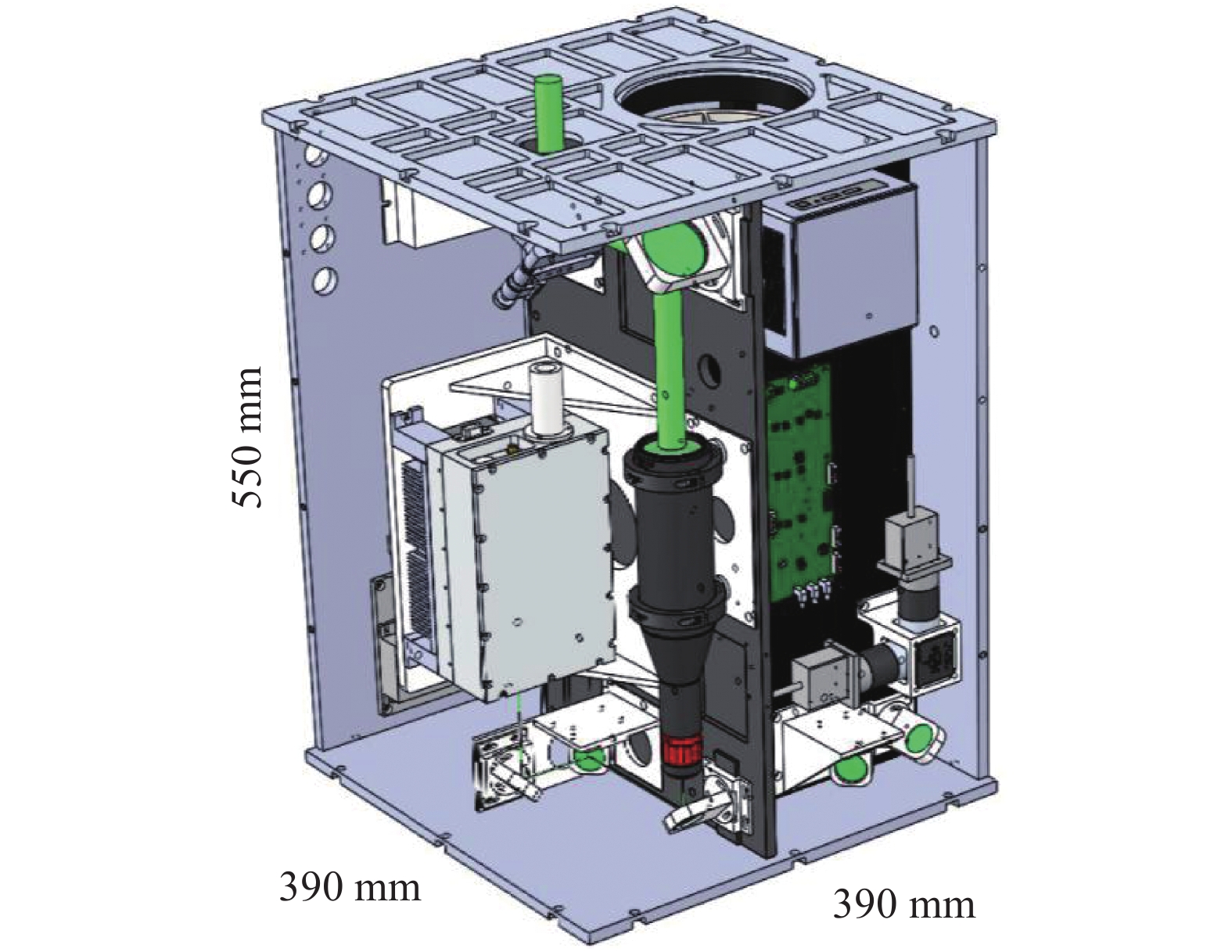
  • 图10所示,总体结构方案以方形框架为基准,首先将望远镜固定在方形框架所在的基板上,将小孔光阑、目镜以及光束转向反射镜固定在基板的另一侧;然后将发射单元模块、后继单元模块以及电控单元模块分别固定在方形框架的三个侧面,可有效地将电学部分与后继单元隔离开来,避免相互干扰。数据采集单元与数据存储与发送模块与后继单元一起固定在一个工作平板上。在发射单元装调过程中,将发射单元模块固定在一个工作平板上,并把光路装调好,然后将整个发射单元系统装备到方形框架中,只要通过程序自动控制调整反射镜达到与接收光轴平行的效果可有利于发射单元的装调,大大缩短整机的装调时间,互换性好。

    Figure 10.  Lidar effective payload with small-field of view and high-repetition frequency

  • 对发射单元光机结构进行装调,如图11(a)所示,为发射单元的装调实验实物图。在该实验中,温度环境控制在22 ℃,首先将激光器及调节好的扩束器固定在工作平板上,然后通过激光器出光,通过光束转向结构调节激光的光束方向,高准直入射到扩束器中,并通过两反射镜反射出去。

    为了检测扩束后的激光发散角,检测光路图如图11(b)所示,利用CCD相机对挡光板上的光斑进行检测,选取圈入能量为86.5%的光斑直径。检测出在出光口0.5 m处的光斑直径平均值为21.05 mm;在20 m处的光斑直径平均值为21.27 mm,计算出扩束后的激光发散角为0.113 mrad (全角),与仿真计算0.106 mrad相比,相对误差为6.195%,这主要由激光器出射的实际发散角和扩束器的性能共同决定。

    Figure 11.  Adjustment of optical-mechanical structure (a) and detection optical path of divergence angle (b) in transmitting unit

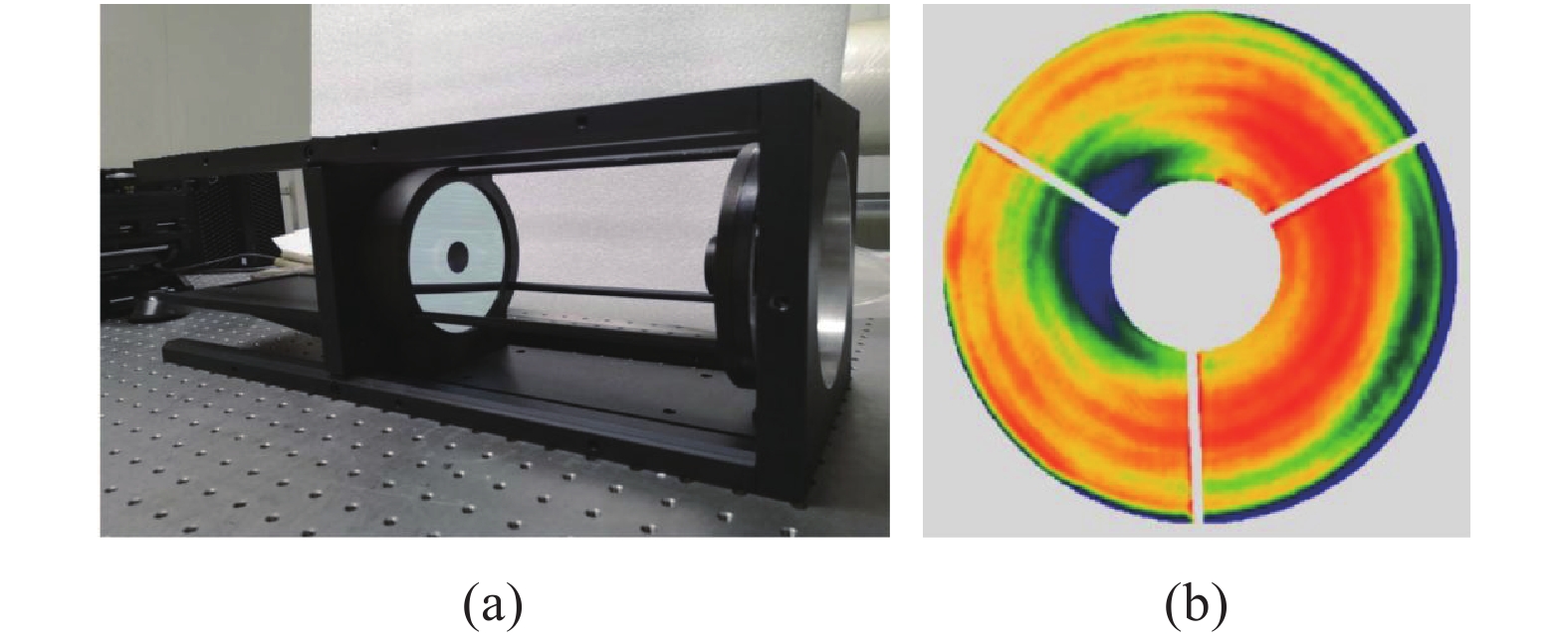
  • 为获得望远镜的系统波向差(图12(a)),利用干涉仪对望远镜进行实验测试,获得系统波前差(图12(b)),系统波前差RMS为0.0986$\lambda $$\lambda $=632.8 nm),小于0.25$\lambda $$\lambda $=632.8 nm),符合设计要求。

    Figure 12.  Detection (a) and results (b) of the wave aberration of telescope system

    对接收与后继单元光机结构进行装调实验,如图13所示,为接收与后继单元的装调实物图。在该实验中,温度环境控制在22 ℃,首先将接收与后继单元系统结构放置在高精度三维调节的工作平台上,将光源打开,通过调节接收与后继单元系统结构的位置,使得平行光管出射的平行光正入射到系统结构中,并通过高精度的三维调节结构调节小孔光阑的位置,找到望远镜系统焦点的位置,调节目镜,将光束变成平行光,再通过光束转向镜将平行光正入射到窄带虑光片,进入偏振棱镜,分成两探测通道。利用CCD相机检测出进入探测器靶面光斑直径平均值为3.86 mm,与模拟计算获得几何半径为3.698 mm,相对误差为4.196%,且完全可以被直径为8 mm的探测器探测。

    Figure 13.  Adjustment of optical-mechanical structure of receiving and aft optical units

  • 测试之前,利用能量计对激光雷达的出口激光能量进行检测,检测能量为0.883 mJ。选择一个晴朗的夜晚进行系统标定。系统在2020年10月11日晚23:13探测的回波信号如图14所示,垂直通道(S)回波信号背景信号约为0.06281 MHz,最大幅值为12.126 MHz;平行通道(P)回波信号背景信号约为0.00425 MHz,最大幅值为87.02 MHz。S通道回波信号回波强度远小于P通道,而S通道回波信号背景信号是P通道的14.77倍,从而使得S通道探测高度远小于P通道。两通道的比值作为不考虑增益比$k(\lambda )$的大气退偏比廓线,如图15所示,2.5 km以后退偏比廓线没有明显的变化,近似一条直线,说明2.5 km以上是平滑的,但是随着高度的不断增加,S通道回波信号强度弱,信噪比差,出现毛刺,并越来越严重,但不影响退偏比的整体变化趋势。取4~6 km作为标定高度,计算出平均值为0.0242。

    Figure 14.  Original signal detected at 23:13 on October 11, 2020

    Figure 15.  Ratio of echo signal of S channel and P channel

    文中采用大气分子法[13]对系统增益比进行标定,即在无气溶胶区域内,大气中只有空气分子,其退偏振比为0.0279,可计算出系统增益比$k(\lambda )$为1.15。

  • 为了验证激光雷达系统的探测性能,选择晴天无云的天气条件下,分别在夜晚和白天进行探测,如图1617所示,分别为2020年10月12日00:24和11月04日12:00探测反演的消光系数及退偏振比廓线。

    Figure 16.  Profile of extinction coefficient (a) and depolarization ratio (b) detected at 12:00 on November detected at 00:24 on October 12, 2020

    Figure 17.  Profile of extinction coefficient (a) and depolarization ratio (b) detected at 12:00 on November 04, 2020

    图16可知,在边界层1.49 km以内,气溶胶的消光系数在0.1~0.25 km−1之间变化,对应的退偏振比在0.075~0.175变化;在1.49~2.3 km范围内,出现气溶胶层,消光系数在0.01~0.025 km−1之间变化,对应的退偏振比在0.05~0.08之间变化。在2.3 km以上,气溶胶的消光系数小于分子消光,在1421 km,气溶胶消光廓线明显地拱起,说明该区域有气溶胶,且含量很少,对应的退偏振比在0.028左右变化,近似空气分子的退偏振比,但随着高度增加,退偏振比毛刺越多,这是由于S探测通道信噪比差所致。由消光垂直廓线可知,可实现22 km的探测高度,计算出的光学厚度为0.159 5;退偏振比可实现10 km探测高度,满足夜晚的探测要求。

    图17可知,在边界层1.38 km以内,气溶胶的消光系数在0.012~0.14 km−1之间变化,对应的退偏振比在0.06~0.13之间变化;在1.61~4.1 km的范围内,出现气溶胶层,消光系数在0.0055~0.031 km之间变化,对应的退偏振比在0.031~0.125之间变化。在4.1 km以上,气溶胶的消光系数小于分子消光,对应的退偏振比在0.028左右变化,近似空气分子的退偏振比,但随着高度增加,退偏振比毛刺越多,这是由于S探测通道信噪比差所致。由消光垂直廓线可知,可实现10 km的探测高度,计算出光学厚度为0.1973,此时利用太阳光度计测出的光学厚度为0.2124,相对误差为7.109%;退偏振比可实现6 km的探测高度,满足白天的探测要求。

  • 研制出一套小视场高重频低能量激光雷达验证系统,高度集成在尺寸在390 mm×390 mm×550 mm以内,为后期研制星载高重频激光雷达原理样机数据反演提供校正与仿真。

    在整机光学结构设计中,通过Zemax软件设计光机系统的光路图,通过计算得出:发射单元发散角为0.106 mrad,设计新型光束转向结构满足正入射;在0.4 mm光阑下,接收视场角为0.25 mad,在系统焦平面上的小孔光阑偏心不得超过29 μm,保证接收视场不低于0.212 mrad,设计高精度三维调整架来精确定位小孔光阑的位置。对发射光机结构进行高精度的装校,检测计算出发散角为0.113 mrad,与仿真计算相比,相对误差为6.195%,主要由激光器出射的实际发散角和扩束器性能共同决定的。在接收和后继光机单元中,首先利用干涉仪检测望远镜的系统波前差RMS为0.0986$\lambda $$\lambda $=632.8 nm),满足小于0.25$\lambda $$\lambda $=632.8 nm)的设计要求。然后利用平行光管获得平行光准直入射到接收望远镜中获得系统的焦点位置,通过高精度三维调整结构确定0.4 mm光阑准确位置,依次装校对应的目镜、反射镜、滤光片、偏振棱镜以及探测器。检测出进入探测器靶面光斑直径平均值为3.860 mm,与模拟计算获得几何半径为3.698 mm,相对误差为4.196%,且完全可以被直径为8 mm的探测器探测。

    在整机安装完成后,出射激光能量为0.883 mJ。采用大气分子法对系统增益比进行标定,获得系统增益比为1.15。选择晴朗无云的天气条件下,分别在白天和夜晚进行性能测试,探测结果显示:夜晚气溶胶探测距离可达22 km,退偏振比可达10 km;白天探测距离可达10 km,退偏振比可达6 km,计算出的光学厚度与太阳光度计进行比较,相对误差为7.109%;整机性能满足设计要求。

Reference (13)

Catalog

    /

    DownLoad:  Full-Size Img  PowerPoint
    Return
    Return