


-
可见-近红外连续变焦光学系统兼具大视场搜索与小视场详查功能,还可通过工作谱段的切换实现光学透雾,通过调焦功能实现对不同温度环境的适应,在诸多场景获得广泛应用,但对诸如航空摄影、侦察跟踪等特殊应用场景,反复调焦可能导致目标丢失,影响功能实现,这就要求光学系统具备无热化功能,保证光学系统在不同温度环境下无需调焦均可清晰成像[1-4]。
另外,对于连续变焦光学系统,在焦距连续变化过程中动组间相对位置发生变化,成像系统放大倍率、像差特性等均随之改变,各焦距位置的热差和色差也发生变化,而且光学系统的大相对孔径化导致系统焦深范围变窄,也对消热设计提出了更大的挑战。
针对以上问题,文中结合变焦系统像差模型和变焦系统的消色差、热差模型,阐述了一种宽波段无热化连续变焦系统的设计方法,对类似光学系统的设计具有参考作用。
-
变焦系统由定组和动组两部分组成,并将动组的组合称为变焦核,此时变焦光学系统的波像差函数
$ W\left(\mathop H\limits^{\rightharpoonup},\mathop {\rho }\limits^{\rightharpoonup},\gamma \right) $ 可表示为:式中:
$ {W}_{P}\left(\mathop H\limits^{\rightharpoonup},\mathop {\rho }\limits^{\rightharpoonup}\right) $ 为定组的波像差函数;$ {W}_{K}\left(\mathop H\limits^{\rightharpoonup},\mathop {\rho }\limits^{\rightharpoonup}\right) $ 为动组内的波像差函数;$ {W}_{K}\left(\mathop H\limits^{\rightharpoonup},\mathop {\rho }\limits^{\rightharpoonup},\gamma \right) $ 为由动组移动产生的波像差函数,或称为变焦核波像差函数;$ \mathop H\limits^{\rightharpoonup} $ 为归一化视场矢量;$ \mathop {\rho }\limits^{\rightharpoonup} $ 为归一化光瞳矢量;$ \gamma $ 为归一化光焦度变化量。此时,变焦系统的像差函数分解为独立的三类像差,相应设计任务转变为:设计相应的变焦核,实现要求的变倍比,并控制
$ {W}_{K}\left(\mathop H\limits^{\rightharpoonup},\mathop {\rho }\limits^{\rightharpoonup},\gamma \right) $ ;设计相应的定组,满足其他设计要求,并控制$ {W}_{P}\left(\mathop H\limits^{\rightharpoonup},\mathop {\rho }\limits^{\rightharpoonup}\right) $ 和$ {W}_{K}\left(\mathop H\limits^{\rightharpoonup},\mathop {\rho }\limits^{\rightharpoonup}\right) $ 。通过将变焦系统的像差分为依赖与不依赖焦距变化的三类像差,可有效简化整个变焦光学系统的设计过程[5-6]。进一步的,可对变焦核初级波像差做三阶多项式展开,则有:
式中:前两项分别为变焦核的倍率色差和轴向色差;后五项分别为球差、彗差、像散、场曲和畸变。此时,
$ {W}_{K}\left(\mathop H\limits^{\rightharpoonup},\mathop {\rho }\limits^{\rightharpoonup},\gamma \right) $ 转化为归化光焦度的多项式函数。据此,下面采用薄透镜理论简要讨论变焦系统中的消色差和消热差模型。对于其他类型的变焦系统,可通过类似的方法进行分析设计。
-
对于电视观测类变焦系统,为了避免产生色离焦,设计阶段需特别关注轴向色差
$ {W}_{020}^{}\left(\mathop {\rho }\limits^{\rightharpoonup} \cdot \mathop {\rho }\limits^{\rightharpoonup}\right) $ 。而对于 如图1所示的两动组型变焦系统,沿光路通常设置有前固定组、变倍组、补偿组和后固定组;各组元需同时满足光焦度方程和焦面恒定方程,即
Figure 1. Schematic diagram of typical two part zoom lens system
其中,设组合系统的焦距为
$ {f}^{'} $ ;前固定镜组焦距为$ {f}_{1}^{'} $ ;变倍组焦距为$ {f}_{2}^{'} $ ,放大倍率为m2;补偿组焦距为$ {f}_{3}^{'} $ ,放大倍率为m3。另外,当光学系统工作谱段较宽,由材料导致的色差不可忽略,各组元还需满足消色差条件,将公式(1)对折射率作全微分,可得变焦系统的轴向色差:
将公式(1)代入公式(3),并设后固定组焦距为
$ {f}_{4}^{'} $ ,放大倍率为m4,各镜组的焦像距分别为$ {{x}}_{2}^{'}{\text{、}}{{x}}_{3}^{'}{\text{和}}{{x}}_{4}^{'} $ ,考虑各镜组放大率$ {m}_{2}=-\dfrac{{{x}}_{2}^{'}}{{f}_{2}^{'}} $ ,$ {m}_{3}=-\dfrac{{{x}}_{3}^{'}}{{f}_{3}^{'}}{\text{和}}{m}_{4}=-\dfrac{{{x}}_{4}^{'}}{{f}_{4}^{'}} $ ,并采用二级近似,可得:前四项为定组和动组内的轴向色差,后三项为变焦核的轴向色差。若定义
$ \dfrac{\Delta {f}^{'}}{{f}^{'}} $ 为镜组色散能力,则变焦系统的轴向色散主要受各镜组的色散能力、前固定组的轴向色散和变倍补偿组的放大倍率限制。对单个薄透镜而言,$ \dfrac{{\Delta f}_{c}^{'}}{{f}^{'}} $ 在数值上等于阿贝数的倒数,为归化色差系数[7-9]。此时,对于光学系统中的短焦位置,变倍补偿组的放大倍率m2和m3通常均小于1,组元间色差影响较小,光学系统的轴向色差受各组元自身的归化色散能力限制;而在长焦位置,变倍补偿组的放大倍率m2和m3通常均大于1,各镜组均对前置镜组的色差产生放大,往往导致光学系统色差变大。
由此,采用像差独立校正设计原则,尤其是前固定组应单独校正或保持尽量小的色差;另外,合理选择和分配动组放大倍率区间有助于宽波段变焦系统色差的校正。
-
光学系统中,光学材料的折射率色散会随温度发生变化产生热色差,而材料受热膨胀变形也会产生热离焦,均会导致成像质量退化而成为问题。若将热色散和热离焦统称为光学系统的热差,此时光学设计中各组元还需满足消热差条件,对温度作全微分(公式(1)),并做与1.2节相同的处理,可得变焦系统的轴向热差:
同样的,若定义
$ \dfrac{{\Delta f}_{T}^{'}}{{f}^{'}} $ 为镜组归化热差,则变焦系统的轴向热差主要受各镜组的归化热差、前固定组的归化热差和变倍补偿组的放大倍率限制。对单个薄透镜而言,$ \dfrac{{\Delta f}_{T}^{'}}{{f}^{'}} $ 在数值上等于$ \left(\dfrac{{\rm{d}}n/{\rm{d}}t}{n-1}-{\alpha }_{\mathrm{g}}\right) $ ,为归化热差系数[7-9]。可知,在变焦系统的消热差方面具有与消色差一样的设计原则:各组元,尤其是前固定组,应单独校正或保持尽量小的热差;合理选择和分配动组放大倍率区间有助于宽波段变焦系统热差的校正。
另外,需要特别说明的是,归化热差系数综合考虑了材料的温度折射率系数和膨胀系数,因此,同样适用于红外波段的光学设计,并能有效指导无热化红外变焦光学系统中的材料选用。
-
变焦系统中各组元应遵循色差热差独立校正原则,单独校正或保持尽量小的色差和热差。此时,各镜组内的光学元件需满足光焦度方程和宽波段消色差方程[5-6]。
结合负组变焦负组补偿(PNNP)、正组变焦负组补偿(PPNP)、含中间固定组的负组变焦负组补偿(PNPNP)等典型负组补偿型双动组变焦结构:具有正光焦度的前固定组或变组可采用色散系数较大的负光焦度元件(如HZF88、HLAF50等)予以平衡色差,采用热差系数较小的材料(如Silica等)来平衡热差;而具有负光焦度的补偿组结构应尽量简单,可采用色散系数较小的负光焦度元件(如HFK61等)和色散系数较大的正光焦度元件(如HZF88、HZF62等)来进行色差平衡;后固定组在变焦系统中主要起到校正系统残余单色像差的作用,材料选择上依赖于剩余像差的分布。
在单一材料不能满足光焦度与色散特性要求的情况下,可选用两种材料作胶合元件获得等效特性的元件。另外,还要注意胶合元件可以具有反常的色散特性,即正光焦度元件可以具有负的色散系数,或相反。
-
选用一个具体设计实例对上述方法进行说明讨论。设计实例选用0.48~0.68 μm和0.7~0.9 μm增强型CMOS面阵探测器,像元数为1920×1080,像元尺寸为2.8 μm×2.8 μm,对角线长度为6.2 mm。具体设计指标如表1所示。
Parameter Value Work wavelength/μm 0.48-0.68 and 0.7-0.9 Field of view (FOV)/(°) 38.1×22.0-2.5×1.4 Effective focal length/mm 8-120 F-number 5 Overall length/mm ≤90 Back focal length/mm ≥5.5 Work temperature/℃ −40-60 Table 1. Design requirements
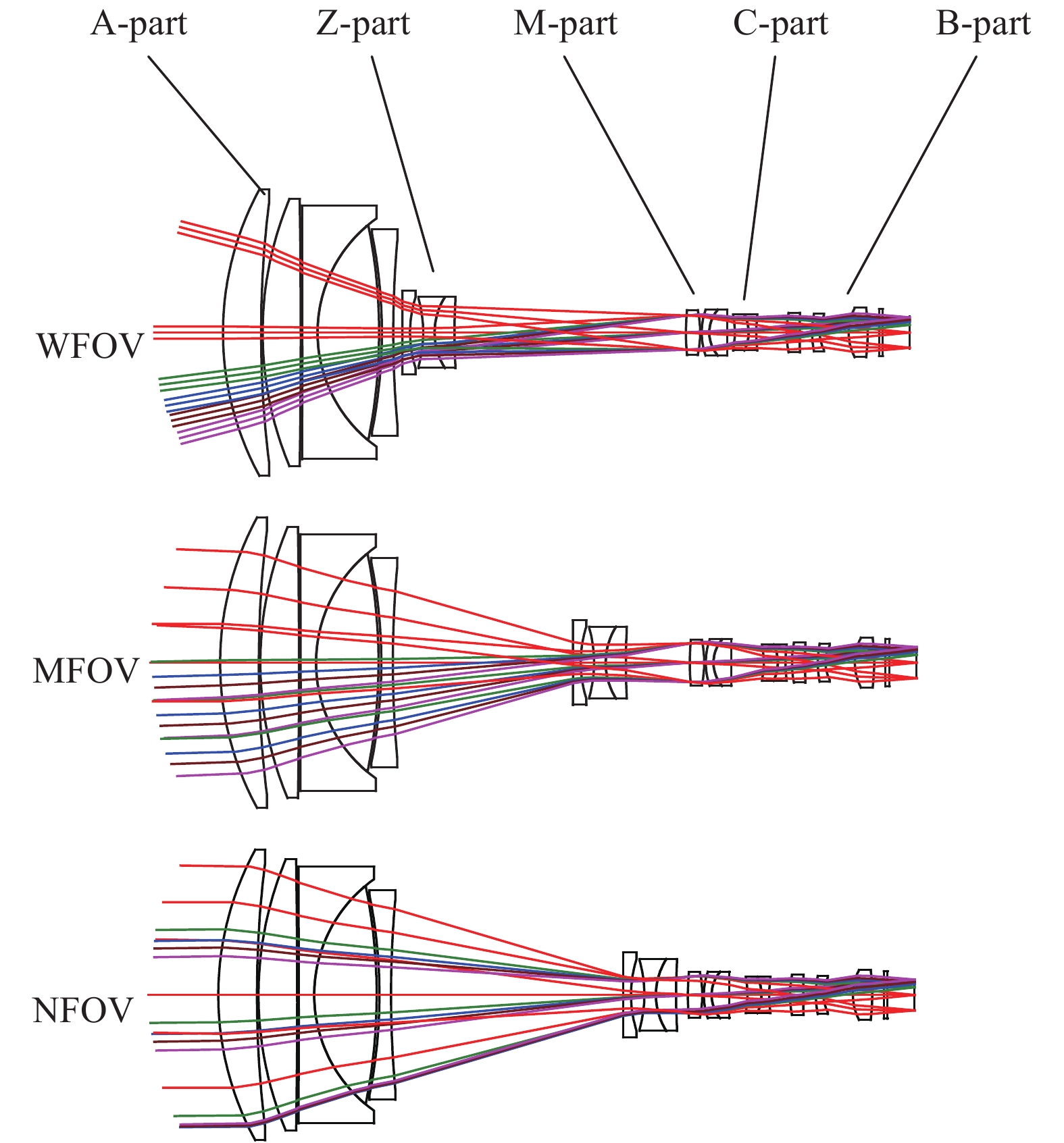
光学系统前固定镜组(A-part)承担系统主要光焦度,采用四组五片式结构,其中首片正透镜采用HZF88材料,尾片负透镜采用HZF3来平衡色差和热差;变倍镜组(Z-part)行程较大,承担整个光学系统变倍作用,采用色散能力较强的HZF88做正透镜,进行色差补偿,保证整个变倍组具有较小的残余色差;中间固定组(M-part)为典型的单透镜+双胶合结构,具有正光焦度;补偿组(C-part)具有正光焦度,主要用作补偿因变倍组移动引起的像面偏移,其中的双胶合元件具有负的合成色散系数,可保证补偿组色差的独立校正;后固定镜组(B-part)靠近像面,构成场镜结构,主要用于校正系统场曲和畸变,另外较长的后截距也给系统的滤光片切换机构预留了足够的空间[8-12]。
采用CodeV软件对上述光学系统进行优化分析,图2为可见-近红外无热化连续变焦光学系统优化结果示意图。所述系统采用HZF88、HZF3、HFK95、HZPK1、HZLAF78等七种普通光学玻璃材料,共12组16片透镜,光机选用铝合金材料,光学系统靠近物面一侧表面至焦面,总长90 mm,单透镜最大口径小于45 mm,双胶合透镜最大口径小于40 mm。

Figure 2. Optimization results diagram of visible-near infrared continuous zoom optical system
对上述光学系统不同温度、不同视场的MTF评价如表2和表3所示。可以看出,所设计的光学系统在−40~60 ℃范围内,在长焦、中焦和短焦不同位置,空间频率为180 lp/mm处均具有较好的传函分布,表明该系统具有较好的成像质量,也证明了上述设计方法的可行性。利用编写的宏程序对上述宽波段连续变焦光学系统进行凸轮曲线优化设计,图3为优化完成的变焦系统凸轮曲线示意图,可知整个变焦系统变倍补偿过程平滑无拐点,可满足工程应用要求[13-15]。
−40 ℃ 20 ℃ 60 ℃ EFL=8 mm 


EFL=70 mm 


EFL=120 mm 


Table 2. MTF of the zoom optical system in 0.48-0.68 μm at −40 ℃, 20 ℃ and 60 ℃
−40 ℃ 20 ℃ 60 ℃ EFL=8 mm 


EFL=70 mm 


EFL=120 mm 


Table 3. MTF of the zoom optical system in 0.7-0.9 μm at −40 ℃, 20 ℃ and 60 ℃

Figure 3. Resulted cam curve of the zoom lens system
取前固定镜组和焦面的轴向位置作为装调补偿,各镜组和镜组间的公差要求如下:各镜组内材料折射率公差为±0.001,阿贝数公差为±0.002;面型公差为N=3,ΔN=0.3;厚度公差为±0.03 mm;偏心公差为±0.01 mm;倾斜公差为±1′。镜组间用镜筒整合,整合公差:偏心公差为±0.03 mm,倾斜公差为±1′,均具有优良的可实现特性。对应公差条件下可见谱段的MTF概率累积分布如图4所示。

Figure 4. Cumulative probability of MTF in 0.48-0.68 μm
-
从光学系统设计的像差模型出发,将变焦系统的像差分为定组像差、动组像差和动组间像差,结合变焦系统设计中的消色差和消热差条件,简要讨论了各像差特性,论述了一种无热化连续变焦光学系统的设计方法,降低了该类系统的设计难度。作为例证,给出了一个可见-近红外连续变焦光学系统设计实例。该光学系统在所用材料皆为普通光学玻璃材料的条件下实现了8~120 mm焦距范围,可见光和近红外双段波的共孔径共焦面集成,及−40~60 ℃宽温度条件内的光学被动无热化,并且该系统具有小巧的体积、紧凑的结构、高的透过率,在整个变焦范围内都具有较好的成像质量与公差特性,可望在观瞄、监控、多谱段成像等领域获得广泛应用。目前该方法已用于类似产品的设计开发当中。
Design of visible-near infrared athermal continuous zoom optical system
doi: 10.3788/IRLA20210090
- Received Date: 2021-02-04
- Rev Recd Date: 2021-04-11
- Publish Date: 2021-09-23
-
Key words:
- optical design /
- continuous zoom /
- wide band /
- athermal /
- optical dehazing
Abstract: The primary aberration of each lens group will be changed with their movement, and the change of environment temperature will also lead to defocus, both of which will cause a lot of difficulties in the zoom lens design process. To solve this problem, aberration functions do depend and not depend on group movement were introduced based on optical aberration theory, and lens power distribution and material selection method were discussed with the achromatic and athermal design model futher. A visible-near infrared (Vis-Nir) optical system under the requirements of F/5, focal length of 8-120 mm, focal plane diameter of 6.2 mm, work waveband of 0.48-0.68 μm and 0.7-0.9 μm was designed with mechanically compensated method and optical passive athermal technology. The proposed zoom lens system, which used 7 kinds of common optical glass, consists of 12 groups 16 lenses, total length of only 90 mm, has good image quality and tolerance character among the zoom range within −40~60 ℃.


 DownLoad: