Volume 50 Issue 12
Dec.  2021
Turn off MathJax
Article Contents

Chen Xiang, Hu Xinrong, Zhang Jianhua, Li Shuai, Xue Jingjing, Ren Bin, Jin Yi. Beam pointing and coarse tracking characteristics of Tip-Tilt mirror type laser communication terminal[J]. Infrared and Laser Engineering, 2021, 50(12): 20210146. doi: 10.3788/IRLA20210146
Citation: Chen Xiang, Hu Xinrong, Zhang Jianhua, Li Shuai, Xue Jingjing, Ren Bin, Jin Yi. Beam pointing and coarse tracking characteristics of Tip-Tilt mirror type laser communication terminal[J]. Infrared and Laser Engineering, 2021, 50(12): 20210146. doi: 10.3788/IRLA20210146

Beam pointing and coarse tracking characteristics of Tip-Tilt mirror type laser communication terminal

doi: 10.3788/IRLA20210146
  • Received Date: 2021-05-10
  • Rev Recd Date: 2021-07-20
  • Publish Date: 2021-12-31
  • To realize the coarse tracking of laser communication terminal (LCT) with a single plane mirror (Tip-Tilt mirror type)and two orthogonal rotation axes, a normal vector solving algorithm for beam pointing was proposed. The coarse tracking algorithm of this type LCT was given. By using vector reflection law and matrix rotation transformation, a theoretical derivation of the tip-tilt mirror was carried out to get the analytical solution of the beam pointing model and tracking model. The effects of different installation methods on the beam pointing and distortion were discussed. The model was researched on modeling simulation and experiment respectively. The results show that the accuracy of the beam pointing model and the coarse tracking model are better than 3 µrad. The developed LCT has a coarse tracking accuracy better than 15.5 µrad (3σ), and the RMS error is better than 10.5 µrad. It meets the high-precision coarse tracking requirements of the LCT. The work has reference significance for beam pointing analysis of the Tip-Tilt mirror type scanning system and laser terminal coarse tracking.
  • [1] Cohen-Sabban J, Cohen-Sabban Y, Roussel A. Distortion-free 2-D space and surface scanners using light deflectors [J]. Appl Opt, 1983, 22(24): 3935-3942. doi:  10.1364/AO.22.003935
    [2] Li Y J, Katz J. Laser beam scanning by rotary mirrors. I. Modeling mirror-scanning devices [J]. Appl Opt, 1995, 34(28): 6403-6416. doi:  10.1364/AO.34.006403
    [3] Cai Y Q, Tong X H, Tong P, et al. Linear terrestrial laser scanning using array avalanche photodiodes as detectors for rapid three-dimensional imaging [J]. Appl Opt, 2010, 49(34): 11-19. doi:  10.1364/AO.49.000H11
    [4] Lee X B, Wang C H. Optical design for uniform scanning in MEMS-based 3D imaging lidar [J]. Appl Opt, 2015, 54(9): 2219-2223.
    [5] Artamonov S I, Gryaznov N A, Kuprenuuk V I, et al. Selection of scanners for use in lidar systems [J]. J Opt Technol, 2016, 83(9): 549-555. doi:  10.1364/JOT.83.000549
    [6] Hookman R A, Zurmehly G E, Hodgman N S. Scanning mirror design considerations for a geostationary spaceborne radiometer[C]//SPIE,1992, 1693: 318-329.
    [7] Wang M Z, Huang X X, Feng Q. Two judging methods of seamless stitching for frame sensor on the geostationary prbit: Grid method and the geometric intersection method [J]. Journal of Remote Sensing, 2017, 21(6): 871-880. (in Chinese)
    [8] Talmor A G, Harding H, Chen C C. Two-axis gimbal for air-to-air and air-to-ground laser communications[C]//SPIE, 2016, 9739: 97390G.
    [9] Kesner J E, Hinrichs K M, Narkewich L E, et al. Compact optical gimbal as a conformal beam director for large field-of-regard lasercom applications[C]//SPIE, 2015, 9354: 93540K.
    [10] Hafez M, Julliard K, Grossmann S, et al. Compact multisensor laser scanning head for processing and monitoring microspot welding[C]//SPIE, 2000, 4088: 268-271.
    [11] Hafez M, Sidler T, Salathé R P. Study of the beam path distortion profiles generated by a two-axis tilt single-mirror laser scanner [J]. Opt Eng, 2003, 42(4): 1048-1057. doi:  10.1117/1.1557694
    [12] Wang D L, Liang P, Samuelson S, et al. Correction of image distortions in endoscopic optical coherence tomography based on two-axis scanning MEMS mirrors [J]. Biomed Opt Express, 2013, 4(10): 2066. doi:  10.1364/BOE.4.002066
    [13] Lin L Y, Keeler E G. Progress of MEMS scanning micromirrors for optical Bio-imaging [J]. Micromachines, 2015, 6: 1675-1689. doi:  10.3390/mi6111450
    [14] Pokorny P. One-mirror and two-mirror three-dimensional optical scanners—position and accuracy of laser beam spot [J]. Appl Opt, 2014, 53(12): 2730-2740. doi:  10.1364/AO.53.002730
    [15] Smith T. On systems of plane reflecting surfaces [J]. Transactions of the Optical Society, 1928, 30: 68-78. doi:  10.1088/1475-4878/30/2/302
    [16] Pegis R J, Rao M. Analysis and design of plane-mirror systems [J]. Appl Opt, 1963, 2(12): 1271-1274. doi:  10.1364/AO.2.001271
    [17] Li Y J. Laser beam scanning by rotary mirrors Ⅱ conic-section scan patterns [J]. Appl Opt, 1995, 34(28): 6417-6430.
    [18] Li Y J. Single-mirror beam steering system: analysis and synthesis of high-order conic-section scan patterns [J]. Appl Opt, 2008, 47(3): 386-398. doi:  10.1364/AO.47.000386
    [19] Li Y J. Beam deflection and scanning by two-mirror and two-axis systems of different architectures: A unified approach [J]. Appl Opt, 2008, 47(32): 5976-5985. doi:  10.1364/AO.47.005976
    [20] Li Y J. Differential geometry of the ruled surfaces optically generated by mirror-scanning devices [J]. J Opt Soc Am A, 2011, 28(4): 667-674. doi:  10.1364/JOSAA.28.000667
    [21] Li Y J. Differential geometry of the ruled surfaces optically generated by mirror scanning devices: Ⅱ. Generation of helicoids and hyperbolic paraboloids [J]. J Opt Soc Am A, 2011, 28(6): 1239-1242. doi:  10.1364/JOSAA.28.001239
    [22] Anzolin G, Gardelein A, Jofre M, et al. Polarization change induced by a galvanometric optical scanner [J]. J Opt Soc Am A, 2010, 27(9): 1946-1952. doi:  10.1364/JOSAA.27.001946
    [23] Yang Y F, Yan C X. Polarization property analysis of a periscopic scanner with three-dimensional polarization ray-tracing calculus [J]. Appl Opt, 2016, 55(6): 1343-1350. doi:  10.1364/AO.55.001343
    [24] Jiang L, Wang C, Liu Z, et al. Effects on performance of a 90° optical hybrid due to rotation of a 45° reflector scanner in a free space optical communication terminal [J]. J Laser Appl, 2018, 30(3): 032012. doi:  10.2351/1.4990945
    [25] Lian Tongshu. Conjugate Theory of Reflecting Prism[M]. Beijing: Beijing Institute of Technology Press, 1988: 1-6. (in Chinese)
    [26] Zhang E, Gong Huixing. Research and application of system for offsetting image rotation from 45° rotating scan mirror [J]. J Infrared Millim Waves, 1999, 18(2): 125-132. (in Chinese)
    [27] Liu Yinnian. Analysis of the imaging characteristics and scanning traces of the 45° rotating mirror [J]. Optics and Precision Engineering, 2002, 10(1): 110-115. (in Chinese)
    [28] Hui Bin, Pei Yuntian, Wang Ganquan. Optical analysis of space two-axus scanning mirror [J]. Chinese Journal of Quantum Electronics, 2005, 22(5): 810-813. (in Chinese)
    [29] Hui Bin, Li Jingzhen, Huang Hongbin, et al. Optical analysis of space two-axis scanning mirror [J]. Infrared Technology, 2006, 28(9): 508-511. (in Chinese)
    [30] Li Shuying, Zhou Shichun. Analysis of the imaging characteristics of the two-dimensional pointing mirror [J]. Opto Electronic Engineering, 2008, 35(5): 17-22. (in Chinese)
    [31] Chen Qiang. Analysis and correction of the image aberration of 45° directional mirror [J]. Infrared and Laser Engineering, 2010, 39(2): 301-305. (in Chinese)
    [32] Wang Wu, Hong Pu, Wang Bo, et al. Characteristic analysis of two-dimensional scanning mirror rotating [J]. Optics & Optoelectronic Technology, 2015, 13(2): 82-86. (in Chinese)
    [33] Gao Duorui, Li Tianlun, Sun Yue, et al. Latest developments and trends of space laser communication [J]. Chinese Optics, 2018, 11(6): 901-913. (in Chinese) doi:  10.3788/co.20181106.0901
    [34] Tan Liying, Wu Shichen, Han Qiqi, et al. Coarse tracking of periscope type satellite optical communication terminals [J]. Optics and Precision Engineering, 2012, 20(2): 271-276. (in Chinese)
    [35] Meng Lixin, Zhao Dingxuan, Zhang Lizhong, et al. Research on acquisition and tracking system for space laser communication networking [J]. Journal of Changchun University of Science and Technology(Natural Science Edition), 2014, 37(6): 70-76. (in Chinese)
    [36] Zhang Jiaqi, Zhang Lizhong, Dong Keyan, et al. Coarse tracking technology of secondary imaging Coude-type laser communication terminal [J]. Chinese Optics, 2018, 11(4): 644-653. (in Chinese) doi:  10.3788/co.20181104.0644
    [37] Li Xiang, Li Xiaoming, Zhang Jiaqi, et al. Integrated SiC/Al lightweight tip-tilt mirror of multi-node laser communications antenna [J]. Infrared and Laser Engineering, 2019, 48(S1): S118001. (in Chinese)
    [38] Heese C, Sodnik Z, Carnelli I. Design of the optical communication system for the asteroid impact mission[C]//SPIE, 2016, 10562: 105622W.
    [39] Householder A S. Principles of Numerical Analysis[M]. New York: McGraw-Hill, 1953: 135-138.
  • 加载中
通讯作者: 陈斌, bchen63@163.com
  • 1. 

    沈阳化工大学材料科学与工程学院 沈阳 110142

  1. 本站搜索
  2. 百度学术搜索
  3. 万方数据库搜索
  4. CNKI搜索

Figures(14)

Article Metrics

Article views(498) PDF downloads(85) Cited by()

Related
Proportional views

Beam pointing and coarse tracking characteristics of Tip-Tilt mirror type laser communication terminal

doi: 10.3788/IRLA20210146
  • China Academy of Space Technology (Xi’an), Xi’an 710000, China

Abstract: To realize the coarse tracking of laser communication terminal (LCT) with a single plane mirror (Tip-Tilt mirror type)and two orthogonal rotation axes, a normal vector solving algorithm for beam pointing was proposed. The coarse tracking algorithm of this type LCT was given. By using vector reflection law and matrix rotation transformation, a theoretical derivation of the tip-tilt mirror was carried out to get the analytical solution of the beam pointing model and tracking model. The effects of different installation methods on the beam pointing and distortion were discussed. The model was researched on modeling simulation and experiment respectively. The results show that the accuracy of the beam pointing model and the coarse tracking model are better than 3 µrad. The developed LCT has a coarse tracking accuracy better than 15.5 µrad (3σ), and the RMS error is better than 10.5 µrad. It meets the high-precision coarse tracking requirements of the LCT. The work has reference significance for beam pointing analysis of the Tip-Tilt mirror type scanning system and laser terminal coarse tracking.

  • 光学扫描系统根据应用类型可分为:空间角度扫描系统和表面扫描系统[1-2]。空间角度扫描是指在空间角度方向上进行主动或被动探测成像,如激光雷达[3-5]、航天遥感[6-7]和激光通信[8-9];表面扫描是针对某一特征表面进行扫描或成像,如激光加工[10-11]和医学成像[12-13]。扫描系统的功能是增加光学系统的指向范围或成像视场角。为实现光束的二维扫描通常将单个平面镜或两个平面镜固定在互相正交的两个旋转轴系上[14],其中单平面镜二维扫描系统(也称摆镜)具有结构紧凑、扫描回转半径小的特点而被广泛研究和应用。

    由于扫描系统的广泛应用价值,许多相关的重要研究成果得到报道,其中包括平面镜系统的理论研究[15-16],在特定观察平面内对不同扫描光束的特性研究[17-21],扫描光束的偏振特性研究[22-24]。连铜淑[25]以周视扫描镜、准直观测镜的应用研究为背景提出了平面镜系统转动定理,奠定了摆镜系统的理论基础。在以扩展成像视场为目标的各类应用中[26-32],研究者分别就45°摆镜或60°摆镜扫描引起的像旋、扫描畸变、光束指向和成像特性进行了深入探讨。鉴于摆镜转动时光束指向与轴系转动顺序相关,摆镜轴系的不同安装方式对光束指向的影响规律十分复杂。在激光通信[33]领域,潜望式[34-35]和库德式[36]激光终端的粗跟踪模型和算法均取得了有益的研究成果,而摆镜式激光终端的相应工作还尚未进行深入研究[37]

    文中提出一种求解摆镜式扫描系统光束指向的法矢量求解算法,以摆镜式激光终端Optel-D[38]为例,研究此类终端的粗跟踪特性,进一步给出摆镜式激光终端粗跟踪算法。首先,基于矢量形式的反射定律,研究典型平面镜安装角度下,不同扫描镜摆角随着镜面反射光束指向的旋转变换规律;然后,建立摆镜式激光终端的粗指向解析模型,并给出求解算法。通过建立仿真模型对跟踪算法的准确性和跟踪精度进行验证;最后,利用研制的激光终端对粗跟踪算法的精度进行实验研究。该工作可实现摆镜式激光终端对目标的快速粗跟踪。

  • 图1所示,常见的二维扫描平面镜系统如MEMS扫描镜、快反镜和二轴跟踪架反射镜,可直观抽象成三个组成部分:(1)用于反射光线的平面反射镜,(2)方位旋转轴P1,(3)俯仰旋转轴P2。图(a)为MEMS反射镜,图(b)为快反镜,图(c)和图(d)所示为两轴跟踪架反射镜,图(e)和图(f)为摆镜的简化模型,其中图(e)旋转轴 P 2平行于镜面,图(f)旋转轴 P 2与镜面夹角为 γ。在定坐标系XYZ中,反射镜的单位法矢量定义为N0=[sinγ, −cosγ, 0]T;方位角定义为平面镜绕P1轴旋转α,俯仰角定义为平面镜绕轴P2旋转β,外轴可带动内轴转动。单位法矢量N随着旋转角度αβ而变化,角度γ为固定的常数,由镜面安装方式和光路设计决定,典型的工程应用通常选择γ=45°或γ=30°。

    Figure 1.  Schematic diagram of two-dimensional scanning Tip-Tilt mirror

  • 求解光束经过平面镜的光束指向的基本方程是矢量形式的反射定律,如下所示:

    式中:N=[Nx, Ny, Nz]T为镜面的单位法矢量;A=[Ax, Ay, Az]T为入射光线单位矢量,B=[Bx, By, Bz]T为反射光线单位矢量。矩阵R为基本反射矩阵[39]

    如公式(1)和公式(2)所示,对给定的矢量A求解矢量B的过程等同于求解平面镜绕轴旋转αβ后的反射矩阵R(N)。

    矢量A绕转轴单位矢量P=[Px, Py, Pz]T逆时针旋转角度θ后得到矢量A′=SP,θA,其中SP,θ描述为:

  • 对于给定的入射光束,利用公式(1)和公式(3)求解出射光束的思路可分为两种。一种较为直观的方法是在定坐标系下利用公式(3)求解平面镜转动后的法矢量,代入公式(1)进行光束反射变换得到出射光束指向,称为法矢量求解法。另一种是连铜淑[25]提出的坐标变换法,首先在镜面上建立动坐标系,将入射光束进行旋转变换至动坐标系下,并进行光束反射变换,最后对出射光线再进行旋转变换至定坐标系。

  • 图2所示,首先给定入射光矢量A0,平面镜初始状态法矢量N0,反射镜旋转轴矢量P1P2。然后利用公式(3)求解镜面法矢量N0绕旋转轴P1旋转角度α后的法矢量:

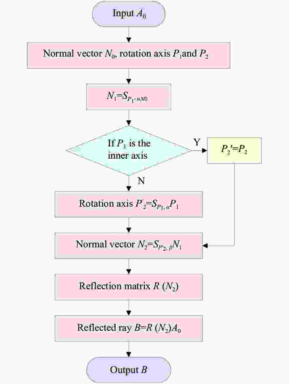
    Figure 2.  Flow chart of the proposed normal vector solution algorithm

    若旋转轴P1为内轴,则外轴P2将不随P1轴旋转而运动,定义第二次的旋转轴P2′=P2;若旋转轴P1为外轴,则内轴P2将随P1轴旋转而运动。考虑不同形式的内轴与外轴安装方式,可将第二次旋转轴可描述为

    再次利用公式(3)求解矢量N1绕旋转轴P2′旋转角度β后的法矢量,得到镜面经过两次旋转后的法矢量为:

    最后将公式(6)代入公式(1)从而得到反射光束:

  • 利用矢量求解法求解典型应用情况下的光束指向,以研究其运动规律对指向的影响,其中Z=[0, 0, 1]TQ=[cosγ, sinγ, 0]T。定义比值ε描述两旋转轴的单独绕中心旋转对反射光夹角的影响比例:

    图3所示,45°反射镜绕ZQ轴旋转在旋转中心位置具有极小值ε=1.414 2,绕ZX轴旋转在旋转中心位置具有极小值ε=2;而30°反射镜ZQ轴旋转在旋转中心位置处具有极小值ε=1.154 7,绕ZX轴旋转在旋转中心位置具有极小值ε=1.333 3。并且在扫描角度范围5°以内,该比例的绝对误差在0.001以内,可见两旋转轴的线性度较好,并且比值趋于稳定值。比较45°安装和30°安装两种典型方式,结合数据仿真结果来看,对扫描成像系统,30°的安装方式两扫描轴的比例系数更接近于1,意味着同等驱动条件下其扫描畸变要相对较小。

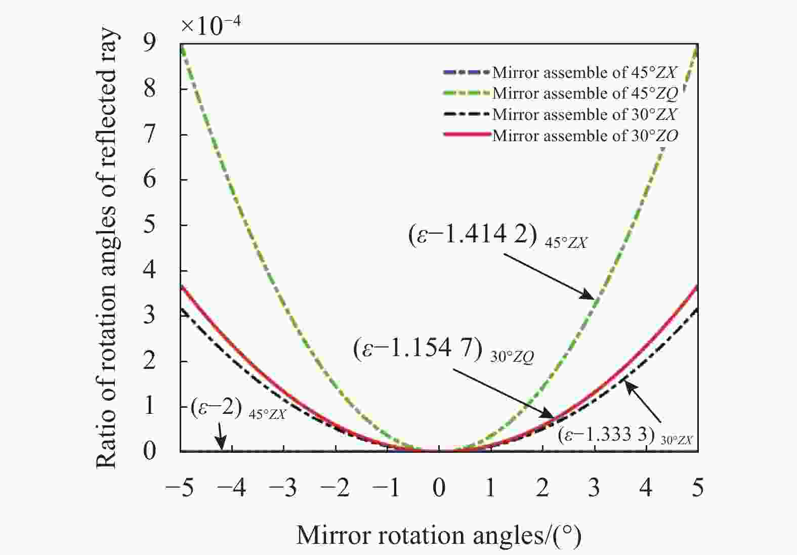
    Figure 3.  Ratio of rotation angles of reflected rays vary with the mirror rotation angles

    图4所示,坐标平面XOY中的反射射线的投影矢量与Y轴负方向之间的角度定义为方位角θ1YOZ平面中的投影矢量与Y轴负方向之间的角度定义为俯仰角θ2,视场角θ定义为B(α, β)和B(0,0)之间的夹角:

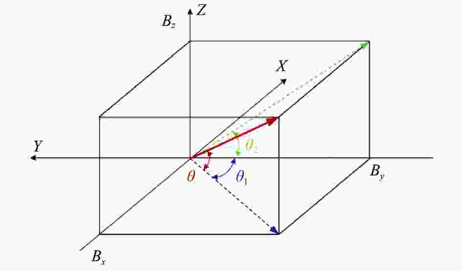
    Figure 4.  Field angle of view for the reflected light

    图5给出了45°典型安装角度方式下内外轴不同旋转组合对扫描视场角的影响,P1ZX表示P1为内轴,先旋转内轴Z轴,后旋转外轴X轴,P2ZX表示P2为内轴,先旋转内轴X轴,后旋转外轴Z轴,图中的其他描述也是类似。图5中在相同的旋转轴设置情况下(P1ZXP2ZX),虽然出射光的视场角描述不同,但是畸变形式与旋转轴的先后顺序相关性较小;对比P1ZQP2ZQ也可得出类似的规律。

    Figure 5.  Relationship between the azimuth angle, elevation angle and field of view of the 45° reflector under different rotation modes with two-dimensional scanning

  • 粗跟踪的过程是根据跟踪探测器的脱靶量坐标,求解粗瞄机构的执行角度量,驱动粗瞄机构两轴进行对应角度量的转动,实现目标跟踪。考虑到粗跟踪的精度较低,加上需要抑制卫星平台的振动对光束指向和跟踪的影响,通常还需要增加精指向机构(FPA)最终实现高精度的目标跟踪。

  • 根据摆镜式激光通信终端的工作特点,需要建立如图6所示的三个右手坐标系研究光束指向和跟踪特性。终端主体坐标系固定在星上,定义为定坐标系XYZ;粗瞄机构带动平面镜进行两轴旋转,定义瞄准机构坐标系,即动坐标系X1Y1Z1;粗瞄机构指向空间某一位置时,光束相对平面镜的法向存在随俯仰角运动的夹角,定义光束指向坐标系X2Y2Z2。其中动坐标系与定坐标系之间存在方位和俯仰二维运动变换关系;动坐标系与指向坐标系之间存在俯仰向一维运动变换关系,在零位时,三个坐标系重合。中心视场的光轴指向始终保持与Y2轴平行,若摆镜保持方位为零位,而俯仰向转动角度θEl后,动坐标系相对定坐标系转动θEl,而指向坐标系相对定坐标系转动2θEl

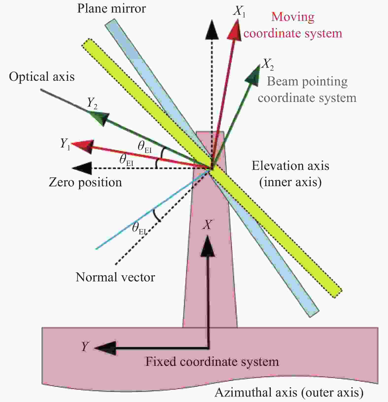
    Figure 6.  Definition of coordinate systems for the Tip-Tilt mirror CPA

    图6所示,结合建立的坐标系:当粗瞄机构的俯仰轴和方位轴处于零位时,CPA反射镜法矢量为N0=1/2[$ - \sqrt 2 $,$\sqrt 2 $,0]T,俯仰轴为Z轴,方位轴为X轴;当CPA运动过程中,方位轴保持不动始终为X轴,而俯仰轴变为Z1轴。精指向镜(FPA)法向量为−N0不随指向变化,分光镜(DBS)法向量为N0不随指向变化,除摆镜外其余部分均相对定坐标系静止。

  • 考虑一般情况下,当CPA处于某非零位状态时,在指向坐标系中,终端接收的轴外视场的入射光矢量可描述为:

    式中考虑到激光终端的应用场景,其跟踪视场(θ, φ)一般在1~2 mrad量级,可对轴外视场取一级近似以简化求解过程。在定坐标系中,令θAzθEl分别为粗瞄机构方位和俯仰轴相对定坐标系转动的角度(方位角,俯仰角),n为望远镜放大率。轴外光束首先入射到终端粗瞄机构反射镜上,然后顺次经过望远镜、FPA反射镜、DBS分光镜、信号跟踪镜头会聚后入射CCD探测器上,理想情况下可得到信号跟踪探测器上的入射光矢量为:

    式中:TCPA=R(Sex,θAzSez,θElN0)为粗瞄机构反射镜作用矩阵;TTLA=[ex, ney, nez]为望远镜作用矩阵;TFPA=R(−N0)为精跟踪反射镜作用矩阵;TDBS=R(N0)为分光镜作用矩阵;A0′=Sex,θAzSez,2θElA0为定坐标系中描述的入射光矢量。

    当入射光束为公式(10)所定义的轴外视场时,激光终端对应在CCD焦平面上光斑位置为(Y, Z),考虑CCD前的聚焦透镜焦距为f,该坐标将对应于入射至CCD焦面上的光矢量:

    通过公式(11)和公式(12)求解,可得到轴外视场角:

    公式(13)为摆镜式激光终端探测器CCD焦平面上光斑位置与终端入射光束指向偏角关系。可见,入射光束相对光轴(中心视场)的夹角可通过CCD光斑坐标位置来表示,并且是终端粗瞄机构的姿态参数的函数。与潜望式和经纬仪式终端[34, 36]不同,摆镜式激光通信终端的偏向角只与方位旋转角θAz有关,而于俯仰偏转角θEl无关。

  • 通过控制激光终端CPA转动实现对信号光的跟踪,该过程是通过转动方位轴和俯仰轴运动(ΩAz, ΩEl),使信号光出现在CCD探测器靶面中心跟踪点。虽然公式(13)已求得轴外视场相对中心视场跟踪点的偏角,但是由于该偏角是在指向坐标系中描述的,而俯仰旋转轴在动坐标系中,方位轴在定坐标系中,并不能直接通过旋转偏角(θ, φ)实现对目标的跟踪,因此需要研究(ΩAz, ΩEl)与(θ, φ)的关系。

    在动坐标系中,方位轴和俯仰轴旋转矩阵分别可描述为:

    式中:俯仰向需要考虑平面镜存在偏向角的二倍关系。在指向坐标系中,旋转方位轴和俯仰轴,使得中心视场光束变为轴外视场的过程可描述为:

    对公式(15)进行化简可得到:

    求解方程组可得到方位轴和俯仰轴的执行量:

    公式(17)结合公式(13)即为摆镜式激光终端用于CCD测角的跟踪模型。

    终端工作时通过电机码盘的反馈可以获得相对于粗瞄机构基准坐标的方位轴角度和俯仰角度,同时通过探测器CCD可以实时获得入射光斑相对于CCD视场中心位置的参量。从而可以计算得到实现目标跟踪而需要的控制系统的角度参量,完成激光通信过程中的粗跟踪。

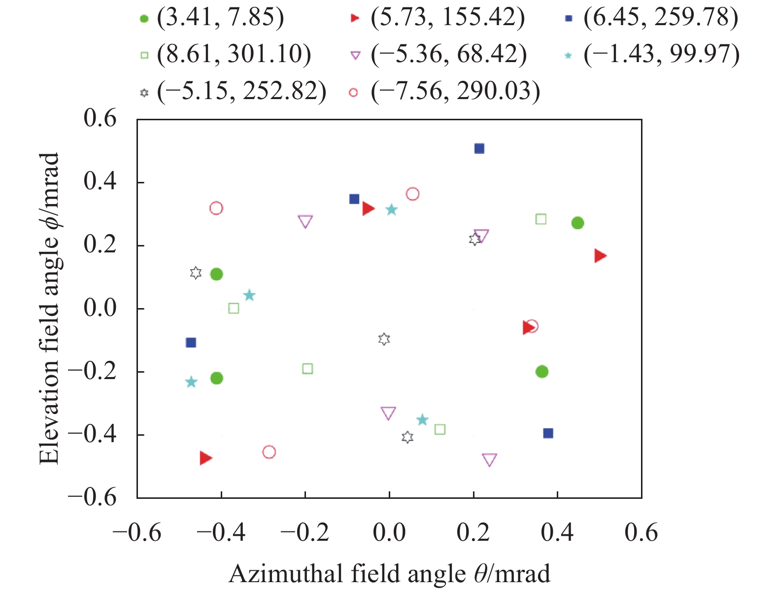
  • 利用图7中建立的光路仿真模型,验证跟踪模型的精度与正确性。由于粗瞄机构方位向可实现0°~360°旋转,对应于四个象限,而俯仰向可实现−10°~10°转动,对应于两个象限,共存在八个指向空间;而指向坐标系中轴外视场角存在四个象限。如图8所示,首先在八个指向空间分别进行随机的指向选择,对应于图中八组符号标示;然后分别对每种指向进行四种轴外视场角随机选择,共获得覆盖全指向空间和轴外视场的32组随机指向。

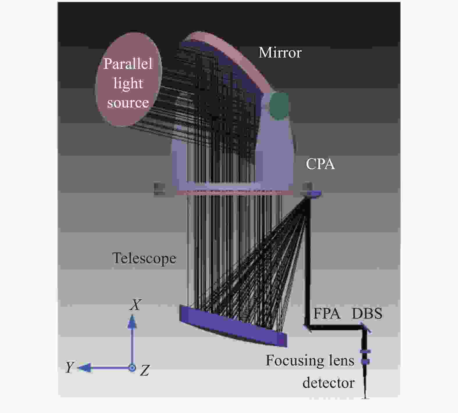
    Figure 7.  Optical simulation model of the Tip-Tilt mirror LCT

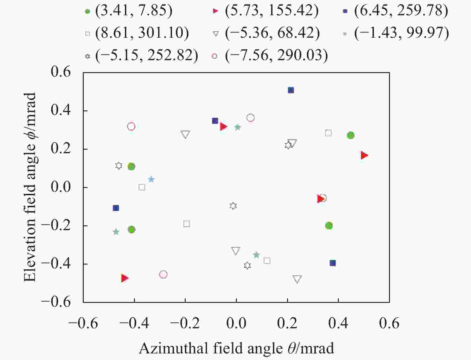
    Figure 8.  Random sampling of off-axis field beams in different pointing areas

    对于给定的视场输入(θ, φ),借助图7中建立的模型,将平行光源指向设置为(θ, φ),仿真光路经过激光终端后在探测器上的坐标(Y′, Z′),用实际在探测器焦平面上测试得到的坐标值(Y′, Z′)与公式(13)理论解算的坐标(Y, Z)的差值,并采用系统焦距对该差值进行归一化来描述光束传输模型的误差

    利用公式(17)求得的方位、俯仰执行角度,转动仿真模型的方位轴和俯仰轴,用实际在探测器焦平面上测试得到的坐标值(Y′, Z′)与中心视场坐标(Y0, Z0)的差值进行焦距归一化描述跟踪模型的误差:

    图8中的各组随机指向分别采用图7中的光路模型进行试验验证,得到的光束传输误差如图9所示,跟踪误差如图10所示。由于光束传输模型对轴外视场角(θ, φ)采用了一级近似,因此传输误差为2.5 μrad。而跟踪模型对视场角是按照准确值计算的,误差为0.3 μrad。综合来看,光束传输模型与跟踪模型相结合,对跟踪精度的影响优于3 μrad,能够满足激光通信终端对粗跟踪的精度要求。

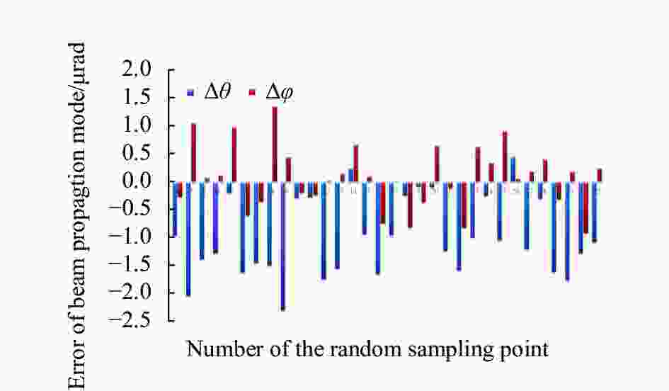
    Figure 9.  Error of the beam propagation model

    Figure 10.  Error of the proposed tracking model

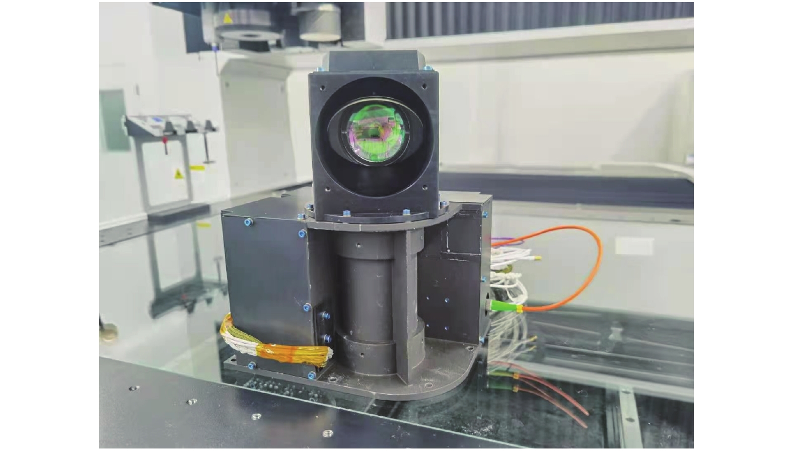
  • 为验证摆镜式激光终端粗跟踪算法的正确性,在实验室条件下搭建了光路,并测试了该算法的跟踪精度。研制的摆镜式激光终端实物如图11所示。实验原理如图12所示,首先通过调整终端姿态,使平行光管出射的平行光入射到被测激光终端CCD焦平面中心;记录当前CCD光斑位置,粗瞄机构码盘数据;控制通信端终端粗瞄机构的方位轴、俯仰轴小角度转动。通信终端粗瞄机构姿态变化后,入射到接收端CCD平面上的光斑坐标将相应的发生偏移。记录每一次通信终端方位轴和俯仰轴相对于终端粗瞄机构坐标系的姿态角度以及相应的CCD平面上的光斑坐标。将CCD上的光斑位置以及接收终端的姿态参量代入公式(17),得到的计算结果与每次接收端终端偏离角度进行对比,得到跟踪误差。

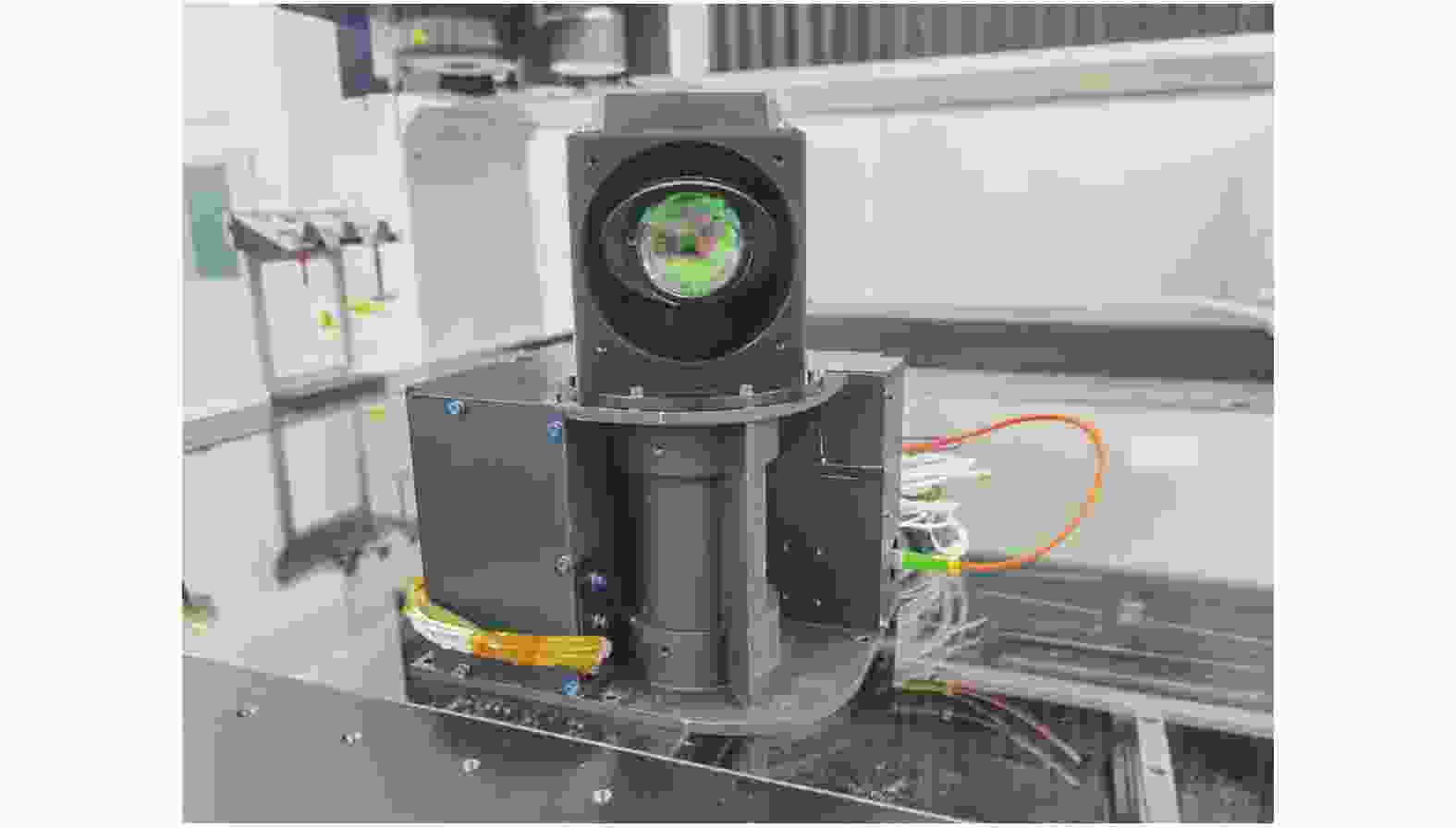
    Figure 11.  Physical image of Tip-Tilt mirror LCT

    Figure 12.  Schematic diagram of the experiment

    图13为实测方位和俯仰脱向的脱靶量,方位跟踪最大误差为14.16 μrad (3σ),均方根误差为9.16 μrad;俯仰向最大跟踪误差为15.47 μrad (3σ),均方根误差为10.09 μrad,能够满足激光终端对粗跟踪的精度要求。

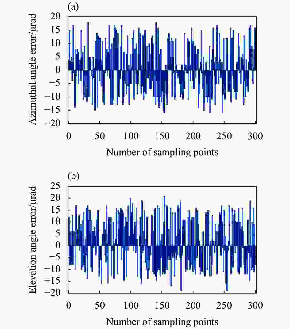
    Figure 13.  Coase tracking error of the laser terminal. (a) Azimuth; (b) Elevation

    对比实验结果与仿真结果,可以发现实验误差大于模型误差,这些误差的来源是由于光学系统的加工和装配误差,导致系统存在像差、畸变、焦距误差,为进一步提高跟踪精度,需要精指向镜(FPA)闭环校正粗跟踪的残余误差,以达到更高的跟踪精度。

  • 具有两个正交扫描轴的单镜系统广泛应用于空间遥感,激光通信和高精度复合轴跟踪系统。文中针对摆镜式激光通信终端的粗跟踪问题,提出了求解光束指向的法矢量求解算法,同时给出了该类终端的粗跟踪算法。通过采用矢量形式的反射定律和矩阵旋转变换定律,得到了摆镜的光束指向模型和跟踪模型,并讨论了不同安装方式对光束指向和畸变的影响。分别利用光学仿真和实验对激光终端的光束指向模型和粗跟踪模型进行了验证,结果表明跟踪模型精度优于3 µrad,而激光终端粗跟踪精度最大误差优于15.5 μrad (3σ),均方根误差优于10.5 μrad,能够满足激光通信终端对高精度粗跟踪的使用要求。该研究结果对摆镜式扫描系统的光束指向分析和激光终端粗跟踪具有借鉴意义。

Reference (39)

Catalog

    /

    DownLoad:  Full-Size Img  PowerPoint
    Return
    Return