


-
随着机器视觉技术的发展,非接触式单目视觉测量越来越多地应用于精确确定两个物体的三维相对位姿关系[1],并广泛运用于军事、航天、航空、工业等不同领域。单目测量系统根据小孔成像模型建立空间目标点与对应像点的映射关系,进而解算空间目标点的坐标系与相机坐标系的位姿关系[2]。单目测量系统的目标可分为合作目标和非合作目标两类[3]。合作目标需要在被测量物体表面安装或喷涂靶点,其特征提取简单和准确,但对安装或喷涂要求较高;非合作目标根据被测量物体表面特征点进行测量,其对特征提取算法要求较高[4-5]。
单目视觉测量由于其非接触式、成本低、使用灵活等优点成为了研究热点。参考文献[6]研究了基于点特征的单目视觉测量算法。参考文献[7]提出一种基于红外LED的高效、准确和鲁棒的位姿测量系统,使用P3P算法估算目标的位姿,并使用最小化重投影误差优化目标的位姿。参考文献[8]中研究非共面的目标参数单目位姿测量模型以及测量误差模型并优化相关参数,以获得最佳的位姿测量精度。视觉测量广泛运用于航天器中,根据空间飞行器的星箭对接环部件,利用单圆特征求解得到两个位姿解并通过参考点到圆心距离不变剔除虚假解[9]。参考文献[10]提出一种多特征融和的非合作航天器位姿测量方法,将航天器的通用设备作为识别的特征,通过区域检测和线检测结合来差别这些特征。参考文献[11-12]中研究了单目视觉用于机器人标定的方法。亚像素技术作为提高视觉测量精度的方法之一,可以在一定程度上补偿由硬件造成的误差[13]。参考文献[14]最早使用正交的Zernike矩检测亚像素边缘。参考文献[15]中通过Zernike矩进行棋盘格标定板的角点定位用于相机校准和位姿检测。Zernike矩进行亚像素定位需要设置有关阈值。
视觉测量的关键在于特征的提取,而特征提取的关键在于目标的分割。现在神经网络对复杂环境下的图像分割取得较好的效果[16-17],但其需要大量的数据进行训练,而且模型较大不适合在微型集成系统中使用。基于水平集演化的图像分割方法[18-19],计算量大、相关参数难以确定;其迭代次数少分割不出目标,迭代次数多导致目标过分割。参考文献[18]的方法是基于边缘,其需要正确的初始化,同时容易受到伪边缘的干扰减缓或停止演化。参考文献[19]的方法基于区域,抗干扰能力强,但提取边界不够准确。基于聚类的图像分割是基于某些相似性度量将图像划分为均匀且不重合的区域[20-21],由于目标边缘的模糊,导致边缘分割不准确,从而导致特征提取不够准确。阈值分割因其简单高效,在图像分割中扮演重要角色[22],阈值分割的关键在于选取合适的阈值。
针对单一方法难以取得好的边缘提取结果,提出了一种多方法融合的非合作目标边缘提取方法。该方法将图片像素值聚为3类(目标、高光背景和暗光背景),然后对每两类进行Otsu阈值分割得到的二值图片后进行相或操作进而分割出目标,将分割后的图像取反后通过保留面积最大的连通域去除分割出来的伪目标,最后通过Zernike矩进行亚像素边缘的细化。在此基础上根据提取的特征进行位姿测量实验。
-
单一方法难以同时兼顾图像的全局信息和局部信息,因此提出多方法融合的边缘提取方法。具体流程如图1所示,主要通过高斯滤波、K-Means聚类[23]、类间两两Otsu阈值分割[24]、分割后的图像进行或操作、图像取反保留最大连通域得到目标图像、提取目标边缘、Zernike矩亚像素边缘精定位[14]、输出亚像素目标边缘。

Figure 1. Image segmentation and sub-pixel edge positioning process
上述流程创新点如下:
(1)基于图像的全局和局部信息进行目标分割,针对图像边缘信息较复杂的情况具有较好的鲁棒性。基于全局信息对图像像素值进行聚类,对类间的像素值进行两两阈值分割是基于局部信息分割。
(2)将分割后的图像进行或操作后,由于金属表面的纹理和复杂光照导致图像出现反光和背光,出现孤立分割小区域,图像取反保留最大连通域得到目标图像,处理速度快,效果好。
(3) Zernike矩亚像素边缘定位可进一步提高目标的边缘位置,相关参数可根据边缘邻域像素值信息自适应更新。
-
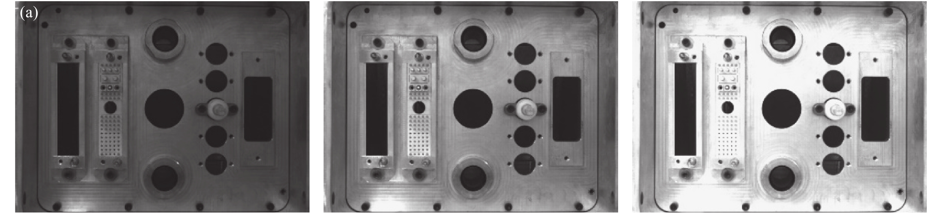
实验对象为某线缆对接装置,见图2。包括供应端和接收端,供应端由执行机构、自适应机构和CCD相机等组成,CCD相机安装于自适应机构上。相机为海康威视的MV-CE100-30GM,分辨率为3856×2764,镜头为MVL-HF1228M-6MP。装置对接前需要知道供应端自适应机构和接收端的相对位姿,采用非合作目标位姿检测,故需要提取图2(c)虚线方框内孔的边缘,拟合出圆心进行位姿检测,圆心的世界坐标由上到下依次为(0,−85,−25)、(0,0,0)、(0,85,−25)。机械定位机构保证内孔均在图2(c)的虚线方框内。

Figure 2. Original equipment image. (a) Actuator; (b) Receiver; (c) Features on the receiver
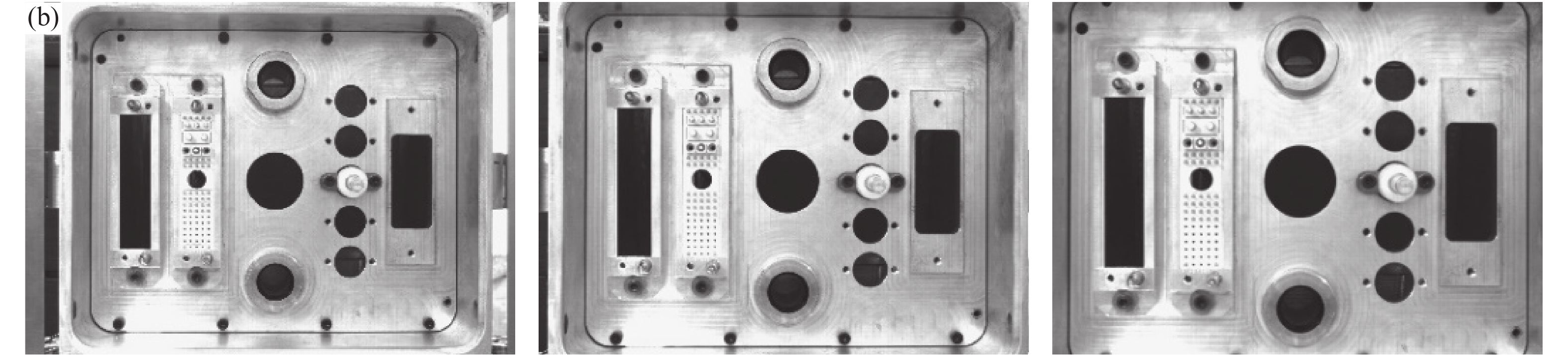
采集了85组图片,其中为了验证算法的正确性,在同一个曝光度采集了17个不同位置的图片,位置从远到近依次减少10 mm;为了验证算法的鲁棒性,在同一个位置采集5种不同曝光度(依次增强)下的图片,如图3所示。

Figure 3. Pictures under different settings. (a) Images with different exposures in the same position; (b) Images with different positions in the same exposure
-
图3中的材料为铝合金,铝合金在拍照时会出现反光的现象,导致出现亮光背景和暗光背景。为了解决这个问题,通过K-Means算法将图像的像素值分为3类,第1类是目标像素值,第2类是亮光的背景像素值,第3类是暗光的背景像素值,分类的结果如图4(b)所示。如果只将图像的像素值分为目标和背景两类,将会导致部分的背景被归类为目标类,致使边缘提取失败。

Figure 4. Image of threshold segmentation process after classification. (a) Original image; (b) Image after clustering; (c) Results of segmentation of class 1 and class 3 pixel values; (d) Results of segmentation of class 1 and class 2 pixel values; (e) Results of class 2 and class 3 pixel value segmentation; (f) The result of XOR of figure (d) and figure (e); (g) Results of figure (c), figure (d), figure (e) or operation; (h) The target obtained by removing the pseudo-connected components according to the area relationship of the connected components after inverting figure (g)

从图4(b)看出在边缘处附近存在着3类像素值,目标分割对阈值比较敏感。针对这种情况,将3类像素值进行两两阈值分割,剩下类的像素值视为0,使用Otsu算法进行分割。分割得到的3张二值图像进行或运算合并后得到初步的分割图像,其中包含着多个孤立小区域,见图4(g)。将图片取反后保留面积最大的连通域即是目标,见图4(h)所示。通过图4可以看出,分类后再Otsu阈值分割,可准确的将目标分割出来。
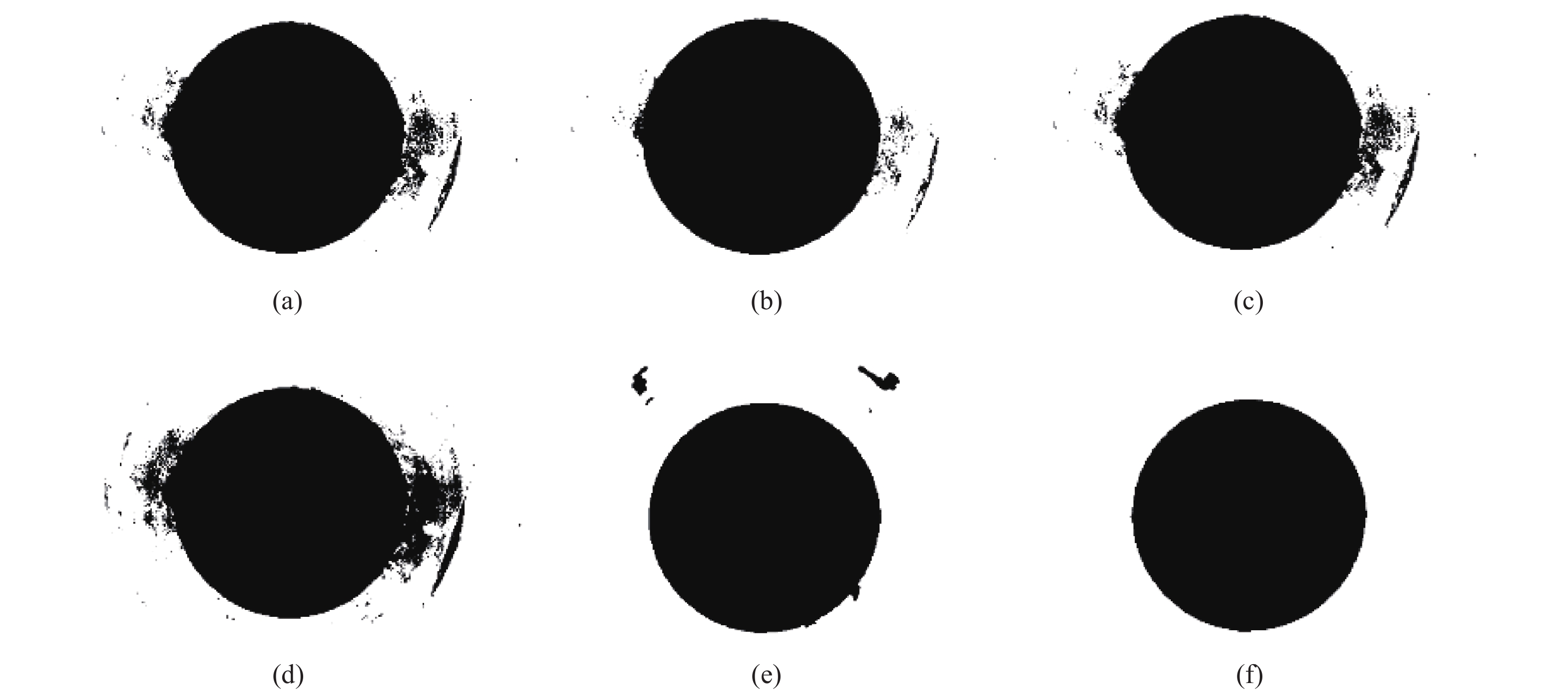
图5展示了各种分割算法效果对比,效果最好的是多方法融合的图像分割方法,其次是距离正则化水平集演化图像分割方法,其他方法均未有效地分割出目标。其他基于阈值分割算法基于全局信息寻找最佳阈值,多方法融合的图像分割方法先基于全局像素值进行分类,在不同类间进行阈值分割,既充分考虑全局信息又顾及目标边缘局部细节信息,故效果较好。多方法融合的图像分割方法思想是基于多阈值,但不是基于全局的阈值,而是不同类间的阈值。图5(c)中的多阈值是基于全局像素值进行多阈值分割,但由于金属表面的纹理易导致亮光背景和暗光背景,在目标边缘的像素值较复杂,未能考虑目标边缘的局部信息故其不能有效地分割出目标。距离正则化水平集演化图像分割方法需要正确的初始化,同时计算量较大,其分割一张图片需要226 s,而文中的方法只需要0.35 s,在实际应用中时效性太差。

Figure 5. Comparison of various segmentation methods. The picture corresponds to circle 3 in the first picture in the first row in Fig. 4. (a) Otsu; (b) Global histogram threshold using Otsu's method; (c) Multilevel image thresholds using Otsu’s method; (d) Iterative threshold segmentation method; (e) DRLSE algorithm[18]; (f) Proposed method
-
阈值分割后的边缘为单像素,为了进一步提高位姿检测的精度,采用了参考文献[14]中Zernike矩进行边缘亚像素细化。图6为理想的亚像素边缘检测阶跃模型。图6(a)是原始边缘图像,图6(b)是旋转
$\phi $ 后的边缘图像。边缘两侧的灰度值分别为h和h+k,其中k为灰度差。边缘到原点的理论距离为l,l与x轴的夹角为$\phi $ 。
Figure 6. Sub-pixel edge detection ideal step model. (a) Original edge image; (b) Rotated edge image
图7(a)是棋盘格标定板的一个角点。图7(b)是Zernike亚像素边缘和分类后阈值边缘的对比,Zernike亚像素边缘可修正分类后阈值分割的边缘。从图7(a)可以看出,由于相机像素间会有相互影响导致理想的边缘产生边缘模糊,可以看出边缘模糊在5个像素左右,所以Zernike掩膜的大小设置为
${\rm{5}} \times {\rm{5}}$ 。
Figure 7. Edge detail. (a) A corner of the checkerboard calibration board; (b) Zernike sub-pixel edges and thresholded edges after classification
根据参考文献[14]的方法计算出Zernike的边缘参数后,只有满足公式(1)的点是亚像素边缘上的点。
其中,
$l$ 应小于一个像素,参考文献[14]推荐${l_{th}} = \sqrt 2 {\rm{/2}}$ 。算法创新点之一:${k_{th}}$ 为粗边缘内3像素邻域的平均像素与外3像素邻域的平均像素差的一半。由于模板的放大效应[25],修正后的亚像素边缘坐标如下:式中:
$({x_s},{y_s})$ 是亚像素边缘坐标;$(x,y)$ 是粗边缘的坐标;N为Zernike模板的大小。 -
使用三个不共线的特征点求解位姿,特征点为三个内孔的拟合圆心,见图2(c)。机械结构定位保证了三个内孔会在虚线的方框内,方框在图像中的坐标是提前设定的,进行特征提取时,只需处理方框内的图像即可,可缩短计算时间和提高边缘的准确性。
在图8中,
${o_w} - {x_w}{y_w}{{\textit{z}}_w}$ 是世界坐标系,${o_c} - x{}_c{y_c}{{\textit{z}}_c}$ 是相机坐标系。点A、B、C在世界坐标系下的坐标已知,求出点A、B、C在相机坐标系下的坐标,即可求出世界坐标系与相机坐标系的相对位姿。根据余弦定理有:
令
${O_c}A = x{O_c}C$ ,${O_c}B = y{O_c}C$ ,$p = 2\cos \alpha $ ,$q = 2\cos \beta $ ,$r = 2\cos \gamma $ ,$A{B^2} = v{O_c}{C^2}$ ,$B{C^2} = aA{B^2}$ ,$A{C^2} = bA{B^2}$ ;则公式(3)化简后得:其中,
$p$ 、$q$ 、$r$ 、$a$ 、$b$ 是已知量,通过吴消元法即可求出$x$ 、$y$ ,则可以求出${O_c}A$ 、${O_c}B$ 、${O_c}C$ ,则$A = \overrightarrow {{O_c}a} \cdot \left\| {{O_c}A} \right\|$ ,$B = \overrightarrow {{O_c}b} \cdot \left\| {{O_c}B} \right\|$ ,$C = \overrightarrow {{O_c}c} \cdot \left\| {{O_c}C} \right\|$ 。
Figure 8. Diagram of pose solution
-
为了证明所提方法的有效性,供应端从远到近依次递减10 mm共17位置点,最远处距离为795.53 mm,最近处距离为634.64 mm,每个位置采集5种曝光度的图片。通过P3P位姿解算[26],可得到4组解,由于机构的粗定位可保证供应端自适应机构和接收端的距离和姿态在一定误差范围内,根据这个条件可以确定唯一解。通过采集的图片,可以求出对应位置的自适应机构和接收端的相对位姿。根据平移向量,计算出每种曝光度下每两个相邻位置点的相对距离,每两个相邻位置点的实际距离为10 mm。每种曝光度有16个相对距离,下文对测量误差(相对距离减去实际距离)进行分析。采用图5中提到的方法进行目标分割然后提取特征求解位姿并进行误差分析。由图5可以看出其他方法分割的目标部分边缘不准确,通过最小二乘法拟合圆心和半径,然后根据圆心和半径将误差较大的点去除,再重新拟合直至圆心和半径均收敛。使用文中所提方法提取特征后求解位姿平均一张图片需要1.81 s,而其他几种方法平均时间在1 s左右波动,虽然文中所提方法计算时间比其他方法略长,但文中方法在标准差和最大偏差均小于其他方法,而且在不同曝光度下标准差和最大偏差的波动均远小于其他方法,即鲁棒性更好。
从图9可以看出随着目标和背景对比度的增强(曝光度1表示低曝光度,曝光度5表示高的曝光度),五种方法的提取目标特征的精度差距越小,文中的方法鲁棒性更好更能适应各种变化。文中的方法融合了聚类、Otsu和Zernike亚像素定位方法,既能兼顾图像的全局和局部信息又能根据边缘信息进行亚像素定位,故其鲁棒性较好,最大误差偏差为0.12 mm。多阈值方法根据图像全局信息进行多阈值计算,高曝光度时效果较好,但在低曝光度时效果欠佳。全局直方图阈值需要根据直方图信息计算阈值,其需要确定直方图数量,数量太大时效果等效Otsu方法,数量太少时效果等效多阈值方法,目标和背景不同对比度需要设置不同直方图数量才能取得好的结果。Otsu和迭代法均是根据全局信息确定一个阈值,分割出目标和背景,故效果不佳。

Figure 9. Measurement error data of different methods under different exposures. (a) The standard deviation of measurement error of different methods; (b) Maximum deviation of measurement error of different methods
通过同一个位置不同曝光度采集的图片求出位姿后,分析姿态的统计信息来间接说明方法的鲁棒性,采用多方法融合的目标边缘提取方法提取边缘并拟合出特征点求解位姿。同一个位置点有5种不同曝光度,由于供应端导轨与相对位姿的平移向量不平行,同时供应端运动的加减速过程导致自适应机构和供应端发生微小位姿变化,所以每个位置点的相对姿态是不同的,见图10(c)。绕X轴旋转为滚转(Roll),绕Y轴旋转为俯仰(Pitch),绕Z轴旋转为偏航(Yaw),坐标轴定义见图8。图10(a)描述了同一个位置点不同曝光度测量姿态的标准差,偏航的标准差不超过0.01°,滚转和俯仰标准差波动较大,但都不超过0.04°。图10(b)的最大偏差是测量值减去均值的最大绝对值,滚转最大偏差为0.07°,俯仰最大偏差为0.08°,偏航最大偏差不超过0.02°。

Figure 10. Zernike method attitude data at different positions of the same exposure. (a) Standard deviation of attitude; (b) Maximum deviation of attitude; (c) Mean attitude
图11是使用多方法融合进行目标边缘提取,使用不同尺寸掩膜进行亚像素定位后拟合特征点求解位姿进行距离测量误差分析的结果。从标准差和最大偏差可以看出,使用5×5掩膜取得的效果最好,由图7(a)可以看出边缘的模糊效应在5个像素左右。当掩膜尺寸太小时,边缘信息利用不足导致亚像素定位精度略有下降;当掩膜尺寸太大时,非边缘的信息干扰了亚像素的定位导致精度的下降,掩膜的大小跟边缘的模糊具有对应关系。

Figure 11. The measurement error data of different size masks under different exposures. (a) The standard deviation of the measurement error of different size masks; (b) The maximum deviation of the measurement error of different size masks
-
提出了一种多方法融合的单目非合作目标边缘提取方法,其意义在于兼顾了图像的全局和局部信息,参数不需要人为经验设置,方法具有较强的鲁棒性和适应性。提取边缘的基础上再使用Zernike矩进行亚像素定位,在不显著增加时间基础上可以细微提高精度和鲁棒性,Zernike矩亚像素定位的掩膜大小跟边缘的模糊尺寸具有对应关系。用提取的特征进行位姿测量,实验表明,距离测量最大误差在0.12 mm左右,偏航最大误差在0.02°左右,滚转最大误差不超过0.07°,俯仰最大误差不超过0.08°。实验结果和参考文献[5]中垂直光轴方向姿态角的测量精度高于其他两个姿态角的结论一致。
Monocular camera non-cooperative target extraction and pose detection
doi: 10.3788/IRLA20210166
- Received Date: 2021-03-16
- Rev Recd Date: 2021-07-09
- Publish Date: 2021-12-31
-
Key words:
- clustering /
- threshold segmentation /
- Zernike /
- non-cooperative target /
- pose detection
Abstract: Aiming at the difficulty of a single method to balance the global and local information to accurately extract the edges of non-cooperative targets in the field environment, combined clustering and other algorithms a new method of edge extraction was proposed. Firstly, according to the image pixel value clustering, each two categories were divided by threshold to obtain a binary image and the binary images were subjected to or operation. Then, after the image was inverted, the connected domain with the largest area was retained to obtain the target segmentation image, and the target edge was extracted. Finally, sub-pixel edge calculation based on Zernike moment was processed. The new edge extraction method had strong adaptability, and could quickly and effectively extract the target edge in the actual environment. The non-cooperative targets in the experiment were the three inner holes of the device. The sub-pixel edges were extracted by the above method, and then the center of the circle was fitted, and the center was used for relative pose measurement. The experimental results show that the method is robust and accurate. The maximum position deviation is 0.12 mm, the measurement precision of the attitude angle which is perpendicular to the optical can reach 0.02°, and the measurement precision of the other two attitude angles can reach 0.07° and 0.08°.


 DownLoad: