


-
为了提高望远系统的空间分辨率,增大光学孔径是一个有效的手段。然而保证光学系统的成像质量需要高质量的光学元件,大口径光学元件的加工难度大、周期长成为望远系统口径进一步扩大的瓶颈。采用离散多孔径结构,借助多孔径技术在扩大总视场的同时采用多个小口径元件控制成本,是提高系统分辨率的一个有效途径。
为了获得清晰的成像结果,多孔径望远系统需要一个合理的结构设计,以排除结构误差对成像质量的影响。Golay于1971年提出了Golay6和Golay9结构的多孔径阵列结构[1],奠定了多孔径成像系统的基本研究模型。1988年,美国空军实验室建造了多用途多望远镜试验台(Multipurpose Multiple Telescope Testbed, MMTT)[2],在此基础上,C. R. De Hainaut 等人对多孔径系统共相误差检测和校正进行了初步探讨[3]。2004年,J. L. Flores等人具体研究了多孔径望远系统像差对光学系统MTF的影响[4]。2006年,Lockhedd-Martin公司研制了STAR-9多孔径系统[5],为了解决该系统的共相问题,针对活塞误差提出了利用MTF次峰变化结合点扩散函数对称性的检测方法[6]。2006年,苏州大学吴泉英等人研究了多孔径阵列结构对系统成像性能的影响,并提出了一种新型稀疏孔径结构 [7]。2008年,哈尔滨工业大学张伟等人利用基于三子镜合成光学成像系统干涉仪实测参量拟合的泽尼克多项式研究了像差对多孔径成像系统的影响[8-9]。2017年,中国科学院光电技术研究所谢宗良等人搭建了三孔成像系统实验平台[10],基于该实验平台分析了共相误差对多孔径成像系统成像性能的影响,并成功利用SPGD算法校正了该系统的共相误差。
目前国内外对影响多孔径光学系统成像质量的研究大多针对孔径结构及孔径间的共相误差分析。在实际应用中,探测光路上的大气湍流变化会带来相位不确定性,从而影响光学系统的成像质量。对多孔径系统而言,每个子孔径都会因为湍流产生相位畸变导致像质降低,同时孔径间的像面叠加使得湍流的影响远比单孔径成像系统复杂。为了研究多孔径结构下湍流对光学系统的影响,文中以Golay3结构为研究对象,针对大气湍流的影响进行了分析。
-
Golay3阵列结构如图1所示。
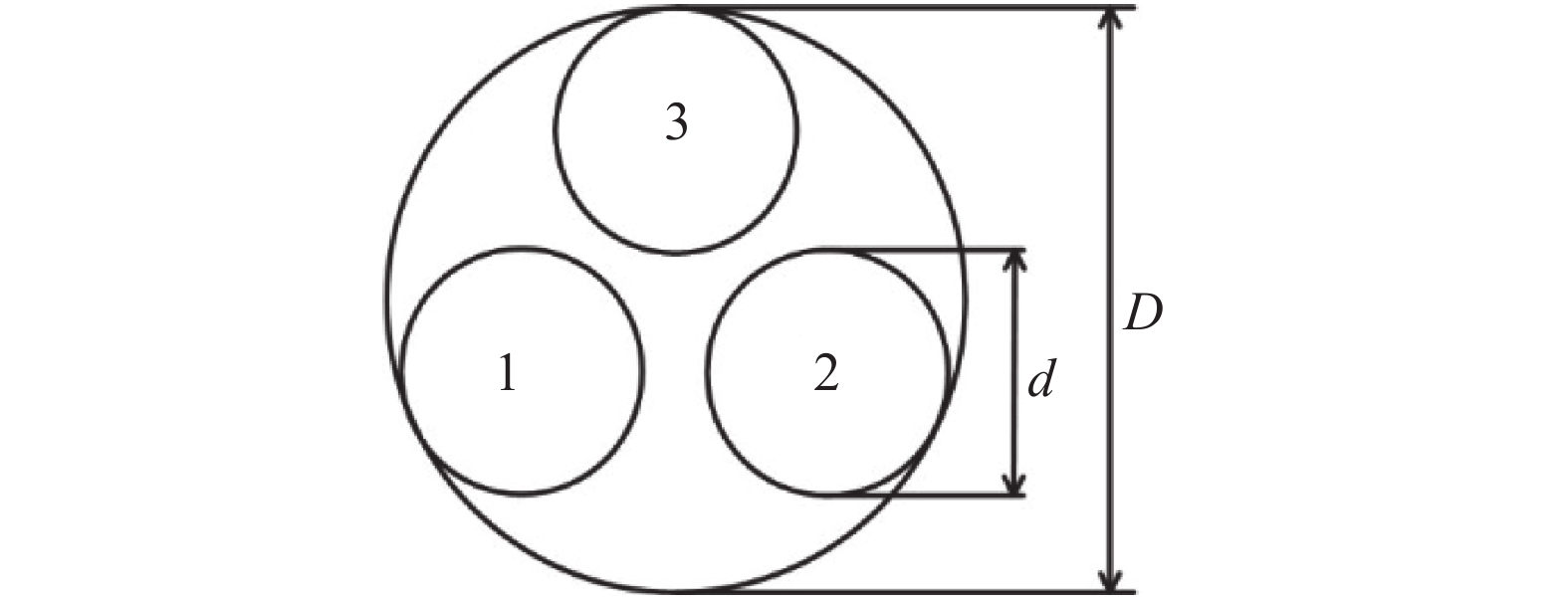
Figure 1. Golay3 system array structure
Golay3光学系统的点扩散函数(point spread function, PSF)为:
式中:
$PS{F_{{\rm{one}}}}\left( {x,y} \right)$ 为单孔径PSF;$d$ 为子孔径直径;$D$ 为外接圆直径;$\lambda $ 为入射光波长;$f$ 为系统焦距。Golay3光学系统的调制传递函数(modulation transfer function, MTF) [11]为:
式中:
$MT{F_{{\rm{one}}}}\left( {{f_x},{f_y}} \right)$ 表示单孔径MTF;$({f_x},{f_y})$ 表示空间频率。由公式(2)可知,当子孔径间存在相位误差时,孔径间的相对位置关系不再对称,导致系统的MTF发生改变,成像质量下降。
子孔径间的相位误差对光学系统成像质量影响非常大,在实验调试阶段必须对其进行严格校正。图2给出了Golay3结构中子孔径3存在活塞误差或倾斜误差时的MTF分布图以及相应的面物体成像。

Figure 2. MTF distribution( (a) Error free; (b) Piston error π; (c) Tilt error 0.012 μrad) and surface object imaging ((d) Error free; (e) Piston error π; (f) Tilt error 0.012 μrad)
由图2可以看出,无误差的多孔径MTF分布呈中心对称分布,中心能量最大,周围对称分布六个旁瓣,这与子孔径的排列方式有关。当最大活塞误差为π时,系统MTF偏移量最大。倾斜误差不改变MTF中心位置,但使得MTF分布地更加杂乱无章。多孔径子光束间存在活塞误差和倾斜误差都会导致成像结果模糊。所以,使用多孔径光学系统观测前必须对子孔径进行调整,以排除系统自身的活塞误差和倾斜误差。
-
湍流是大气的一种运动形式,是一种复杂的现象,在湍流大气中,折射率随时间、空间随机变化。大多数情况下,湍流会充满整个视场空间,但由于大气环境复杂,湍流的尺度变化很大,因此还会存在仅影响视场部分区域的小尺度湍流。局部小尺度湍流虽然没有充满整个视场,但是仍会对目标观察产生干扰。文中重点针对这种外尺度较小的湍流情况进行分析。
实际观测中若多孔径望远系统全视场角为0.2°,观测距离为10 km目标,则子孔径可观测到的视场范围约为350 m。当成像光路中出现近似为团状湍流,湍流外尺度小于子孔径的视场时,则望远系统视场中有一部分近似圆形的区域入射光相位值与其他部分不同发生了畸变。为了分析近似圆形湍流对成像系统的影响,对其进行了简化模型构建,如图3(a)中阴影部分所示。
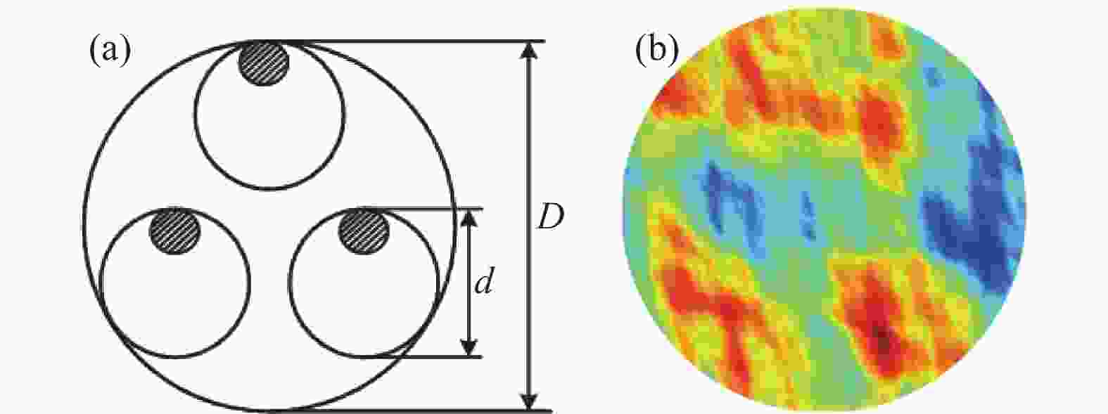
Figure 3. (a) Schematic diagram of similar circular turbulence in the field of view and (b) phase distribution in turbulent region
近似圆形湍流引起的相位差由以下方法计算。根据参考文献[12]使用各向异性大气湍流功率谱
${\varPhi _n}({\kappa _x},{\kappa _y})$ :式中:
${\mu _x}$ 和${\mu _y}$ 分别表示$x$ 和$y$ 方向各向异性分子;$({\kappa _x},{\kappa _y})$ 表示空间频率;$\bar C_n^2$ 表示折射率广义结构常数,单位为${\rm{m} ^{3 - \alpha }}$ ,是表示湍流强度的一个重要参数;$A(\alpha )$ 表示保持其指数结构函数与其功率谱一致性的常数。式中:
$\varGamma (x)$ 表示$\gamma $ 函数;$\alpha $ 表示与高度有关的光谱指数。通过对大气湍流的功率谱进行滤波,再做逆傅里叶变换可以计算出湍流影响的相位值[13-14]分布如图3(b)所示。
随着湍流随机运动,如果空间存在一个分布方向正好垂直于视场的近似长条状湍流,例如对流湍流中山波湍流[15-16],望远系统视场中有一部分近似长条状的区域入射光相位值与其他部分不同,发生了畸变,对其进行简化模型构建,如图4(a)阴影部分所示。

Figure 4. (a) Schematic diagram of similar elongated turbulence in the field of view; (b) Turbulent gas density distribution and (c) phase distribution
文中近似长条状湍流引起的相位差由以下方法计算。对流湍流的分析模型需要结合空气的流体动力学情况来建立,利用Fluent软件计算强风通过山脉产生的山波湍流,得到湍流区域的密度分布,如图4(b)所示,再利用Gladstone-Dale关系:
式中:
$n$ 为折射率;$\;\rho $ 为密度;$K$ 为Gladstone-Dale系数[17]。式中:
$\lambda $ 为入射光波长。计算出湍流区域的折射率场分布,进而可求出光场经过近似长条状湍流的相位分布,如图4(c)所示。
-
近似圆形湍流影响下的系统PSF可表示为:
式中:
${J_1}$ 表示一阶贝塞尔函数;${r_n} = \sqrt {x_n^2 + y_n^2} $ ,$({x_n},{y_n})$ 表示子孔径中心坐标;$d$ 表示子孔径直径;${r_{ln}} = \sqrt {x_{ln}^2 + y_{ln}^2} $ ,$({x_{{l_n}}},{y_l}_{_n})$ 表示近似圆形湍流中心坐标;$\varphi $ 表示湍流影响附加相位差。后文中湍流影响导致的附加相位差都用相位差表示。公式(7)等号右边绝对值内第一、二项分别表示没有湍流影响和有湍流影响的振幅扩散函数,振幅扩散函数模平方为PSF。湍流变化引起的大气折射率起伏导致光波波前畸变,改变望远镜系统视场内相位均匀性,造成光学图像的模糊,影响光学系统PSF,进而恶化系统MTF。
系统的MTF为:
通过改变近似圆形湍流在视场中的不同位置,计算得出湍流位于子孔径边缘对系统成像性能影响最大。并且经过计算发现,当湍流区域直径小于d/6时,系统MTF分布基本不变,即尺度较小的湍流对系统成像影响不大。
经过计算发现,湍流在视场中的位置和尺度大小会影响系统MTF,但其主要的影响规律相同。如图3(a)所示,近似圆形湍流直径为d/3,湍流尺度约为100 m,取湍流层的传输距离为512 m,分析湍流变化对系统成像的影响。
图5给出了近似圆形湍流区域相位变化
$0 \sim 2\pi $ 的MTF分布以及相应的面物体成像和不同相位差的MTF曲线。
Figure 5. Influence of similar circular turbulence on MTF of system ((a) π/2 (3π/2); (b) π) and plane object imaging phase difference ((c) π/2 (3π/2); (d) π; (e) MTF curves with different phase differences)
由图5可知,当近似圆形湍流影响改变,系统MTF中心位置并没有发生移动,随着相位差由0增加到π,MTF畸变程度越来越严重,中心由圆形变成椭圆,椭圆两尖端逐渐分裂开,周围的六个旁瓣范围逐渐缩小。从图5(e)定量分析,以相位差为
$0\pi (2\pi )$ 的MTF曲线为基准,相位差为${\pi / 2}({{3\pi } / 2})$ 和$\pi $ 的MTF分别在归一化空间频率0.16处下降了0.06和0.19,在频率0.45处下降了0.04和0.09,在频率0.69下降了0.034和0.08。另外,当湍流强度为
$\overline C_n^2 = {10^{ - 8}}\;{{\rm{m}}^{3 - \alpha }}$ ,距离入瞳距离分别为h=8、10、15、20 km时,由参考文献[12]可知当湍流强度一定时,湍流导致的相位差值与湍流层高度有关,所以在近似圆形湍流区域构建不同高度的随机相位屏,相位分布的值放入512×512的矩阵中,矩阵中每点的相位差值可表示对应空间位置的相位起伏,以此来研究近似圆形湍流影响下的MTF。便于分析计算出对应随机相位屏的相位均值分别为70.82 π、8.09 π、0.61 π、0.027 π。由图6可知,当高度为8、10、15 km时,MTF的畸变比较明显,中央类似一个椭圆形,周围六个旁瓣位置并没有发生明显变化。当高度为20 km时,圆形湍流对MTF分布的影响不大。

Figure 6. MTF affected by turbulence at different heights ((a) 8 km; (b) 10 km; (c) 15 km; (d) 20 km)
当湍流高度为8 km时改变湍流强度,令
$ {\overline{C}}_{n}^{2}= {\rm{10}}^{\rm{-8}}\rm{ }{\text{、}} $ $ {\rm{ 10}}^{\rm{-13}}\rm{ }{\text{、}}{\rm{ 10}}^{\rm{-15}}\;{\rm{m}}^{3-\alpha }$ ,在近似圆形湍流区域构建不同湍流强度的随机相位屏,并计算出对应随机相位屏的相位均值分别为70.82 π、1.11 π、0.14 π。图7(d)所示MTF曲线为过MTF分布中心且平行于
${f_x}$ 方向的数据,结合随机湍流相位屏均值,可知同一高度湍流强度越小对系统的MTF影响越小。以理想情况的MTF曲线为基准,湍流强度最小的MTF曲线和理想情况相似,而另外两条强度大的MTF曲线,在归一化空间频率0.16、0.45和0.69处都有所下降。强度为${\rm{1}}{{\rm{0}}^{{\rm{ - 13}}}}\;{{\rm{m}}^{3 - \alpha }}$ 和${\rm{1}}{{\rm{0}}^{{\rm{ - 8}}}}\;{{\rm{m}}^{{\rm{3 - }}\alpha }}$ MTF曲线分别在频率0.16处下降0.06和0.09,0.45处下降0.04和0.05,0.69处下降0.03和0.04。
Figure 7. MTF of different intensities of turbulence ((a) 10−8 m3−α; (b) 10−13 m3−α; (c) 10−15 m3−α) and (d) MTF curves of different turbulence intensities
-
近似长条状湍流影响下的系统PSF可表示为:
式中:
$({x_{{l_n}}},{y_l}_{_n})$ 表示近似长条状湍流中心坐标;$b$ 表示近似长条状湍流宽度。公式(9)等号右边绝对值内第一、二项分别表示没有湍流影响和有湍流影响的振幅扩散函数。通过改变近似长条状湍流在视场中的位置,计算得出位于子孔径中心的湍流,能更好地突出对光学系统性能的影响。并且计算发现,湍流区域宽度越窄,对系统MTF分布变化影响越大。
如图4(a)所示,近似长条状湍流宽度为
${d / {10}}$ ,取湍流层的传输距离为512 m,分析湍流变化对系统成像的影响。图8给出了近似长条状湍流区域相位变化$0 \sim 2\pi $ 的MTF分布以及相应的面物体成像和不同相位差的MTF曲线。
Figure 8. Influence of similar elongated turbulence on MTF of system ((a) π/2 (3π/2); (b) π plane object imaging phase difference; (c) π/2 (3π/2); (d) π; (e) MTF curves with different phase differences
由图8可知,当近似长条状湍流引起相位差逐渐改变时,MTF的中心区域没有移动,但中心区域范围减小,中心亮斑和旁瓣产生线条状的畸变,除中心处外,线条处的能量最大。图8(c)、(d)为面物体成像,相比近似圆形湍流,近似长条状湍流对系统的成像质量影响更加严重。从图8(e)定量分析,以相位差
$0\pi $ $ (2\pi )$ 为基准,相位差${\pi / 2}({{3\pi } / 2})$ 的MTF在归一化空间频率0.17处下降0.537,0.39处(MTF为0)下降0.28,0.69处下降0.144;相位差π的MTF畸变程度非常大,MTF值在频率0.078、0.21、0.34、0.48、0.63和0.75处下降为0,同时MTF除了在中央零频有极大值,分别在频率0.14、0.27、0.42、0.54、0.68和0.81处有极大值,分别为0.21、0.40、0.14、0.33、0.028和0.044。由此可知,近似长条状湍流对系统的MTF影响非常明显。另外,利用Fluent软件计算光波长550 nm、风速分别为10、20、30 m/s的强风通过山脉产生的山波湍流,再通过计算得到近似长条状湍流区域的相位差分布,以此来研究近似长条状湍流对系统MTF的影响。便于分析计算出不同风速湍流对应相位差的相位均值分别为9.39 π、9.54 π、9.63 π。图9给出不同风速影响下的MTF分布和MTF曲线。

Figure 9. MTF affected by different wind speeds ((a) 10 m/s; (b) 20 m/s; (c) 30 m/s) and (d) MTF curves of different wind speed influence
由图9结合Fluent仿真,对流湍流的密度分布在两种气流的交界处变化梯度非常大,进而不同风速下近似长条状湍流,除了交界处相位差有明显差异,其余湍流域相位差相差不大,因此MTF只在较小空间频率处有明显的差异。由图9(d)MTF曲线定量分析,以理想情况的MTF为基准,风速为10、20、30 m/s的MTF曲线在归一化空间频率0.16处分别下降0.23、0.24、0.25,在频率0.42处均下降约0.089,在频率0.69处均下降0.046。同时三条MTF曲线除在中央零频有极大值,分别在频率0.25和0.50处出现极大值,分别为0.37和0.32。
由图3和图4的近似湍流示意图分析,成像系统实际上是一个低通滤波器,根据空域与频域的对应关系可知,通光孔径不同空间位置将对应不同的空间频率范围。在近似圆形和近似长条状湍流面积占成像系统视场比相差不大情况下,近似圆形湍流只对目标图像某一频段产生影响,近似长条状湍流由于贯穿了整个孔径,因此对目标图像低、中、高频整个频段产生影响。同时由图5和图8分析,附加相位差相同时,近似长条状湍流影响的MTF变化更加明显。由图7和图9MTF曲线分析,除去多孔径系统附加相位差2 π周期效应,近似圆形湍流强度为
${\rm{1}}{{\rm{0}}^{{\rm{ - 8}}}}\; {{\rm{m}}^{{\rm{3 - }}\alpha }}$ 的有效均值相位差为0.82 π,近似长条状湍流风速为20 m/s的有效相位差为0.54 π,虽然近似圆形湍流的有效相位差较大,但是近似长条状湍流对MTF的影响更显著。 -
为了分析较小尺度湍流对多孔径光学系统的影响,对多孔径望远系统设计使用提供参考,建立了一个Golay3结构的湍流成像分析模型,分别推导了近似圆形湍流和近似长条状湍流影响下的光学系统PSF,并构建了光场相位计算模型,计算得到了两种稳态湍流影响下的成像系统MTF分布。当光路中存在湍流将导致光学系统成像质量下降。近似圆形湍流中,计算了不同高度和不同强度的湍流带来的影响,当高度大于或等于20 km时,湍流引起的相位差非常小,对系统MTF影响不大。此外,同一高度湍流强度越小,产生的相位差越小,对系统的MTF影响越小。对近似长条状湍流,计算了不同风速湍流带来的影响,当风速变化时,对MTF的影响并未发生明显改变。近似圆形湍流对成像目标某一频段产生影响,近似长条状湍流对成像目标低、中、高频整个频段产生影响。在较强湍流下,近似圆形湍流影响的MTF在归一化空间频率0.16、0.45、0.69处分别下降0.08、0.05、0.03左右。在较大风速下,近似长条状湍流影响的MTF在频率0.16、0.42、0.69处分别下降0.25、0.09、0.05左右。相比而言,后者对系统成像影响非常大,使得MTF分布产生明显条状畸变。
Influence of turbulence on imaging characteristics of multi-aperture optical system
doi: 10.3788/IRLA20210189
- Received Date: 2021-03-19
- Rev Recd Date: 2021-05-20
- Publish Date: 2021-12-31
-
Key words:
- turbulence changes /
- multi-aperture imaging /
- point spread function /
- modulation transfer function
Abstract: In order to study the influence of atmospheric turbulence on the imaging quality of multi-aperture optical system, a theoretical analysis model was established for the Golay3 structure. The expression of point spread function (PSF) and modulation transfer function (MTF) of this structure were derived. To discuss the influence of similar circular and elongated turbulence structures on the imaging characteristics, the MTF under two turbulence conditions were calculated and compared, and the phase calculation models were constructed. The results show that when there is presence of turbulence in the optical path, the image quality of the system will decrease. As for similar circular turbulence, the smaller the intensity of turbulence is, the less the impact on the MTF is. Specially, the MTF affected by turbulence of different intensities decreases by about 0.05 at the normalized spatial frequencies of 0.16, 0.45, and 0.69. As for similar elongated turbulence, the smaller turbulent wind speed is, the less the impact on the MTF is. The MTF affected by turbulence of different wind speeds decreases by about 0.25, 0.09, and 0.05 at the spatial frequencies of 0.16, 0.42, and 0.69, respectively. The comparison of the influence of the two turbulences on the system shows that the similar elongated turbulence has a more obvious influence on the MTF.


 DownLoad: