


HTML
-
随着对地观测技术的快速发展,对空间相机的分辨率要求也越来越高。由于光学系统的角分辨率与通光口径成反比,因此增大空间相机的口径是提高分辨率最直接最有效的手段。非球面反射镜能有效地校正多种像差,改善像质,并减少系统所需光学元件的数量,减小系统外形尺寸,近年来被广泛用于大口径反射镜系统[1-3]。
主反射镜通常是空间遥感相机系统装调的基准,主镜光轴加工偏差或装调位置度偏差不仅会带来其他光学元件进行较大位置的调整,还会导致系统成像焦面偏离设计位置,影响在轨成像效果。因此在加工过程中必须严格控制主反射镜光轴偏心,在装调过程必须将主镜光轴装调至与结构基准一致。反射镜偏心测量常用的方法有:中心偏测量仪直接测试法、接触法和干涉法。用中心偏测量仪直接测量反射镜偏心时测量精度较高,但是不能测量中心区域有孔的反射镜。接触法是使用三坐标仪或者激光跟踪仪,在机械基准坐标系下对镜面进行扫描,接触法常用于反射镜加工初期偏心测量,在镜面完成精加工及装调阶段,接触法可能会损坏镜面。干涉法是在反射镜面形测试的基础上,利用光电经纬仪和激光跟踪仪等设备测量反射镜光轴与机械轴的偏差。
基于大口径凹椭球面反射镜面形参数,给出用平晶进行球差补偿的结果,并对光学元件灵敏度进行分析,通过实验室测量主反射镜的偏心。此方法已成功应用于多个在轨型号,并取得良好效果。
-
用y表示非球面的旋转对称轴,x表示入射光学在非球面上的高度,则轴对称非球面的子午截面曲线方程可以写成以下形式[4]:
式中:c为顶点曲率(
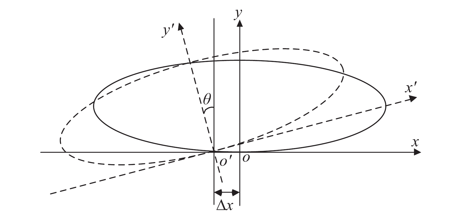
$c = 1/\mathop R\limits^o $ );K为二次曲线常数;$ d、 $ $ e、\cdots $ 为系数。对于二次曲线,比如图1所示的椭球面,曲线方程表达式如下:如图1所示,
$oy$ 轴为椭球面几何旋转对称轴,$o'y'$ 为椭球面光轴,由于加工偏差,椭球面光轴与几何旋转对称轴并不重合,既存在角量偏心$\theta $ (以下简称角偏心)又存在线量偏心$\Delta x$ (以下简称线偏心)[5-6]。
Figure 1. Eccentricity of the ellipsoid
-
全反射式光学系统光学元件失调主要引入初级像差,不会产生新的像差类型。失调共轴三反系统初级像差的Zernike标量表达式如下[7]:
式中:
${W_j}(\rho ,\phi )$ 为$j$ 视场波像差;${Z_i}(\rho ,\phi )$ 为Zernike多项式;$C_i^j$ 为多项式$j$ 视场拟合系数。表1给出了Zernike圆域多项式像散、彗差和球差表达式,表中θ为极角,$\rho $ 为半径[8-9]。Term # Polynominal expression Meaning Brief exp. 5 ${\rho ^2}\cos 2\theta $ Astigmatism 0° or 90° Z5 6 ${\rho ^2}\sin 2\theta $ Astigmatism ±45° Z6 7 $(3{\rho ^2} - 2)\rho \cos \theta $ X coma and tilt Z7 8 $(3{\rho ^2} - 2)\rho \sin \theta $ Y coma and tilt Z8 9 $6{\rho ^4} - 6{\rho ^2} + 1$ Spherical and focus Z9 Table 1. Zernike polynominal expressions of circular domain
-
光学系统中光学元件的失调会引入像差,将初级像差作为校正对象,则校正对象与失调量之间为非线性关系,利用多元泰勒公式将非线性方程组转化为下列线性方程组[10-14]:
A为灵敏度矩阵:
ΔX为系统中各光学元件的失调量,包括各坐标轴的平移量、转动量。ΔF为光学系统各校正对象实测值与设计值之差,灵敏度矩阵A为校正对象与调整变量的差商。公式(4)的最小二乘解为:
若矩阵非奇异,则方程组的解为:
-
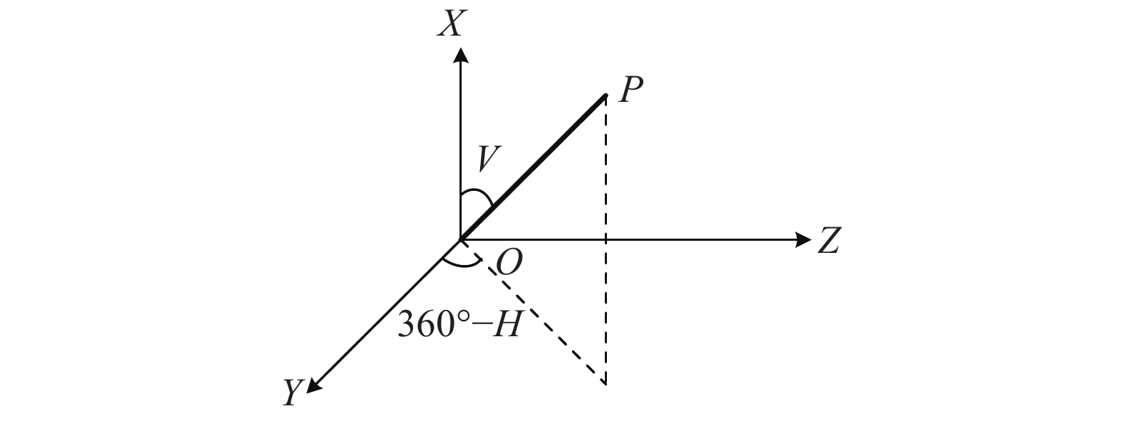
以经纬仪的(0°,90°),(270°,90°)方向分别为+Y和+Z轴建立右手正交坐标系,称为测量坐标系,记为∑0。坐标系∑0的X轴正方向竖直向上,此时Y轴正方向为经纬仪的零位。假设经纬仪自准空间某方向P,对应的水平角和竖直角读数分别为H和V,如图2所示,P点的空间向量分量在测量坐标系∑0中表示为[15]:

Figure 2. Establishing the measuring coordinate system ∑0
1.1. 轴对称非球面偏心


1.2. 光学系统像差计算


1.3. 灵敏度矩阵
1.4. 经纬仪测量坐标系
-
平行光经过椭球面反射镜后成像,会存在较大正球差,计算公式如下:
式中:N0为球差;
$u'$ 为理想像面处的光线反射角。由于汇聚光线经过平晶后正好产生负球差,在此系统中选用平晶来补偿椭球面的正球差。平晶球差计算公式为:
测试主镜为1070 mm口径椭球面反射镜,反射镜采用ULE蜂窝结构,如图3所示。采用国产K9平晶玻璃对主镜球差进行补偿,测试光路如图4所示,参数如表2所示。

Figure 3. Primary mirror under test

Figure 4. Optical model of test
Optical element Vertex radius of curvature/mm K Mirror spacing or thickness/mm Effective light aperture/mm Materials Primary mirror −3042.54 −0.9727 −1430.00 1070.00 ULE Optical flat ∞ − −28.00 66.45 K9 ∞ − −78.78 53.38 Table 2. Design results of the optical system
-
光学系统只有椭球面主镜和平晶玻璃两个光学件,表3分析了系统像差,可以看出利用厚度为28 mm的K9平晶玻璃,可以将主镜球差完全补偿,系统理论像差为零。
Zernike coefficient (λ) RMS(λ) Interferogram Z5 Z6 Z7 Z8 Z9 Before spherical aberration compensation 0 0 0 0 5.3 2.4 
After the spherical aberration is compensated 0 0 0 0 0 0 
Table 3. Aberration of the system(λ=632.8 nm)
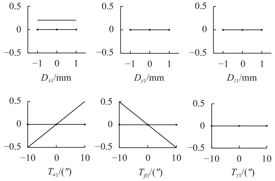
在进行系统调整时通常使用平面镜建立自准直光路,以平面镜为基准调整主镜和平晶的空间位置。用D和T表示光学件的平移失调和空间角失调,主镜六个空间调整变量分别为
$ {D}_{x1}、{D}_{y1}、{D}_{{\textit{z}}1}、{T}_{\alpha 1}、{T}_{\beta 1} $ $ 和{T}_{\gamma 1}$ ,平晶六个空间调整变量分别为$ {D}_{x2}、{D}_{y2}、 {D}_{{\textit{z}}2}、 $ $ {T}_{\alpha 2}、{T}_{\beta 2}和{T}_{\gamma 2}$ 。图5和图6分别给出了主镜和平晶的失调量与像散、彗差和球差的关系,可以看出,平移、镜间距以及绕光轴的旋转不影响系统像差,俯仰和旋转失调只会引入彗差,并且失调量与彗差成线性关系。
Figure 5. Relationship between misalignment variables and aberrations of the primary mirror
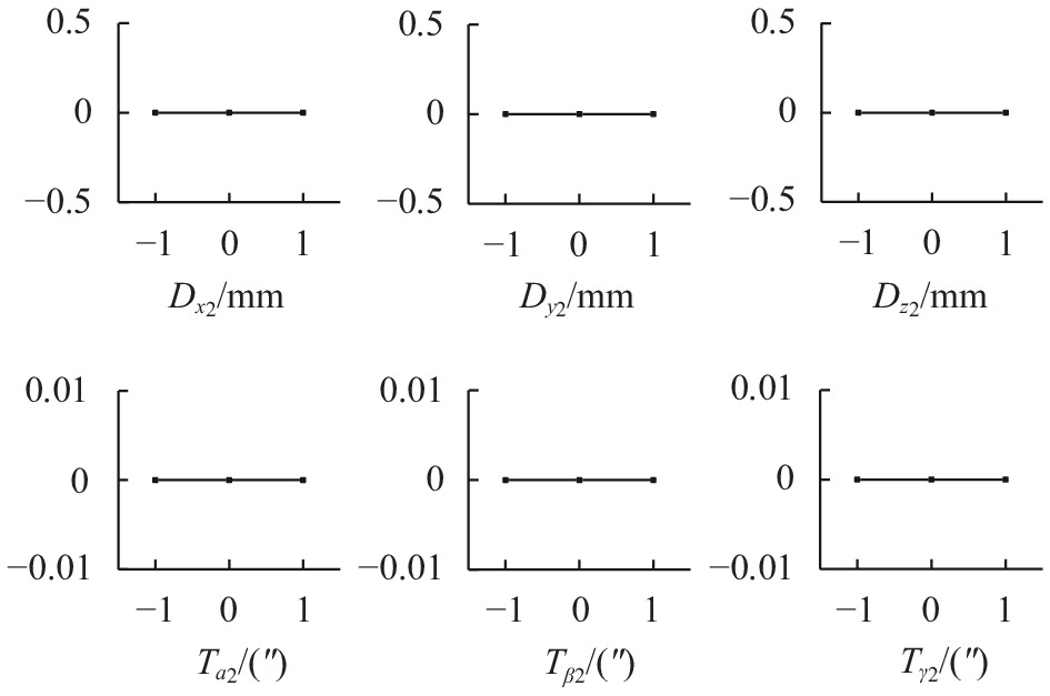
Figure 6. Relationship between misalignment variables and aberrations of the flat crystal
通过计算图5和图6各曲线的斜率,即可得到次镜和三镜的灵敏度矩阵。由于系统是旋转对称的,所以等量的俯仰失调和旋转失调引入的彗差大小相同,表4给出了主镜和平晶的俯仰(
${T_\alpha }$ )灵敏度矩阵。可以看出,主镜俯仰或旋转失调会引入较大的彗差,主镜和平晶失调灵敏度为149:2。Z5 Z6 Z7 Z8 Z9 ${T_{\alpha 1}}$ 0 0 0 149 0 ${T_{\alpha 2}}$ 0 0 0 2 0 Table 4. Sensitivity matrix
-
(1)测试系统搭建与调整
如图7所示,利用Φ1600 mm平面镜建立自准直测量光路。利用经纬仪通过主镜中心孔同时看到平面镜和平晶的自准直像,调整平晶俯仰和倾斜使平面镜和平晶的自准直像重合,即主镜法线与平晶法线平行。调整主镜俯仰和倾斜,直至4D干涉仪测得的系统彗差项
${Z_7}$ 和${Z_8}$ 小于0.05λ。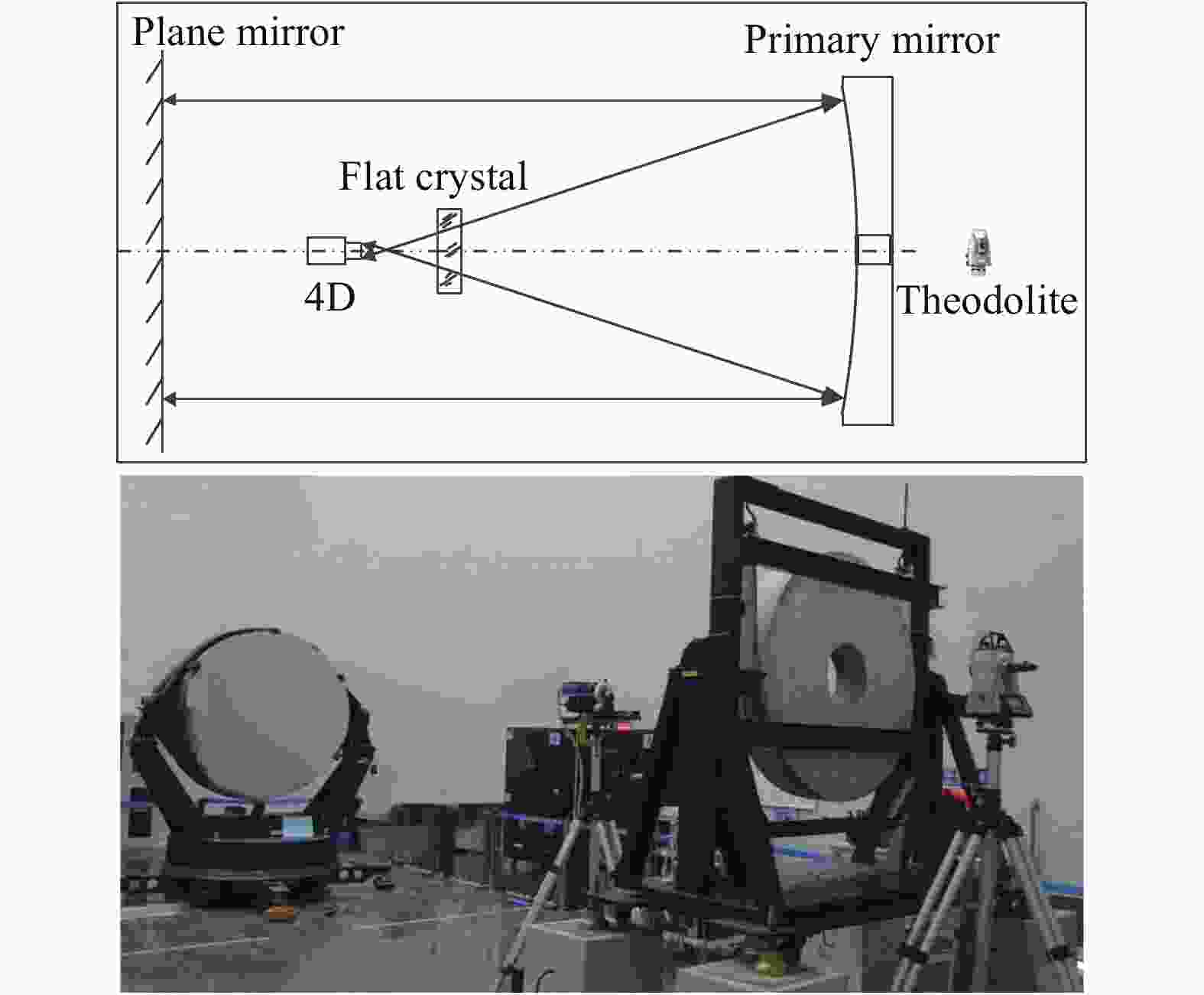
Figure 7. Light path of the test
表5给出了测试结果,系统像散和彗差均小于0.05λ。干涉仪及其支撑机构在光路里有比较大的遮拦,对系统像差的测试有一定影响,如果要测试主镜的真实RMS值,需要用补偿检验法。
Zernike coefficient(λ) RMS(λ) Z5 Z6 Z7 Z8 Z9 0.048 −0.02 0.00 −0.02 0.03 0.04 Fringe pattern Interference pattern 

Table 5. System aberration (λ=632.8 nm)
(2)主镜角偏心测试
在完成系统调整后,平面镜法线方向即为主镜光轴方向。利用经纬仪自准主镜背后抛光面,同时通过主镜中心孔自准平面镜,平面镜法线方向与主镜背面法线方向的偏差即为主镜光轴的角偏心,测试结果如表6所示。
Normal of a
plane mirrorNormal of primary
mirror backSpace angle/(°) (0, 90.00321) (0.00125, 90.01324) Table 6. Test result of the angle
根据公式(7),平面镜法线和主镜背面法线在经纬仪坐标系
${\Sigma _0}$ 下的单位矢量分别为:$ \stackrel{\rightharpoonup }{{S}_{{\text{平}}}}$ 和$ \stackrel{\rightharpoonup }{{S}_{{\text{主}}}}$ 点乘即为平面镜法线方向与主镜背面法线方向的夹角余弦,从而计算得到平面镜法线方向与主镜背面法线方向的夹角为:(3)主镜线偏心测试
如图8所示,将激光跟踪仪靶球1放置在系统汇聚点附近,调整靶球位置,使干涉仪出射光线经过靶球后自准直,此时靶球中心即为经过平晶补偿后的主镜焦点位置(以下简称主镜焦点位置),用激光跟踪仪器测量靶球位置并记录。将靶球2放在主镜侧面不同位置,用激光跟踪仪测量靶球所在位置,从而得到主镜机械轴,主镜焦点到机械轴的距离即为主镜线偏心。经过测量,主镜线偏心为0.53 mm。

Figure 8. Test of the line eccentricity
2.1. 光学设计结果


2.2. 光学系统仿真分析


2.3. 实验室测量


-
主镜角偏心测量误差主要由光学件失调和经纬仪测量引入,主镜线偏心测量误差主要由光学件失调和激光跟踪仪测量引起。
-
由2.2节可以看出,在自准直光路里,主镜和平晶平移不会引起像差变化,因此对主镜偏心无影响。主镜倾斜或俯仰1″引入的彗差变化为0.04λ(λ=632.8nm),正好是干涉仪测试系统比较容易识别的变化量。经纬仪测量精度为±0.5″,平晶与平面镜平行性可以控制在1″以内,平晶倾斜或俯仰1″引入的彗差变化为零。光学件失调引起的主镜角偏心和线偏心测量误差分别为
${\sigma _{D1}} = 0$ 、${\sigma _{\theta 1}}$ 约为±1″。 -
在主镜角偏心测试时使用经纬仪进行了两次自准直测试,一次是自准直平面镜,另一次是自准直主镜背面,两次测试误差主要取决于经纬仪测量精度
${\sigma }_{\theta 2}={\sigma }_{\theta 3}=\rm{±}0.5$ ″。 -
激光跟踪仪测量精度为±(15+6)μm/m,在进行主镜线偏心测量时,主要进行了两个过程的测量,一是测量主镜焦点位置,二是测量主镜圆柱面来拟合主镜机械轴,分别为
${\sigma _{{D2}}}$ 约±0.02 mm,${\sigma _{{D3}}}$ 约±0.02 mm。 -
主镜角偏心测量误差:
主镜线偏心测量误差:
通过测量误差分析可知,主镜角偏心测量误差约为1.2″,线偏心测量误差为0.028 mm。大口径主镜在加工时角偏心和线偏心一般可以控制在30″以内和0.5 mm以内,在进行光机系统装调通过调整主镜安装位置及角度可以使主镜角偏心和线偏心控制在10″以内和0.05 mm以内。空间相机在结构设计时,都会给各光学件及焦面留有安装调整量。因此,大口径凹椭球面反射镜光轴偏心测量方法可以满足大部分大口径反射镜加工和装调过程中偏心测量的需要。
3.1.
光学件失调引起的误差${\sigma _{{D1}}}$ 和${\sigma _{\theta 1}}$


3.2.
经纬仪测试引起的误差${\sigma _{\theta 2}}$ 和${\sigma _{\theta 3}}$


3.3.
激光跟踪仪测试引起的误差${\sigma _{{D2}}}$ 和${\sigma _{{D3}}}$


3.4. 误差合成
-
基于波前检测的大口径凹椭球面反射镜光轴偏心测量,不仅可以用于大口径凹椭球面反射镜光轴偏心测量,还可以用于中小口径凹椭球面反射镜光轴偏心测量。基于仿真分析结果,搭建了反射镜偏心测试系统,对遥感相机的主镜进行了偏心测量,主镜角偏心为29″,线偏心0.53 mm,在相机装调过程中通过精修主镜支撑结构使光轴与结构基准一致。通过误差分析,角偏心测量误差约为1.2″,线偏心测量误差为0.028 mm,可以满足大部分大口径反射镜偏心测量需求。在加工过程中通过偏心测量为后期加工修正提供依据,使凹椭球面反射镜光轴偏心误差更小。在装调过程中通过偏心测量,精修主镜支撑结构使主镜光轴与相机主体结构基准一致。基于波前探测的大口径凹椭球面反射镜光轴偏心测量方法已应用于多个航天遥感相机的研制中,取得了良好效果。

 DownLoad: