


-
近年来,现代医疗技术朝着微创和局部化治疗发展,其中最为广泛应用的微创手术是经皮穿刺介入手术。经皮穿刺介入手术是指在诸如X-射线、电子计算机断层扫描(Computed Tomography, CT)、磁共振成像(Magnetic Resonance Imaging, MRI)、超声成像等医学影像[1-3]的引导下将医疗器械精确的植入到病灶中并进行组织提取或治疗的一种典型微创手术。因其造成的创口小、疼痛小、术后恢复快,受到了国内外研究学者的广泛关注。在经皮穿刺介入手术治疗过程中,探针是最基础的微创手术医疗器械。大量的手术过程均要求探针准确穿刺到特定位置。高精度的形状传感方法是提升经皮穿刺介入手术成功率的关键。
在先前的研究中,操控探针进入到软组织器官过程中,通过使用例如X-射线、CT、MRI、超声成像等医学影像技术来显示探针的形状。但这些方法具有各自不同的缺点:超声成像虽然可以反馈实时形状信息,但组织对比度较低;MRI速度较慢,无法满足实时反馈的需求;CT扫描会对患者产生大剂量的辐射。且经皮穿刺介入手术探针的控制主要依赖于医生的操作经验,对医生专业技术水平要求极高[4]。正是由于传统的传感方法存在若干缺点,基于光传感原理的光纤传感作为一种柔性微型器件测量方法受到国内外学者的广泛关注[5]。
基于光纤传感的柔性医疗器械测量成为微创手术精密测量的发展方向[6-12],为经皮穿刺介入手术探针的精准形状传感提供了新的思路和契机。Tian等基于马赫-曾德尔干涉仪和光纤传感原理设计了一种曲率传感器,该传感器可以对弯曲平面方向和弯曲转角进行测量[13]。杨等基于马赫-曾德尔干涉仪设计了光纤曲率传感器,通过在光子晶体光纤上刻写光纤光栅,形成测量曲率和温度的传感器[14]。虽然基于马赫-曾德尔干涉仪的传感器具有较好的灵敏度,但由于其结构复杂、体积大限制了此类传感器在微创手术中的应用。刘浩与Farvardin等为骨质疏松手术的治疗研制了光纤形状传感器,将与镍钛丝粘贴的两根光纤放置在软体机器人两侧,通过改变形变中性层的位置增大光纤的检测范围[15]。Xu等将光纤传感器螺旋缠绕到柔性镍钛合金手术操作器中测量其形状参数,通过建立的操作器非线性的力-曲率-应变传感模型,可以实现柔性镍钛合金操作器曲率、扭转角和力的测量[16]。但是此类传感器只适用于外科软体操作器上,不能满足介入手术的临床应用需求。美国哈佛大学Yong-Lae Park等人首次利用兼容MRI的光纤布拉格光栅(Fiber Bragg Grating,FBG)传感器对探针进行实时形状检测[17]。HenKen等人利用嵌入三根光纤光栅的探针对肝肿瘤细胞进行检测[18],并证明了该方法的有效性,实验结果表明平均误差为0.89 mm,精度较低,限制了该传感器的实际应用。Roesrhius等人将光纤光栅粘贴到探针表面,通过对光纤芯位置的校正和使用基于单元法提升探针形状重构精度[19]。Kirsten等人分析了FBG的数量、位置对于形状重构精度的影响[20]。尽管上述方法对于减小形状测量误差有显著作用,但忽略了由于介入探针受力不均、每个FBG不同位置所受应变不同、制造工艺有缺陷等因素所导致的多个光纤光栅传感器应变灵敏度差异对形状测量精度的影响。目前对于多个光纤光栅传感器应变灵敏度差异的相关研究鲜有报道,而应变灵敏度是形状传感算法的基础,所以研究每个光纤光栅传感器的应变灵敏度至关重要。
针对上述问题,文中提出一种引入应变灵敏度矩阵的光纤光栅传感阵列介入探针形状测量方法。首先基于光纤光栅传感理论,分析了植入在探针中光纤光栅波长漂移量与其应变的关系,同时引入了应变灵敏度矩阵,研究了光纤光栅中心波长漂移量与其弯曲曲率的关系。然后推导了探针的局部单元几何参数关系和三维坐标转换方程,建立了基于光纤光栅的探针形状测量模型。最后通过实验对比分析了引入应变灵敏度矩阵前后形状测量的误差,实验结果表明引入光纤光栅应变灵敏度矩阵可有效提升介入探针的测量精度。
-
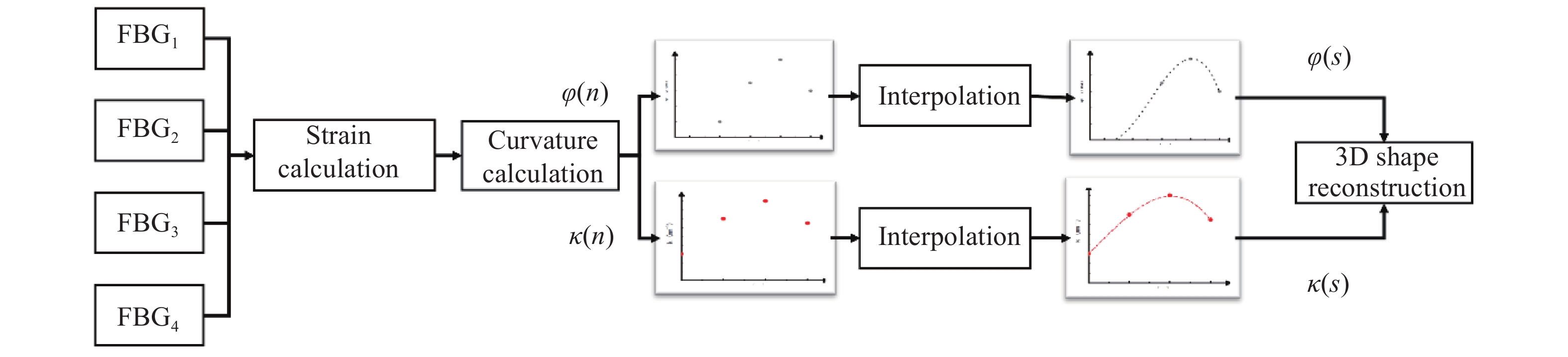
介入手术探针三维形状传感算法流程图如图1所示。首先通过光纤光栅传感器测量应变,由应变求得各个测量点的曲率和弯曲角度,根据曲率和弯曲角度重构出探针形状。
Figure 1. Flowchart of shape reconstruction algorithm
文中所采用的传感器为光纤布拉格光栅,根据模式耦合理论,当宽带光在FBG种传输时,满足布拉格波长条件的光被反射,反射光的中心波长
$ {\lambda }_{B} $ 满足以下的条件:式中:
$ {\lambda }_{B} $ 为布拉格光纤光栅的中心波长;$ {n}_{eff} $ 为有效折射率;${\varLambda }$ 为光栅周期,如图2所示。对公式(1)进行全微分得:
Figure 2. Schematic of a FBG sensor
不考虑波导效应,即不考虑光线轴向变形对折射率得影响,布拉格波长漂移量
$ {\mathrm{\Delta }\lambda }_{B} $ 与受到的应变${\rm d}{\varepsilon }_{x}$ 和温度变化$ \mathrm{d}T $ 的关系如公式(3):式中:
${p}_{e}$ 为光弹性系数,光弹性被定义为反射波长随轴向应变而发生的变化,与FBG自身特性有关;S是光纤的温度灵敏度系数。考虑到微创手术环境温度变化较小,所以文中忽略温度变化即$ \mathrm{d}T $ =0。则当光纤光栅被拉伸或压缩时,只与受到轴向应变${\rm d}{\varepsilon }_{x}$ 有关。由于每个FBG应变灵敏度各不相同,会对形状测量结果产生影响,因此引入应变灵敏度矩阵K:式中:Km−n代表第m根光纤,第n个光栅。此时每个FBG所受应变
$ \varepsilon $ 与其中心波长漂移量$ {\mathrm{\Delta }\lambda }_{B} $ 的关系为:以嵌入三根光纤得探针形变为例,忽略扭转的影响,光纤发生纯弯曲,纯弯曲形变如图3(a)所示,则光纤的应变与旁轴纤芯到中性轴之间距离的关系为:

Figure 3. (a) Pure bending model and (b) cross section of the sensing point
式中:k为曲率;ρ为曲率半径;δ为旁轴纤芯到中性轴的距离。联立公式(4)、(5)可推导出波长漂移量与曲率的关系:
-
选取探针中的一个传感点截面图为例,如图3(b)所示,记由中心轴线指向纤芯c的方向为z轴正方向,该检测点指向下个检测点的方向为x轴正方向,右手螺旋准则判断y轴正方向。纤芯a与中性轴的夹角为φ,可以用来表示曲率的弯曲方向;
旁轴纤芯(a, b, c)之间的夹角(
$\; {\beta }_{\rm a}$ ,$\; {\beta }_{\rm b}$ ,$\;{\beta }_{\rm c}$ )均为120°;芯间距(${r}_{\rm a}$ ,${r}_{\rm b}$ ,${r}_{\rm c}$ )由探针结构设计图可知;在任意位置的三个纤芯的应变方程组可以表示为:式中:
${r}_{\rm a}$ =${r}_{\rm b}$ =${r}_{\rm c}$ ,所以芯间距用r表示。应变偏差$ {\varepsilon }_{0} $ 通常由温度变化或外力作用所引起,每根纤芯的$ {\varepsilon }_{0} $ 均一样。通过解方程组(8)可以确定未知参数(曲率k及其夹角$ \varphi $ )。 -
根据微分几何理论,引进运动坐标系概念,建立运动坐标系(见图4) 假设第i点曲率大小为
$ {k}_{i} $ , 且$ {k}_{i} $ ≠0时,曲率半径大小为$ {\rho }_{i} $ ,曲率方向与Xi 轴正方向夹角为$ {\varphi }_{i} $ ,已知每两个点之间弧线段长度为ds,每段圆弧对应的圆心角可以表示为:
Figure 4. The moving coordinate system of the needle
记i+1点在Oi坐标系下的坐标为{
$ {x}_{i+1} $ ,$ {y}_{i+1} $ ,${{\textit{z}}}_{i+1}$ },可以推算出i+1点坐标的表达式:假设ki=0时,ρi为无穷大,则i+1点在Oi坐标系下的坐标为:
假设
$ \left\{{X}_{i+1},{Y}_{i+1},{Z}_{i+1}\right\} $ 为在Oi+1坐标系下的坐标 (见图5),则第i点从Oi坐标系转换到Oi+1坐标系的变换矩阵为: 由此得到Oi坐标系转换到Oi+1坐标系的表达式为:
其中,
由于第一个检测点O1与基准点O0重合,因此O0节点坐标系与O1节点坐标系之间的转换矩阵为单位矩阵,即对应的t1为单位矩阵。因此,从Oi+1坐标系转换到Oi坐标系的表达式为:
从Oi节点坐标系转换到O0坐标系的递推矩阵为Ti,即:
由此可以推导出Ti与ti+1的关系为:
式中:当i=1时,T1为单位矩阵。
因此,空间中所有节点在O0节点坐标系下的坐标为:
因此,通过公式(25)将i=1,2,···,n个离散空间坐标系中曲线段的点坐标依次换算到O0节点坐标系中,完成探针形状测量。
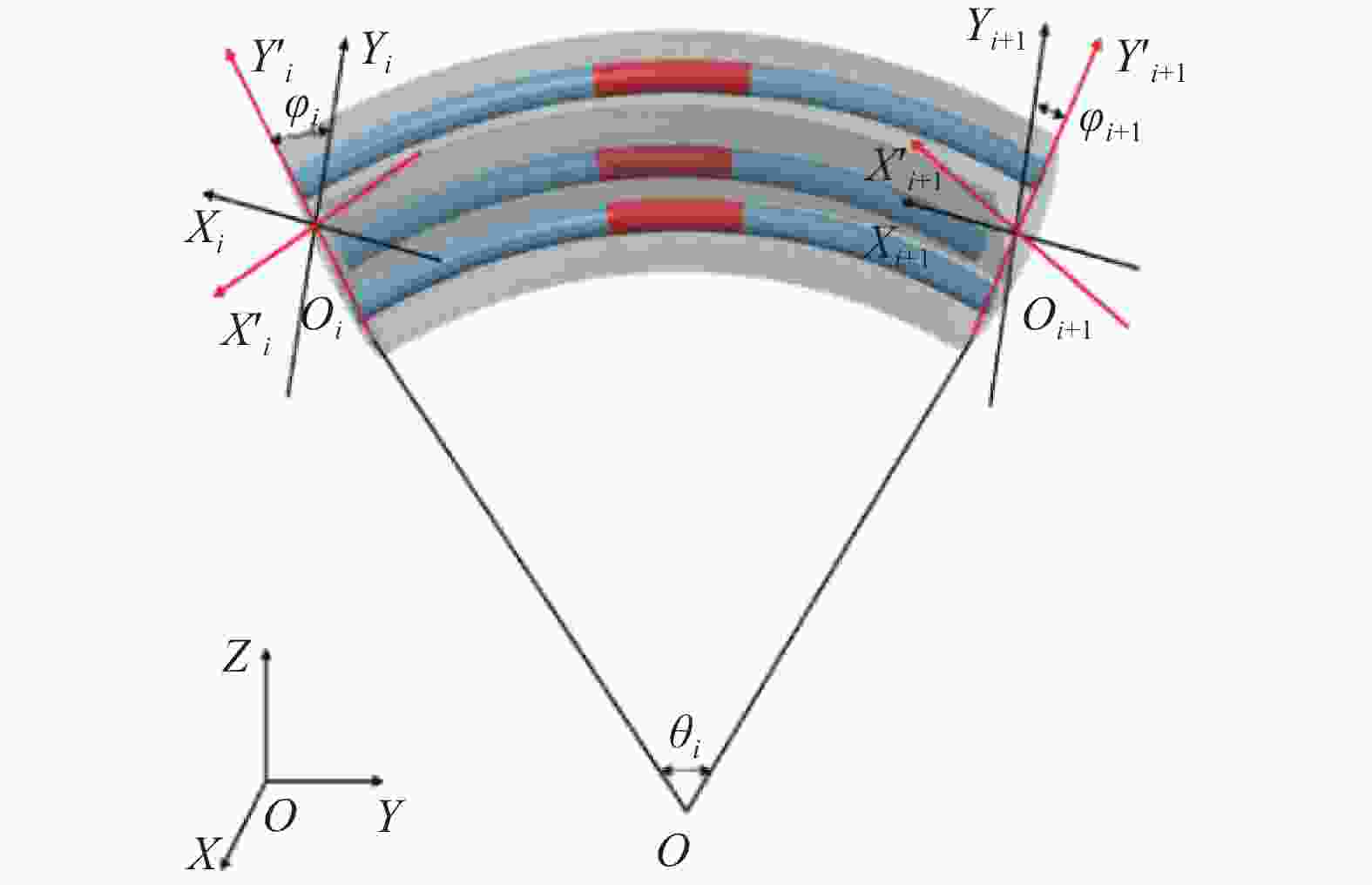
Figure 5. Coordinate conversion
-
文中的FBG采用紫外光刻写掩模版法,利用基于波长248 nm的紫外光激光器与相位掩模板相结合,在经载氢后的Corning SMF-28光纤上刻写栅区为6 mm的FBG。根据目前穿刺术中较为常见探针的特点,文中的探针选用直径为1 mm的镍钛记忆合金丝,同时于镍钛合金针(杨氏模量E=83 GPa)的外侧布设三根光纤光栅(ϕ250 µm)且互相成120°排列。每根光纤上以40 mm为间隔均匀分布四个栅区,最后一个栅区(光栅点1)距离针尖20 mm,如图6所示。使用按照1∶1混合的3M公司的DP2216环氧胶将光纤光栅胶封于镍钛合金针中,为防止FBG发生应力集中现象,需要将搅拌均匀的DP2216环氧胶静置至气泡完全消失。
-
应变灵敏度标定系统如图7所示,主要由两台手动位移平台组成,两台位移平台间距230 mm,位移平台采用微纳光科公司的WN103TM13H位移台,行程13 mm,最小刻度10 µm。光纤传感形状测量系统如图8所示,主要包括运动控制系统、光纤传感系统、探针模型和计算机等。通过固定探针一端,利用运动控制系统使探针实现不同方向、不同偏移量的弯曲。运动控制系统主要由运动控制器和电动多维位移台组成:运动控制器采用微纳光科仪器公司WNMC400控制器,多维位移台采用微纳光科公司WN303ZA位移台。光纤传感系统(见图8)主要由ASE光源、光谱仪、耦合器等组成。ASE光源选用接口类型为FC/APC的Lightpromotech M1043-1,其输出光谱为1529~1605 nm,功率为13 dBm,光平坦度小于2 dB。光谱仪采用波长为1200~2400 nm的YOKOGAWA AQ6375,其功率为−70~+20 dBm,快速测量时间为0.2 s,跨度为100 nm。光纤传感系统的反射信号被传输到光谱仪中并被转换成数字信号。利用上位机中Matlab软件对信号进行寻峰处理和差值运算,利用形状重构算法完成对探针形状参数的计算。

Figure 6. Integrated FBG design of needle for percutaneous intervention

Figure 7. FBG strain sensitivity calibration system

Figure 8. Needle optical fiber sensing shape measurement system. (a) PC; (b) Interrogator; (c) Optical fiber; (d) Needle; (e) Location hole;(f) Motion control; (g) Six axis displacement
-
首先对光纤封装前后的状态进行对比。封装前,从光栅点1到光栅点4,FBG的波长逐渐变大。实验测得三根光纤上的十二个光栅点在植入探针前后中心波长如表1所示。分析表1可以看出,使用3M公司DP2216高性能粘合剂对光纤进行封装对其初始波长并无明显影响,其中每个测量点数据测量5次,每次测量光谱呈现相同的变化规律,最大偏差不超过0.0196 nm,具有较好的一致性。其次对三根无封装光纤光栅串传感器进行标定。将裸光纤光栅夹在标定台上后,对光纤光栅的拉伸基本上是均匀的,而对光纤光栅的压缩大多数情况下并不均匀。光纤光栅栅区长度本身有一定的尺寸,进行压缩时,存在栅距不均匀、光谱质量变差的问题,会增大解调难度,降低应变测量精度。在文中的应用环境中,光纤光栅都是工作在预拉状态,因此,只需要测量出无封装FBG传感器拉应变的应变灵敏度系数就能满足应用需求。
Fiber FBG Wavelength
before embedded/nmWavelength
after embedded/nma 1 1525.8163 1525.7967 2 1529.6933 1529.6742 3 1533.7671 1533.7475 4 1538.1146 1538.1146 b 1 1525.7575 1525.7575 2 1529.8308 1529.8308 3 1533.9042 1533.9042 4 1537.8208 1537.8013 c 1 1525.9753 1525.9925 2 1529.9092 1529.9092 3 1533.7671 1533.7867 4 1537.8600 1537.8600 Table 1. Wavlength shift of different FBGs before and after integrating needle
实验过程中,先测量光纤光栅在自由状态下的中心波长,然后将光纤光栅安装到标定板上,每拉伸460 µm (相当于200 µε)记录一组数据,直至拉伸6900 µm (3000 µm),重复实验5次。同样的,将光纤光栅封装到探针后重复上述实验,测得光纤光栅的应变灵敏度如表2,封装后的应变灵敏度如图9所示。
Fiber FBG FBG strain sensitivity/
$\mathrm{p}\mathrm{m}\cdot {\mathrm{{\text{µ}} }\mathrm{\varepsilon } }^{-1}$FBG strain sensitivity
after embedded/
$\mathrm{p}\mathrm{m}\cdot {\mathrm{{\text{µ}} }\mathrm{\varepsilon } }^{-1}$a 1 1.11 0.44 2 1.12 0.79 3 1.12 0.84 4 1.12 0.84 b 1 1.13 0.56 2 1.15 0.81 3 1.14 0.83 4 1.15 0.84 c 1 1.13 0.38 2 1.14 0.77 3 1.14 0.79 4 1.15 0.78 Table 2. Strain sensitivity of FBGs

Figure 9. Strain sensitivity for encapsulated FBG sensor
-
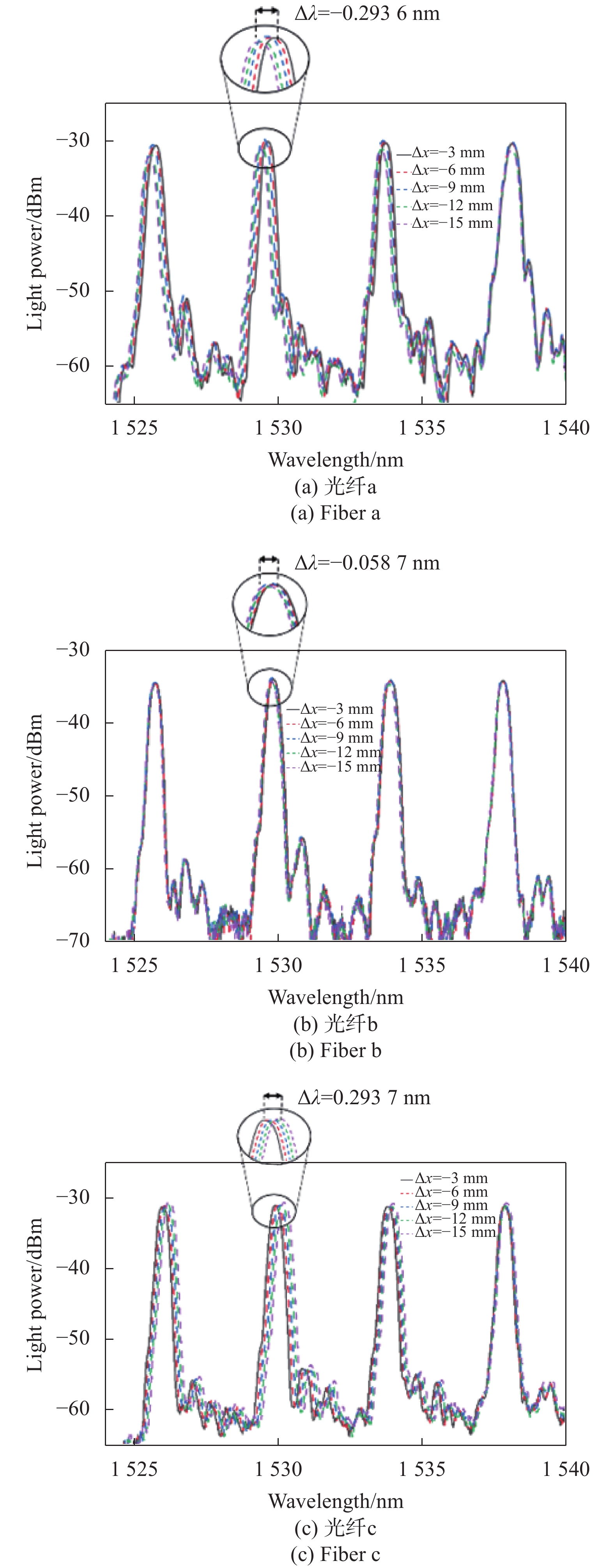
文中实验通过将介入手术探针尖端固定,利用运动控制系统控制探针在X轴上进行移动。当介入手术探针的末端位置偏移量变化范围是0~−15 mm时,实验测得光纤光栅的光谱变化如图10所示。用寻峰算法计算得到每个FBG中心波长的漂移量,实验分析得出,当介入手术探针的末端位置偏移量(
$ \mathrm{\Delta }x $ )由0变化到−15 mm时,光纤a和光纤b的每个FBG光谱的峰值逐渐向波长减小的方向移动,光纤c的峰值逐渐向波长增大的方向移动。利用FBG中心波长漂移量和插值算法可以建立介入探针变形测量的数据库,即不同的偏移量与FBG的不同中心波长漂移量呈现一一对应的关系。分析图10可以得出不同光纤的中心波长漂移量的绝对值随着介入手术探针末端偏移量的增加而增大,并且呈现线性关系。
Figure 10. Wavelength shift of three fibers in different positions
分析图10可得,位于探针中部的FBG所承受的剪切力最大,FBG中心波长漂移对末端位置的响应程度与传感位置有着密切关系。并且由于三根光纤呈120°分布,探针弯曲时不同位置的光纤受到的拉伸、压缩作用不同。我们设定拉伸状态是正应变,压缩状态是负应变,因此光纤a、光纤b上受到压缩作用,FBG中心波长漂移和末端位置的关系为单调递增,光纤c收到拉伸作用,FBG中心波长漂移和末端位置的关系为单调递减。
加入应变灵敏度矩阵前后的测量结果如图11所示。把使用应变灵敏度理论值的测量结果与加入实测应变灵敏度矩阵的测量结果进行比较,比较结果如表3所示。分析表格得出,随着末端偏移量的增加,形状测量的误差也在逐渐递增。文中使用绝对误差
${{r}}_{e}(k)$ 、相对误差${{r}}_{em}(k)$ α对视觉测量系统和光纤传感系统进行性能评估,计算公式如下所示:式中:
$ \Upsilon (k)$ 为形状测量系统测量结果;$ \gamma \left(k\right) $ 为末端偏移量理论值。在不同弯曲状态下,加入应变灵敏度矩阵的介入手术探针末端偏移量的平均误差为0.415 mm,最大误差为0.601 mm,最大误差百分比为4.01%。相对于没有进行传感器应变灵敏度标定的系统,利用文中提出的方法测量介入手术探针末端偏移量与算法改进前相比。平均误差降低了1.385 mm,最大误差降低了3.317 mm,说明该方法可有效提高测量精度。
Figure 11. Reconstruction results of needle under different deformation
Deformation theoretical value/mm −3 −6 −9 −12 −15 Shape reconstruction without sensitivity matrix/mm −2.181 −5.920 −10.684 −14.498 −18.918 Absolute error/mm 0.819 0.08 1.684 2.498 3.918 Relative error 5.46% 0.53% 11.23% 16.65% 26.12% Shape reconstruction with sensitivity matrix/mm −2.896 −5.667 −8.538 −11.425 −14.399 Absolute error/mm 0.104 0.333 0.462 0.575 0.601 Relative error 0.69% 2.22% 3.08% 3.83% 4.01% Table 3. Deformation measured error analysis of X-axis
-
(1)针对介入手术探针等微创柔性医疗器械形状测量的需求,提出一种引入应变灵敏度矩阵的光纤光栅传感阵列介入探针形状测量方法。为了验证引入应变灵敏度矩阵对形状测量精度的影响,文中对植入光纤光栅传感阵列的介入探针进行了不同弯曲状态下的形状测量实验。
(2)实验结果表明,引入光纤光栅应变灵敏度矩阵可有效提升介入探针的测量精度。在不同弯曲情况下,介入手术探针末端偏移量测量平均误差降低了1.385 mm,最大误差降低了3.317 mm,相对误差降低了22.11%。
(3)在后续研究中,将探针形状测量方法与高速解调处理系统相结合,实现高精度实时测量,在柔性医疗器械及手术机器人精准测控领域中具有广阔的应用前景。
Needle shape optical fiber measurement method introducing strain sensitivity matrix
doi: 10.3788/IRLA20210623
- Received Date: 2021-08-30
- Rev Recd Date: 2021-10-08
- Publish Date: 2021-12-31
-
Key words:
- fiber Bragg grating /
- strain sensitivity /
- shape sensing /
- interventional needle
Abstract: Interventional needle shape monitoring method can provide doctors with important information during surgery and is a necessary means to ensure the safety of surgery. In order to improve interventional needle shape measurement accuracy, a fiber grating sensor (FBG) array was presented, which introduced a strain sensitivity matrix to measure the shape of the probe. Firstly, based on the theory of FBG, the relationship between the wavelength shift of the fiber grating implanted in the probe and its strain was analyzed, and the strain sensitivity matrix was introduced, the relationship between the FBG center wavelength shift and its bending curvature was studied. Then the geometric parameter relations and coordinate transformation equations of the needle's local elements were deduced, and the needle shape reconstruction model based on fiber grating was established. Finally, in order to verify the influence of introducing the strain sensitivity matrix on the shape measurement accuracy, the shape measurement experiment of the intervention needle implanted with the FBGs array under different bending states was carried out, and the error of the shape measurement before and after the strain sensitivity matrix was compared and analyzed. The experimental results show that the introduction of the FBG’s strain sensitivity matrix can effectively improve the measurement accuracy of the needle. Under different bending conditions, the average error of the end of the interventional surgical needle is reduced by 1.385 mm, and the maximum error is reduced by 3.317 mm. The shape measurement method based on FBGs array proposed in this paper has broad application prospects in the direction of shape measurement of flexible medical instruments in interventional surgery.


 DownLoad: