


-
光纤布拉格光栅作为一种常见光纤无源器件,具有体积小、稳定性高、成本低廉、易与光纤连接、插入损耗低等优点。通过改变其折射率调制方式,可以灵活多样地实现对波长的选择,达到带通滤波的效果,因此目前被广泛应用于光纤激光技术、光纤传感和光纤通信等领域[1-3]。
线性啁啾光纤光栅(Linearly Chirped FBG,LCFBG)具有较宽的反射带宽和出色的色散补偿能力,常被用于波分复用系统、色散补偿和激光脉冲压缩等应用技术中[4-5]。而啁啾相移光纤光栅,则是将啁啾光纤光栅的宽带特性与相移光纤光栅的窄带透射窗口特性相结合,通过在栅区控制相移突变点的大小、位置和数量,便可在透射禁带中实现一个或多个带宽较窄、透射率可控的透射窗口,因此可用于窄线宽单频光纤激光器、光通信中的多路波分解复用等应用中[6-7]。利用传统的相位掩模板法制作啁啾相移光纤光栅,虽然制作过程较为简单,可重复大量制备,但是只能制作固定透射窗口的啁啾相移光纤光栅,且掩模板价格较为昂贵。其他诸如遮挡法、二次处理法、相位掩模板移动法,在相位突变引入精度控制方面要求较高,且重复性不甚理想[8-9]。此外,啁啾光纤光栅中相移的引入,还可通过对栅区局部进行外部调制的方法来实现,且这种外部调制引起的相移变化具有可逆性、响应速度快等特点。例如,利用压电陶瓷在栅区某一位置施加外力,通过改变驱动电压实现该位置栅区处的微小形变,从而获得可调谐相移突变[10]。这种引入相移的方法具有调节简单、可准确控制相移量等优点,但相移点位置固定,相移点数量受压电陶瓷数量所限制。相对于施加外力的方式,通过对栅区进行局部点加热而引入瞬时相移的方法,则成本相对低,在引入相移点的数量、位置等方面操作更为灵活方便[11]。
文中对线性啁啾光纤布拉格光栅进行局部点加热时,在不同情况下的输出光谱特性进行了深入而系统的研究。基于数值模拟的结果,利用可编程热敏打印头的加热阵列作为局部点加热源,通过控制加热温度、加热宽度以及加热位置,对LCFBG在局部点加热时的输出光谱特性进行了实验验证。
-
LCFBG是光栅周期Λ(z)沿光栅轴向呈线性变化的啁啾光纤布拉格光栅。由于不同栅区位置处的光栅周期对应不同的布拉格反射波长,根据布拉格反射波长公式:
可知,LCFBG可具有很宽的反射带宽。公式(1)中,neff为LCFBG纤芯的有效折射率,光栅周期Λ(z)
可表示为: 式中:Λ0为LCFBG栅区中心位置对应的初始光栅周期,啁啾系数
$C{\text{ = }}\dfrac{{{\rm{d}}{\lambda _D}}}{{{\rm{d}}z}}$ [12]。由光栅周期啁啾化引入的相移量为:从上式可以看出,LCFBG的相移变化与有效折射率、光栅周期等参数密切相关。而这些参数对诸如温度、应力等外界条件的变化较为敏感。当温度发生变化时,光栅周期和有效折射率都将发生如下变化[13]:
式中:ξ为热光系数;α为热膨胀系数;ΔT为温度变化量。同时,布拉格波长也将发生漂移:
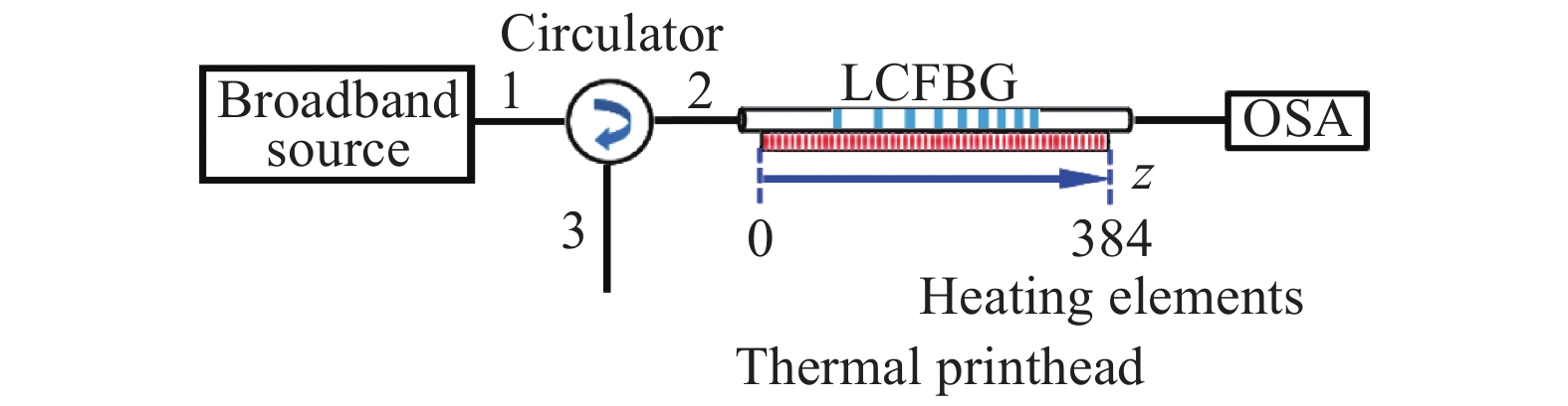
根据公式(3)可知,如果对LCFBG栅区某一局部位置进行加热(如图1所示),其栅区的线性啁啾特性将会被破坏,在该位置处的相移量将会发生突变。这将和啁啾相移光纤光栅一样,在其透射禁带中会产生一窄带透射峰。通过改变LCFBG局部加热点的位置z、温度
ΔT、宽度ΔL和数量等参数,其透射禁带中透射峰的透射率、中心波长、带宽以及透射峰个数亦将随之发生变化。 
Figure 1. Schematic of the local heating model of LCFBG
-
根据上述理论分析,采用光纤光栅传输矩阵法,对局部点加热的LCFBG输出光谱特性进行了理论模拟。设定宽带高反LCFBG栅区中心位置对应的布拉格波长λ0=1550 nm,栅区长度L=15 mm,有效折射率neff=1.453,啁啾系数C=2 nm/cm,此时透射禁带宽度约为2.45 nm(不是透射谱带宽)。需要说明的是,在数值模拟过程中,没有考虑在LCFBG栅区局部加热位置两侧存在的热传导现象。
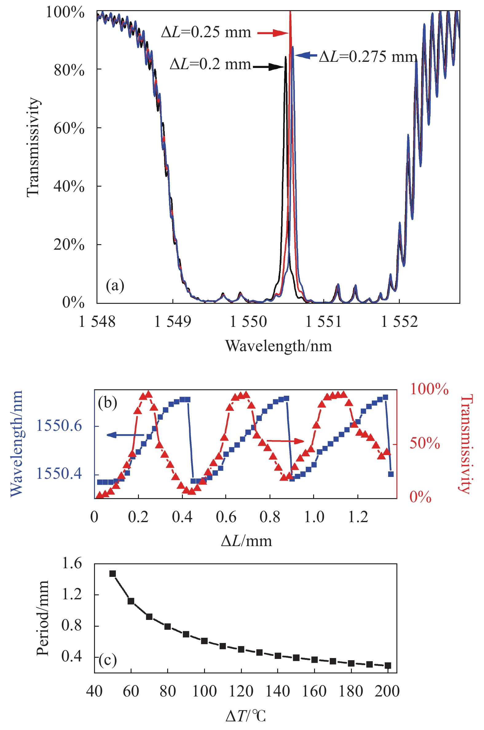
当对LCFBG栅区中心位置处进行局部点加热,且加热宽度ΔL=0.25 mm时,在温度变化
ΔT分别为110 ℃、135 ℃和150 ℃的情况下,其透射光谱图如图2(a)所示。从图中可以看出,当ΔT在135 ℃附近时,温度变化引起的相移突变量Δφ接近π,窄带透射峰的透射率接近100%,且其中心波长位于LCFBG透射禁带的中心位置附近。随着温度变化量 ΔT增大,该窄带透射峰的中心波长将向长波长方向移动,且由于相移突变量Δφ具有周期性,透射峰中心波长将在小于透射禁带宽度的一定范围(Δλ=0.34 nm)内,随ΔT以周期约为225 ℃的规律变化。同时,窄带透射峰的透射率以相同的温度变化周期发生规律性变化,如图2(b)所示。该周期的大小主要受加热宽度ΔL的影响,如图2(c)所示。随着加热宽度的增加,该周期值逐渐减小,且减小趋势逐渐平缓,而窄带透射峰在透射禁带范围内的扫描范围 Δλ基本上不随加热宽度的增加而发生变化。 
Figure 2. (a) Transmission spectrum of LCFBG under the different temperature changes ΔT and ΔL=0.25 mm; (b) Central wavelength and transmittance of narrow-band transmission peaks versus ΔT under ΔL=0.25 mm; (c) Period and scanning range of the central wavelength (or transmittance) of narrow-band transmission peaks versus ΔL
图3(a)为加热位置仍在LCFBG栅区中心位置处,温度变化ΔT=135 ℃时,不同加热宽度ΔL对应的透射谱。透射峰的中心波长随着加热宽度的增加而在LCFBG透射禁带中较小范围内发生红移。当加热宽度ΔL=0.25 mm时,透射峰的透射率接近100%,且其对应的中心波长处于透射禁带的中心位置附近。在此条件下,加热宽度每改变大约0.45 mm,透射峰中心波长和透射率均完成一次周期性变化,如图3(b)所示。该周期的大小随着加热温度变化量
ΔT的增加而逐渐减小,如图3(c)所示。 
Figure 3. (a) Transmission spectrum of LCFBG under the different heating width ΔL and ΔT=135 ℃; (b) Central wavelength and transmittance of narrow-band transmission peaks versus ΔL; (c) Period of the central wavelength (or transmittance) of narrow-band transmission peaks versus
ΔT 由上述数值模拟结果可知,无论是改变温度变化量ΔT,还是改变加热宽度ΔL,主要都是影响LCFBG栅区被加热部分的相移突变量Δφ。而由Δφ的变化引起的透射峰波长的漂移,其变化范围明显小于透射禁带的宽度。
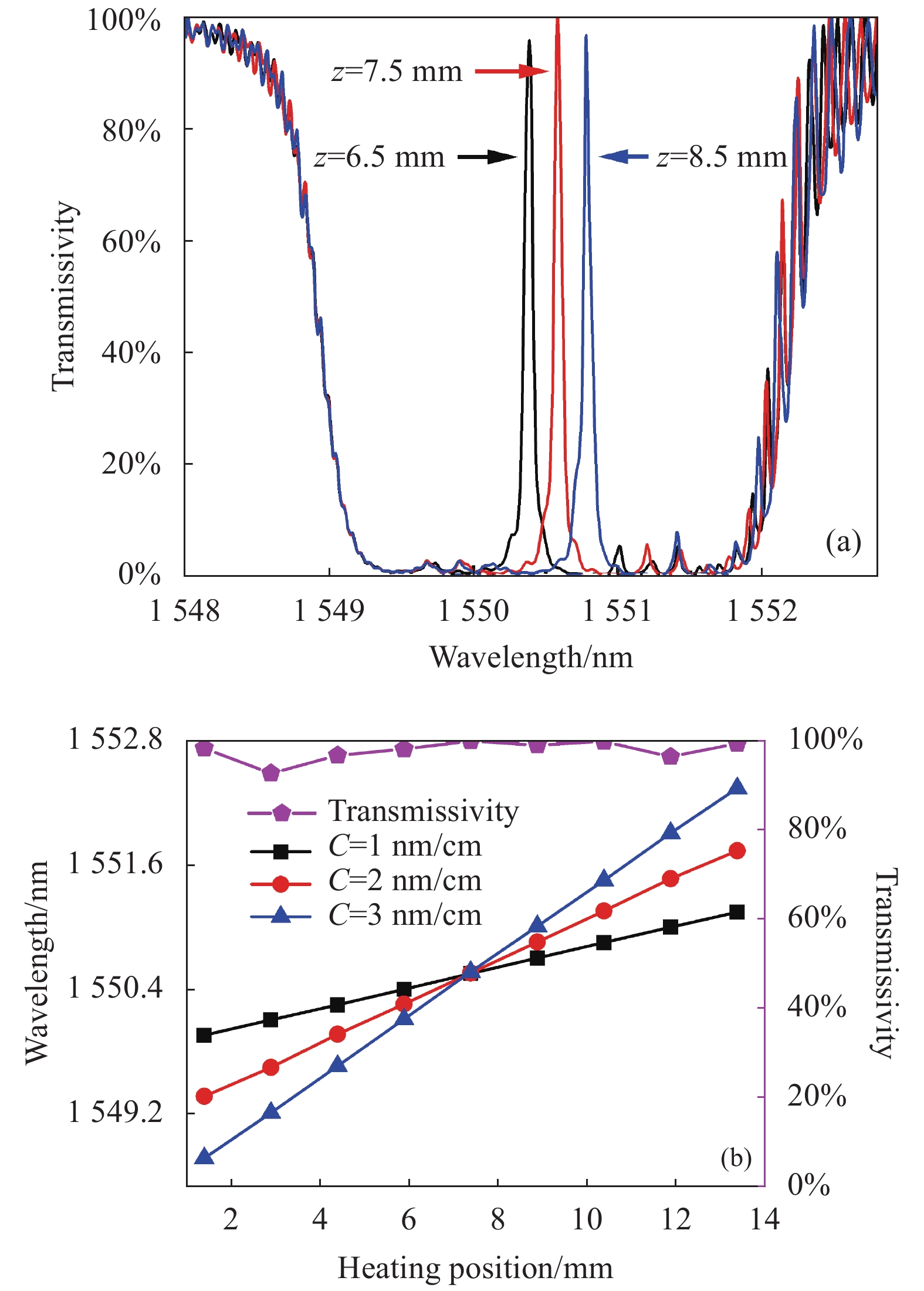
当加热宽度
ΔL=0.25 mm,温度变化ΔT=135 ℃时,对距LCFBG栅区一端z=6.5 mm、7.5 mm和8.5 mm处分别进行加热,其透射光谱如图4(a)所示。当加热位置位于LCFBG栅区中心时,其窄带透射峰中心波长亦位于透射禁带的中间位置,而当局部加热点分别位于栅区中心两侧对称位置时,其产生的透射峰亦相对于透射禁带中心呈对称分布。若在LCFBG整个栅区范围改变加热位置,则可在整个透射禁带范围内实现窄带透射峰,其中心波长与加热位置呈现线性变化规律,如图4(b)所示。除在LCFBG栅区边缘位置外,加热位置的变化对窄带透射峰的透射率影响较小。LCFBG啁啾系数C的大小决定了透射峰波长随加热位置的变化速率。从图4(b)可知,对啁啾系数较大的LCFBG栅区进行局部点加热,可实现窄带透射峰波长的快速调谐。而若想实现窄带透射峰波长的精细调谐,则LCFBG的啁啾系数要较小。 
Figure 4. (a) Transmission spectrum of LCFBG under the local heating points located at 6.5 mm,7.5 mm and 8.5 mm from one end of the LCFBG, respectively; (b) Central wavelength and transmittance of transmission peaks versus heating position
-
图5为对LCFBG栅区进行局部点加热实验的实验装置图。实验中使用的宽带光源(HY-ASE-C-13-G-B-FA)输出带宽范围为1 527~1 565 nm。该宽带光源与中心波长为1 550 nm环形器(Circulator)的port1端相连接,port2端接于待测LCFBG的长周期端。在LCFBG后连接光谱分析仪(OSA, AQ6370C),用于对其透射光谱进行采集和分析。利用蓝丁胶将LCFBG紧贴固定于一商用行点式热敏打印头(PT486F)的加热阵列上。该加热阵列作为局部点加热源,其长度为48 mm,由384个尺寸为0.125 mm×0.12 mm的点加热单元(heating elements)线性排列组成,相邻点加热单元间距为0.125 mm。利用自编的控制软件和自制的控制电路,可灵活控制该加热阵列上的加热宽度(精度为0.125 mm)和工作时间,并可对加热阵列上四个不同区域同时进行加热。通过控制加热电脉冲信号的占空比大小,即可改变加热单元的工作温度。

Figure 5. Experimental setup of the local heating of LCFBG
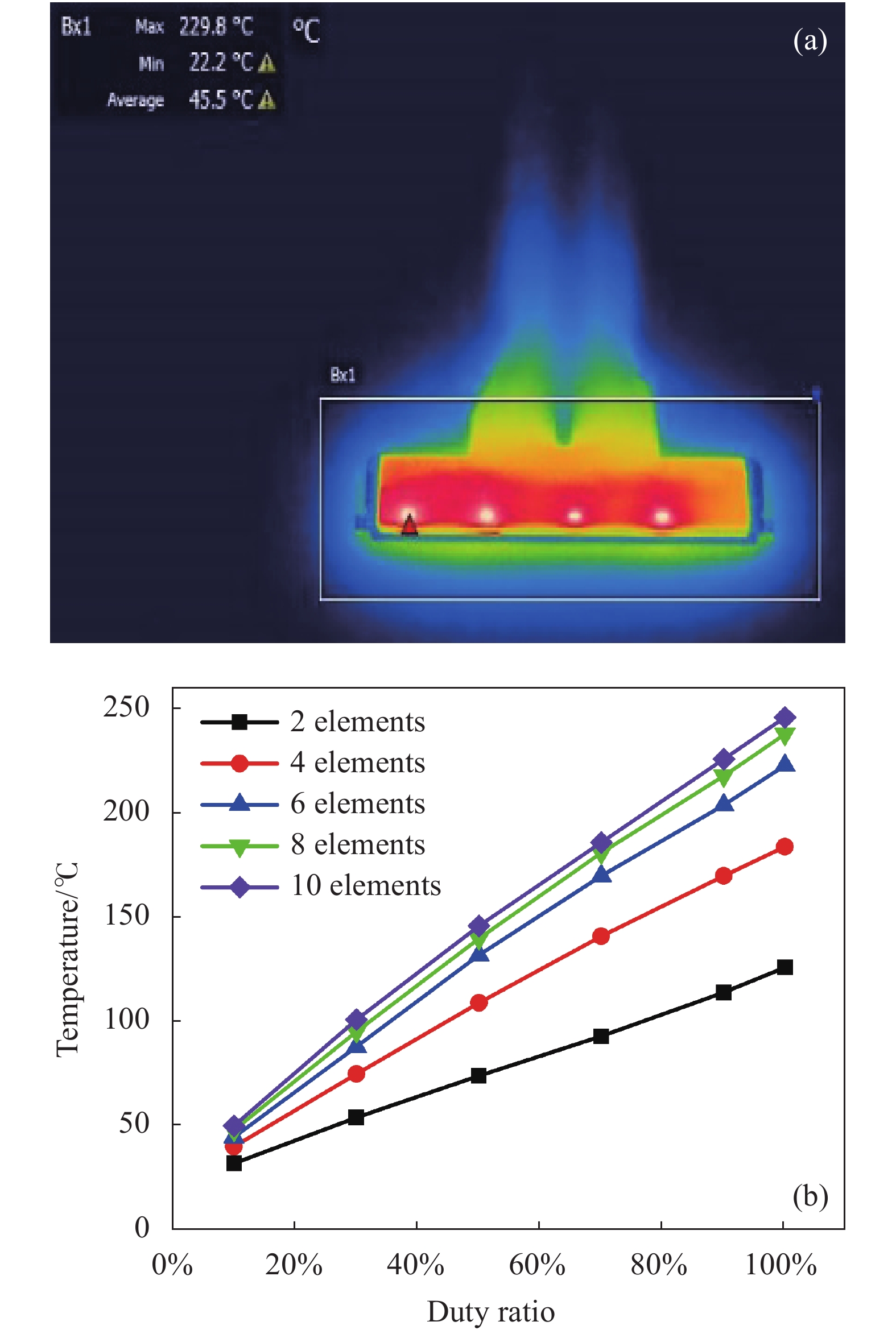
利用红外热像仪(FLIR-T620)对该热敏打印头加热阵列在工作时的温度进行了测量,如图6所示。图6(a)为四个加热区域(加热宽度为1.25 mm,即10个连续点加热单元)同时工作,在加热占空比为90%时的红外热像图。由于控制电路中控制四个加热区域的电路电阻大小有微小差异,导致不同加热区域同时工作时的温度略有不同。另外,相邻加热区域之间存在一定的热传导现象。图6(b)为一个加热区域在不同加热宽度情况下的工作温度与加热占空比之间的关系图。从图中可以看出,热敏打印头加热区域的工作温度随加热占空比的增加而呈线性增加。在相同加热占空比情况下,加热宽度越宽,工作温度就越高。当加热宽度超过8个加热点(即加热宽度为1 mm)后,工作温度逐渐趋于定值。当加热占空比为100%时,工作温度接近250 ℃。

Figure 6. (a) Infrared thermal imaging of four heating regions on the thermal printhead with a duty ratio of 90%; (b) Temperature curves of one heating region with different consecutive heating elements on the heating array versus heating duty ratio
-
实验所使用的LCFBG栅区长度为15 mm,透射禁带宽度约为9 nm,中心波长约为1 552 nm。需要指出的是,由于在实验中无法保证LCFBG的整个栅区都能与热敏打印头加热阵列保持良好的均匀热接触,因此加热阵列的工作温度与施加在LCFBG栅区上的实际温度有一定的差别,从而可能导致实验结果与前述数值模拟结果存在一定的误差(例如在透射峰幅值等方面)。另外,在实际实验中,LCFBG栅区加热区域两侧存在一定热传导现象,因此得到的实验现象与数值模拟的结果亦会存在一定的偏差。然而,这些因素不会影响其最后的规律性实验结果和结论。在实验中为了保证测量的准确性,所有的实验数据都是在加热单元工作15 s之后,LCFBG栅区上的温度达到稳定时才开始测量。
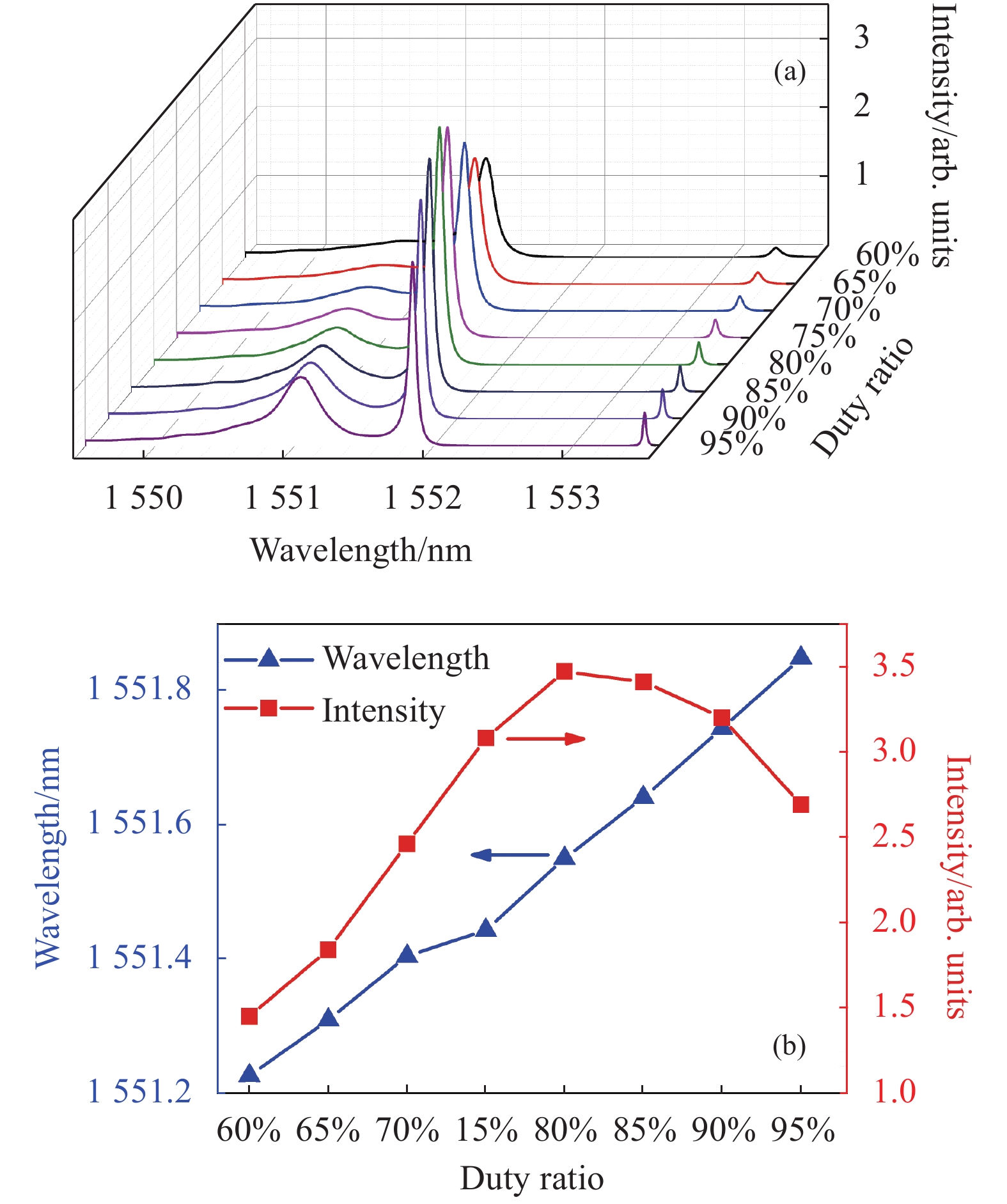
图7(a)为加热宽度为0.625 mm (即有连续5个点加热单元同时工作),对LCFBG栅区中间位置附近进行局部点加热,在不同加热占空比情况下的LCFBG透射光谱。从图中可以看出,在其透射禁带中产生了明显的窄带透射峰。随着加热占空比的增加,透射峰中心波长向长波长方向发生漂移,而透射峰的幅值先增大后减小,在加热占空比为80%时达到最大值,如图7(b)所示。这说明此时栅区的相移突变量Δφ更接近π。另外,当加热占空比较大时,LCFBG栅区加热位置的两侧存在明显的热传导现象。这种加热区两侧明显的温度梯度变化,将会破坏其附近栅区的线性啁啾特性,导致在窄带透射峰两侧出现了较为明显的寄生透射峰,尤其是短波长一侧。随着寄生透射峰的逐渐变强,主透射峰的线宽和透射幅值都会受到影响。

Figure 7. (a) Transmission spectra for different heating duty ratios; (b) Central wavelength and intensity of transmission peaks versus heating duty ratio
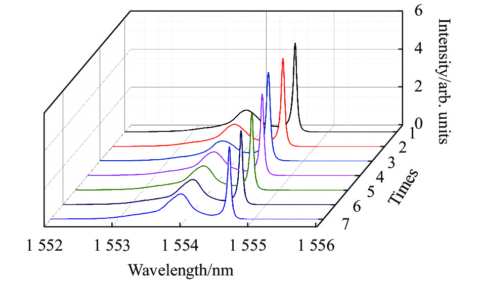
为了测试这种LCFBG栅区局部点加热产生的窄带透射峰的输出稳定性,对其在加热宽度为0.75 mm (6个加热点)、加热占空比为80%情况下产生的窄带透射峰进行了多次重复测量,如图8所示。从图中可以看出,窄带透射峰的中心波长和透射幅值基本不变,其各自的波动率分别为0.01%和7.6%。表明这种基于热敏打印头,对LCFBG栅区进行局部点加热获得的窄带透射峰具有良好的光谱稳定性和重复性。

Figure 8. Stability of transmission spectra
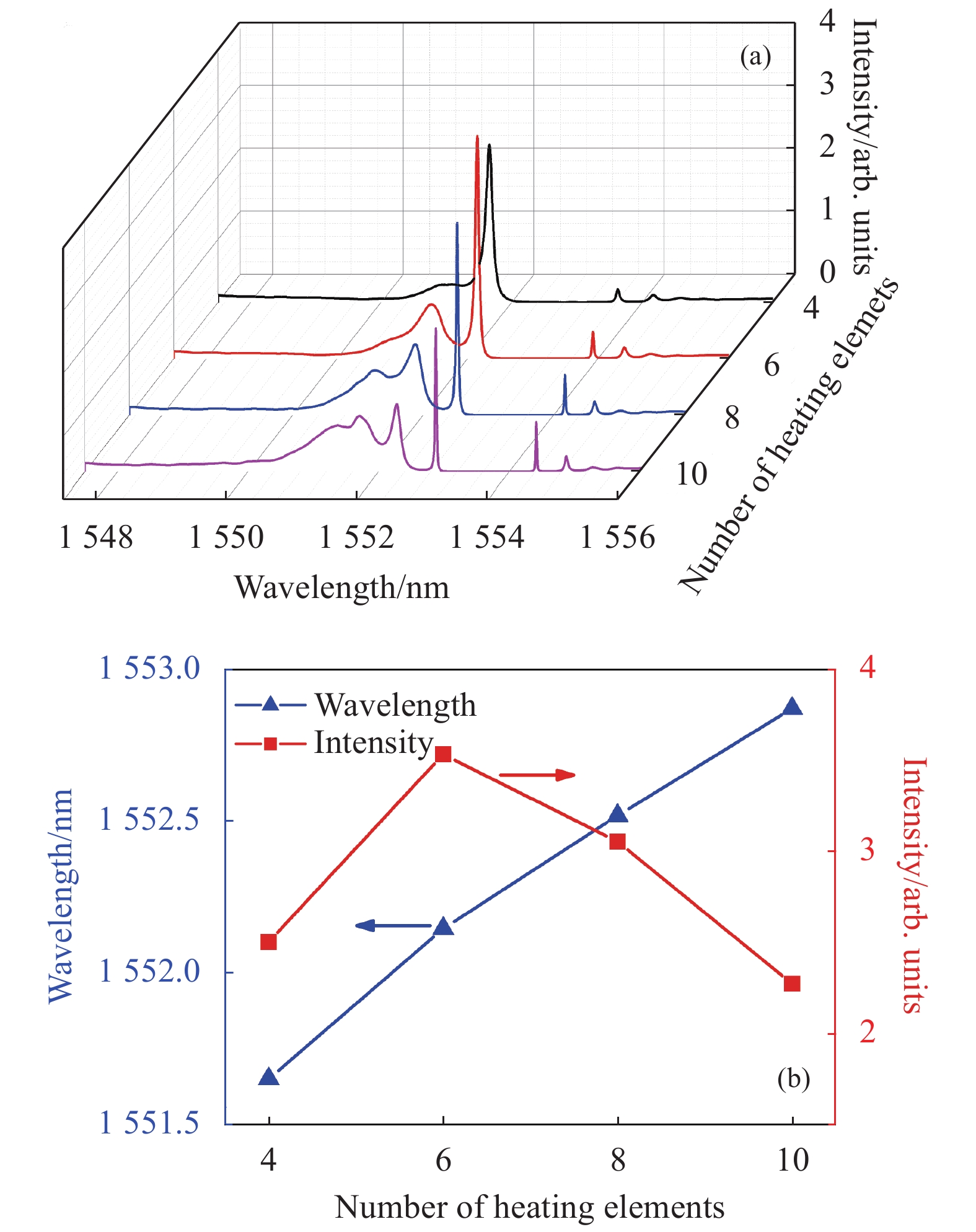
图9(a)为保持85%的加热占空比不变,在加热宽度分别为ΔL=0.5 mm、0.75 mm、1 mm和1.25 mm(即对应点加热单元的数量分别为4、6、8和10)时LCFBG的透射光谱图。随着加热宽度的增加,窄带透射峰的中心波长发生了明显的红移现象,并伴随出现了明显的寄生透射峰。在ΔL=0.75 mm时,透射峰的幅值达到最大值,如图9(b)所示。这表明在该加热宽度情况下,温度变化导致栅区在该位置处的相位变化量最接近π。从理论上讲,增大栅区加热宽度,产生的透射峰线宽应该也随之变宽。然而在实验中发现,当增大加热宽度时,主透射峰的线宽反而逐渐变窄,而短波长侧的寄生透射峰愈加明显。究其原因可能是随着加热宽度的增加,被加热栅区部分两侧的热传导现象愈发显著,产生的寄生透射峰逐渐增强(甚至出现了高阶寄生透射峰),导致主透射峰的透射幅值和线宽都有所降低。

Figure 9. (a) Transmission spectra for different heating widths; (b) Central wavelength and intensity of the transmission peaks versus the heating width
对LCFBG 栅区不同位置进行局部点加热时,其透射光谱如图10(a)所示。实验中,加热宽度和加热占空比分别为0.75 mm和80%。图中z轴表示在图5中的热敏打印头加热阵列从最左端开始计数时的点加热单元的序数,以此表示加热区域的中心位置。从图中可以看出,改变栅区加热位置,可以在LCFBG透射禁带内实现较大范围的透射峰波长调谐,且窄带透射峰中心波长与加热位置具有明显的线性对应关系。由此可知,当对LCFBG栅区的多个位置同时进行局部点加热时,便会在透射禁带中同时产生与加热位置相对应的透射峰,如图10(b)所示。这就意味着,如果连续改变栅区加热位置,就可在LCFBG透射禁带范围内获得多波长、连续可调谐窄带透射峰。实验中,与不同加热位置对应的各个透射峰的幅值存在一定差别,其原因主要是由于LCFBG栅区加热部分与热敏打印头加热阵列之间热接触不良所致。

Figure 10. Transmission spectra for different heating positions (Inset: central wavelength of narrow-band transmission peaks versus heating position); (b) Transmission spectra under multi-position heating
-
文中对LCFBG栅区进行局部点加热时的输出光谱特性进行了理论与实验研究。通过数值模拟发现,改变栅区局部点加热位置的温度和宽度,对透射禁带中窄带透射峰的透射率有较为明显的规律性影响;窄带透射峰的中心波长与栅区的局部点加热位置存在线性对应关系,且透射峰波长变化范围理论上可覆盖整个透射禁带;LCFBG啁啾系数的大小,则会影响其波长调谐速率。为了验证理论研究结果,利用商用热敏打印头的加热阵列对LCFBG栅区进行了局部点加热的实验研究。基于此实验装置,当对LCFBG栅区进行局部点加热时,在透射禁带中产生了与加热位置一一对应,且重复性和稳定性都较好窄带透射峰;改变局部加热点的温度或宽度,会使得窄带透射峰的中心波长在透射禁带一定范围内发生漂移。在实验误差范围内,实验结果与数值模拟得到的结论较为一致。这种通过对LCFBG栅区进行局部点加热而灵活实现窄带透射峰的方法,使其在窄线宽激光器的滤波、选模、波长调谐,以及光纤通信中的多路波分解复用等方面,都将具有较大的实用价值和应用潜力。
Investigation of the spectral characteristics of a linearly chirped fiber Bragg grating with local point heating
doi: 10.3788/IRLA20210708
- Received Date: 2021-09-26
- Rev Recd Date: 2021-10-09
- Publish Date: 2022-08-31
Fund Project:
Natural Science Foundation of Shaanxi Province(2022JM-406);National Key Research Instrument Development Project(51927804)
-
Key words:
- linearly chirped fiber Bragg grating /
- local point heating /
- phase change /
- narrow-band transmission peaks
Abstract: The output spectrum characteristics of a linearly chirped fiber Bragg grating (LCFBG) under localized point heating with different heating temperatures, widths and positions were investigated. The numerical simulation shows that the heating temperature and heating width applied onto the LCFBG have an obvious influence on the transmissivity and central wavelength of narrow-band transmission peaks in the transmission bandgap. The central wavelengths of the transmission peaks have a good linear relationship with the local heating positions of the LCFBG and can shift in the whole transmission bandgap region. The chirp coefficient of the LCFBG determines the wavelength tuning velocity of the transmission peaks induced by the change in the heating position. Based on the theoretical results, the spectral characteristics of the LCFBG are investigated experimentally using a commercial thermal printhead as a local heating source. The narrow-band transmission peaks are realized with high performance in terms of reproducibility, stability and potential multiwavelength tunability. The experimental results are in good agreement with those of the numerical simulation within the experimental error.


 DownLoad: