


-
低温辐射计在对光谱辐射的计量过程中提供了最低的不确定度,因此被用作最高计量基准,并被广泛应用于辐射测量学、光辐射计量学、光谱学和天体物理学等领域。低温辐射计采用电替代原理,其核心部件-黑体吸收腔对相同的电功率或光功率输入表现出相同的温升。由于工作在液氦温度下,低温辐射计突破了环境和材料的限制,不确定度比常温电替代辐射计降低约一个量级,达到10−4[1-4]。目前在光辐射计量领域,低温辐射计已经成为国际标准化研究机构公认的探测器一级基准,也是光辐射绝对功率测量的一级基准。
低温辐射计的电替代原理需要光功率和电功率相等时吸收腔产生相同的温升,但由于吸收腔结构参数、涂层吸收率等因素的影响,黑体吸收腔出口的逸出辐射导致光电不等效性。因此,需要对低温辐射计吸收腔进行光电不等效性分析。美国NIST T. R. Gentile等人进行了不同激光功率Pm照射条件光电不等效系数ηm研究,吸收腔的光电不等效性在不同入射功率下引入的测量不确定度约为0.002%[5]。此外,在光电加热过程中,吸收腔存在温度梯度,光加热位置和电加热丝布置位置的不同,导致光电不等效性的产生。为减小光电不等效性对辐射测量结果的影响,国内外技术人员开展大量的相关研究,方伟等采用将加热丝埋在锥腔内的方法[6-7],唐潇等运用有限元单元法对绝对辐射计的光电不等效性进行修正[8-11],成功将绝对辐射计的测量不确定度降低至5×10⁻⁶以下。杨振岭等对星载太阳辐照度绝对辐射计测量结果的真空-空气腔温响应变化进行了对比[12-13],得到空气中的相对修正系数。上述研究讨论了低温辐射计系统的不确定性来源,并将其归类分为光功率照射条件的差异和光电加热区域的差异导致的两类不等效性。但是,当前对这两类不等效性的来源仍缺少清晰的认知,其主要原因可归结于黑体腔对光照射的非平坦吸收特性及光-电加热路径的不重合特性。为解决上述两点关键问题,需要结合黑体涂层的变波长吸收特性,对吸收腔光加热路径进行分析:激光入射到腔体后,大部分光子经涂层的吸收,能量经声子弛豫过程转换为热能。因此,腔体对激光能量的吸收及热转换可以通过辐照度来体现。基于蒙特卡洛光线追迹法,文中对内壁涂敷碳纳米管的吸收腔中光功率的空间分布进行了仿真,并分析了吸收腔斜底板和下侧面对入射光功率的吸收比,以及光斑的形状、尺寸、位置。根据仿真结果,为使光加热路径和电加热路径尽可能完全相同,需在吸收腔斜底板和下侧面同时布置加热器,两个加热器的加热功率比例为51.2∶1,以改善低温辐射计光电不等效性,为低温辐射计的研制提供设计依据。
-
低温辐射计的吸收腔在测试过程中作为光陷阱,入射到腔中的辐射经过多次反射后被近似完全吸收,并经光热转换导致腔体温度的变化。通常吸收腔内壁涂黑材料吸收率越高、吸收腔内表面积与开口面积的比值越大,越有利于获得高吸收率。目前,国内外的低温辐射计多采用带斜底的圆柱腔,斜底角多为30°和60°。在吸收腔内壁涂黑材料性质相同的情况下,斜底角为30°相对于60°时具有略高的吸收率[5]。文中采用垂直排列碳纳米管作为发黑涂层,由于垂直排列阵列中的碳纳米管包含多种手性、多种壁厚,因此带隙分布展宽极大(0.1~4.0 eV),对全波段均能表现出吸收特性。此外,该类碳纳米管具有森林结构,引入了多重反射-吸收模式,极大提升了其光子束缚能力。其变波长镜面反射率如图1所示,当入射辐射波长延伸到6 μm以上,材料吸收率随入射角增大而急剧降低,当波长延伸至16 μm,纳米涂层的反射率可高达1.25%。该现象主要归因于长波光子较低的能量及较长的波长,难以通过激发吸收涂层本征电子禁带跃迁的方式实现光-电弛豫,只能在纳米森林结构中通过多次反射、缺陷激发等方式逐步降低能量。而随入射角的降低,纳米管阵列对光子的束缚能力大为提升,当入射角降低至30°,全波段反射率低至0.25%以下,满足低温辐射计设计需求,因此文中所讨论的低温黑体腔斜底角设计为60°。
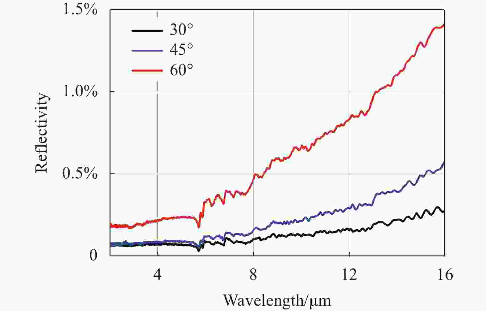
Figure 1. Specular reflectance measurement curve of carbon nanotubes absorbing black materials at different incident angles
在斜底面倾角以及内壁涂黑材料确定时,增加腔长能有效地将光线限制在腔内,增加腔内反射次数,随着黑体腔长的增加,平均垂直有效吸收率单调上升。取腔体平均直径
$ \phi $ =10 mm、$ \theta $ =60°,在LightTools软件中,结合蒙特卡洛逆向光线追迹算法对不同腔长,不同内壁涂黑的黑体腔平均垂直有效吸收率进行计算,所得腔体有效吸收率如表1所示,ρ为内壁涂黑层的吸收率,L为腔体长度。对相同的内壁涂层吸收率,增加黑体腔内表面积与开口面积的比值,有利于获得高吸收率。但随腔长的延伸,腔体热容增加,将导致吸收腔响应时间的增加。基于积分球法测得碳纳米管吸收黑材料的光谱吸收率达到0.98,黑体腔腔长L选取为40 mm即可获得低于0.001%的吸收腔反射率。ρ=0.85 ρ=0.90 ρ=0.95 L=30 mm 0.99826 0.99964 0.99994 L=40 mm 0.99977 0.99991 0.99999 L=50 mm 0.99998 0.99999 0.99999 Table 1. Calculation results of average vertical effective absorption rate of cylindrical cavity with inclined bottom
为了仿真低温辐射计吸收腔内的功率分布,最终确定吸收腔模型结构参数为:长度40 mm、内径10 mm、壁厚0.1 mm、斜底角60°。
-
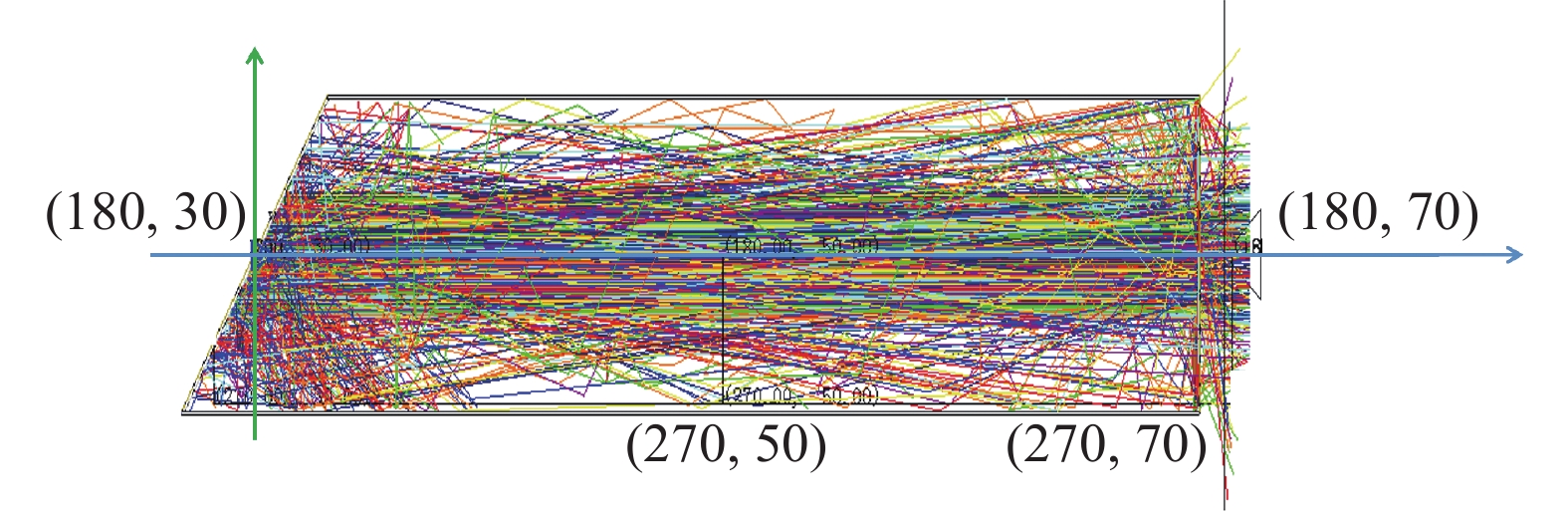
为精确反映激光在吸收腔内部的反射/吸收过程,在确定吸收腔结构参数的基础上,采用蒙特卡洛逆向光线追迹算法对吸收腔内辐照度分布情况进行仿真。光源设置为Φ4 mm的准直光束,波长为632.8 nm,功率为1 mW。为提高光线追迹的准确性,设置光线功率阈值为10−8,追迹光线数为2000000根,经积分球法测得吸收腔内壁涂层总吸收率为98%,减去镜面反射率(典型值为0.4%)得到漫反射率(1.6%),最终比值约为1∶4,考虑到激光的高斯分布属性,将镜面反射设置为高斯型反射。同时,设置光线路径追迹,以准确判断光线传播路径,吸收腔光线追迹的剖面示意图如图2所示。

Figure 2. Schematic diagram of ray tracing in absorption cavity
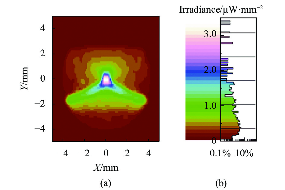
吸收腔出口处辐照度分布仿真结果如图3所示。图3(a)为出口截面的空间光场分布,出口辐照主要集中在腔体的下侧出口面。图3(b)进一步给出了溢出辐射的比例分布,80%以上比例的溢出能量低于2.5×10⁻⁶ W/mm2,总截面积分辐照度低于1×10−4 W,最终实现优于0.9999的腔体吸收率。
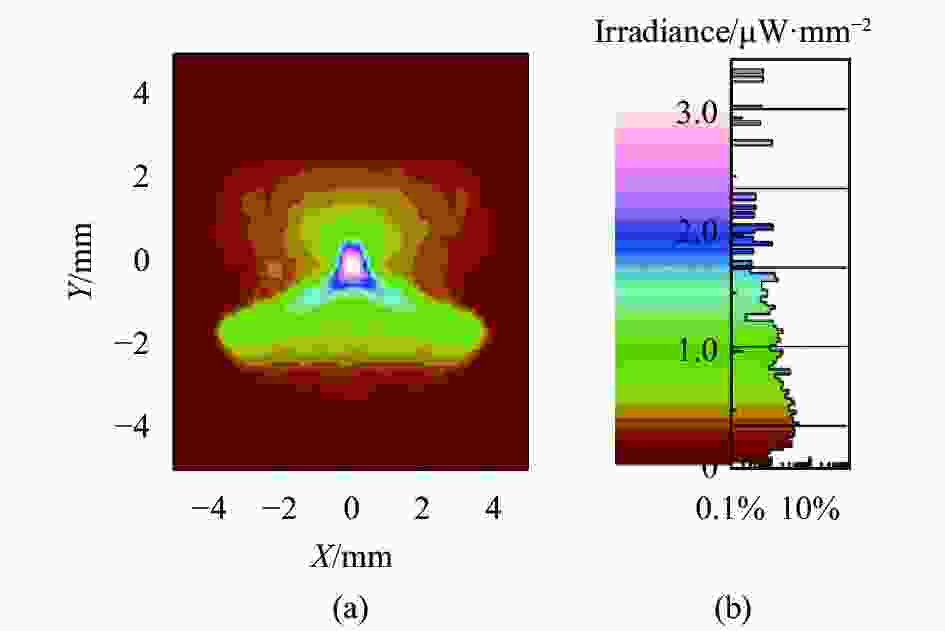
Figure 3. Simulation diagram of irradiance distribution at the outlet of absorption cavity
-
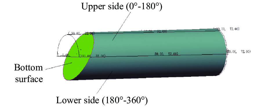
通过上述光线追迹仿真,得出吸收腔底面、上侧面(0°~180°)以及下侧面(180°~360°)的内表面辐照度分布情况和吸收能量大小,进一步为低温辐射计光电加热不等效的修正提供了参数支持,吸收腔区域划分如图4所示,腔体内侧面展开如图5所示。
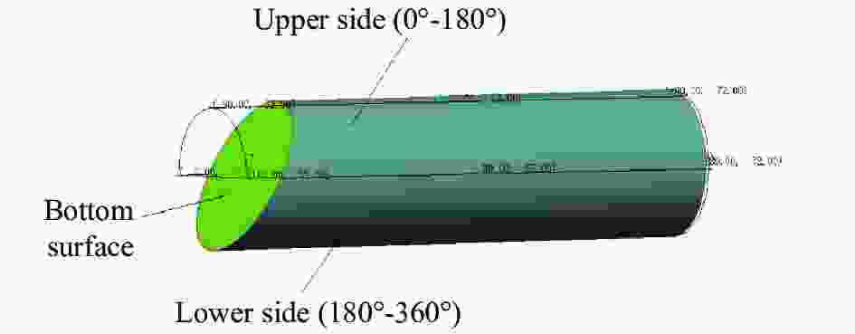
Figure 4. Schematic diagram of absorption cavity area division

Figure 5. Schematic diagram of lateral expansion of absorption cavity
图6~图8分别为吸收腔底面、上侧面、下侧面的辐照度分布仿真结果。如图6所示,斜底面吸收功率的位置集中在底面中心处,吸收光功率值为0.9800335587 mW,反射辐照度低于5×10⁻⁶ W/mm2。如图7、图8所示,整个腔体侧面吸收光功率的位置集中在腔体前端(靠近斜角),辐照度分布不均匀,上侧面和下侧面存在较大差异。下侧面吸收光功率为0.01915025923 mW,辐照度分布集中在腔体轴向0-20 mm位置处,主要集中在靠近倾斜角约4 mm处(图7(a)白色区域)。上侧面吸收光功率为0.000 729 7450 839 mW,辐照度分布集中在腔体轴向5~15 mm位置处。斜底面吸收功率是下侧面吸收功率的51.2倍,是上侧面吸收功率的1343倍。这种巨大的吸收功率差异源于腔体内壁吸收涂层的超高吸收率,光子在第一次与第二次反射中被集中捕获,而入射到上侧面的光子多来自于第三次甚至更高次反射的光子,因此吸收功率可以忽略不计。此外,如图7(b)、8(b)所示,实际在吸收腔上侧面、下侧面分别观察到0.8~3 μW/mm2及1.9~3 μW/mm2辐照度的区间缺失,该现象主要由系统中光子多次反射能量的阶跃衰减引起:辐照度定义为光照体在单位时间内,单位面积接受所有方向入射的光子数NP的取值,由于光子数量在每次反射过程中都会被涂层俘获一部分,导致光子数NP的不连续,进而出现断层特性。

Figure 6. Irradiance distribution of bottom surface of absorption cavity

Figure 8. Irradiance distribution of the upper side of the absorption cavity (0°-180°)

Figure 7. Irradiance distribution of the lower side of the absorption cavity (180°-360°)
-
上述精确的定位分析表明,斜底板吸收入射光功率集中均匀分布在斜底面中心长轴为4.62 mm、短轴为4 mm的椭圆形区域内,整个腔体侧面吸收入射光功率主要集中在腔体轴向0~20 mm位置处,主要集中在靠近倾斜角约4 mm处。据此,在上述两个椭圆区域内均匀缠绕加热丝并用低温胶固定。根据计算得到腔体底面与下侧面吸收光功率的比值,两段加热丝的加热功率比为51.2∶1,从而确保光加热路径和电加热路径尽可能完全相同,并且光加热和电加热的加热面积几乎一致,以有效改善低温辐射计光电不等效性。加热丝的外接引线为铌铋超导线,靠近加热丝的引线涂敷IMI-7031清漆并用低温胶固定在吸收腔斜底面和下侧面上,以确保电加热功率全部耗散在吸收腔内。最终吸收腔底座结构如图9(a)所示,吸收腔体如图9(b)所示。
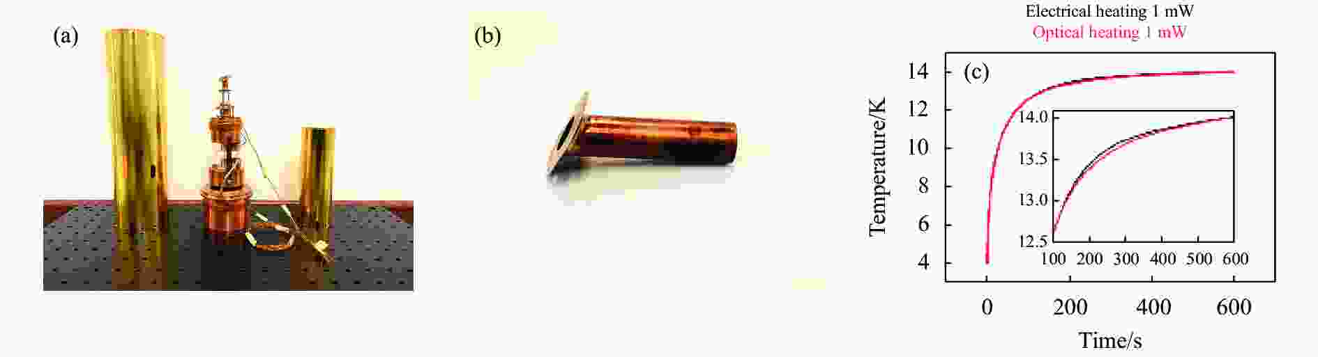
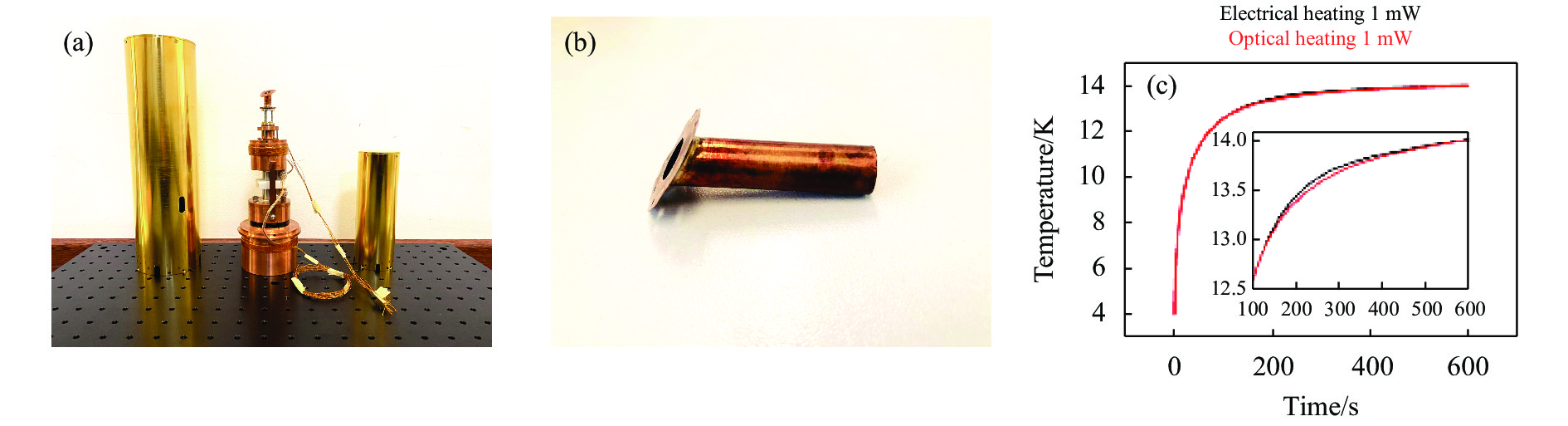
Figure 9. (a)Thermal link of cryogenic radiometer; (b) High absorption inclined bottom cavity of cryogenic radiometer; (c) Change of temperature of absorption cavity with time under different heating modes
为进一步研究腔体中的电-光不等效性,文中基于计算结果对腔体温度进行了仿真实验。对照组采用1 mW的电功率对腔体底面进行直接加热,实验组采用计算得到的光等效电功率对腔体进行加热,折合底面与吸收腔侧壁的功率分别约为0.98 mW与0.019 15 mW。在此基础上加热10 min,腔体温度随时间的演进如图9(c)所示:随着加热时间达到150 s以上,光加热与电加热产生的温升出现较大偏差(图9(c)插图),在温度的饱和区,两种加热方式的温度稳定的维持约为0.0007 K的温差(0.7 mK),这类温差主要由系统的热传导过程决定:吸收腔为达到热稳定,需经过热连接与热沉进行热交换,但是加热效率的差异将在系统中引入热交换效率的不等效性,并最终决定系统稳定温度。温差折合不等效性约为0.005%,与吸收腔温度梯度引起的不等效性相当,因此在实际设计过程中,需要采用多加热器的策略,尽量减小光电不等效性。
-
通过蒙特卡洛光线追迹方法,文中实现了对低温辐射计黑体腔的光场分布可视化处理。计算结果表明,黑体腔光电不等效性主要源于其出口溢出辐射,通过引入全波段吸收率高达95%的垂直排列碳纳米管,并进一步通过构建斜底角,将其反射率降低至0.25%以下,可有效提升黑体腔的吸收系数,并缩减黑体腔长度,降低系统热容,进而提升响应速度。文中指出,应当在黑体腔斜底面与下侧面布置加热丝,功率比设置为51.2∶1,以避免黑体腔温度梯度导致的光热不等效性,以提升测量准确度。
Design of the absorption cavity in the cryogenic radiometer based on the ray-tracing method
doi: 10.3788/IRLA20210918
- Received Date: 2021-11-29
- Rev Recd Date: 2021-12-14
- Accepted Date: 2021-12-28
- Publish Date: 2022-08-31
Fund Project:
Technology Foundation Project of State Administration of Science, Technology and Industry for National Defense(JSJL2018208A001)
-
Key words:
- cryogenic radiometer /
- optical-electrical non-equivalency /
- heater arrangement /
- ray-tracing method /
- absorption chamber
Abstract: Based on the equivalent electrical and optical heating process, radiometers are employed for the metrology of irradiation powers. Working at the liquid helium temperature, the cryogenic radiometer is designed to reduce the nonspontaneous heating by the electric components in the system and is thus currently the most accurate irradiation power metrology measurement facility. During the calibration process of an ideal cryogenic radiometer, the core device-absorption cavity should demonstrate an equivalent temperature increase for the same optical and electrical heating power. However, practical heating routines lack equivalency due to the divergence in the temperature gradient from the complicated optical-matter interactions in black coatings. Herein, utilizing the ray-tracing method, we investigate the tilting angle-dependent spatial optical field distribution in the absorption cavity. With the inclined base angle of the absorption chamber controlled at 60° and the absorption rate of the coating reaching 0.95, the energy of the laser is absorbed in the first and second reflection processes of 98% and 1.9%, respectively, with a ratio of 51.2∶1. The coincidence of the optical and electrical heating paths could thus be realized by placing heaters simultaneously on the inclined bottom plate and the lower side of the absorption cavity. Furthermore, by calculating the time-dependent system temperature with a single inclined bottom heater and calculating the double heater arrangement, an optical-electrical nonequivalency induced by the different heating paths of approximately 0.005% is indicated. Our method constructs an equivalent heating routine for optical and electronic sources, indicating a nonequivalency of 0.005% induced by the different arrangements of heaters. Multiheaters applied with delicate power are recommended to optimize the temperature discrepancy.


 DownLoad: