


-
移相干涉术是一种纳米级精度非接触式形貌测量方法。单色光移相干涉受限于2π相位模糊,无法确定条纹级次,被测件相邻采样点的高度差不能高于λ/4。白光显微干涉术利用白光的低相干特性,通过垂直扫描零光程差定位,有效地解决了2π相位模糊问题,可在长程范围内实现阶跃型结构的表面微观三维形貌测量[1]。
白光可以看作被光谱分布调制的多个单色光的叠加,其相干长度短,为μm量级。仅当测试光与参考光的光程差达到相干长度以内时才能产生对比度良好的干涉条纹,当两束光的光程差为零时,干涉条纹对比度最佳。白光显微干涉仪检测微结构三维形貌时,干涉显微物镜被移相器驱动以等步长完成垂直扫描,探测器采集相应的干涉图序列。每一个采样点上垂直扫描采集的干涉光强变化为干涉相干图,其形式为被干涉包络调制的余弦条纹,其中干涉包络的分布与白光光谱相关。计算每个采样点在扫描过程中的对比度变化情况,即可通过寻找对比度最大值定位零光程差位置,记录对应的扫描步数并乘以扫描步长,得到待测件表面的三维形貌[2]。提取对比度最高点位置的方法为垂直扫描干涉(Vertical scanning interferometry, VSI)算法,可以用重心提取、最小二乘拟合等方式处理对比度变化曲线来实现[3-4],但该过程易受光强噪声的干扰,所以通常情况下VSI算法复原形貌会有数十纳米的误差。相比之下,干涉信号中的相位信息对光强噪声不敏感。因此,复原干涉相位可以获得更高的定位精度。相位计算方法有傅里叶变换法[5],小波变换法[6]、空间频域算法等[7-9],其中最经典的也是计算速度最快的是移相干涉(Phase shifting interferometry, PSI)算法[10]。所以,为了满足阶跃型结构的表面微观形貌三维测量的需求,设置垂直扫描移相量为π/2,采用VSI算法将粗略形貌定位至整数位步长,采用PSI算法计算零光程差时对应的小数位精细形貌,再将二者结合获得表面形貌[11]。
为了满足垂直扫描移相量为π/2的需求,设置扫描步长为λ0/8 (λ0为中心波长)。然而,实际的移相量与π/2必然有偏差。首先,受光谱分布、光学系统反射率与透过率、探测器光谱响应的综合影响,宽带光干涉信号对应的等效中心波长与光源的中心波长有偏差;其次,受干涉物镜数值孔径效应的影响[12-14],各个孔径角内的光程差不一致,表现为当垂直入射光束的相位差为π/2时,其它角度光束的相位差小于π/2,这导致干涉条纹被展宽;移相器的移动量与名义设定值不可避免的存在偏差。且在宽带光中各个波长的移相量难以保持一致。白光显微干涉三维形貌复原中采取的PSI算法均源自单色光移相干涉,在宽带光和移相误差双重作用下,这些PSI算法的表现需要被评估。因此,文中将分析各类型移相误差对VSI算法以及PSI算法的影响,讨论在移相误差作用下,采用白光显微干涉术准确复原三维微观形貌的方法。
-
白光显微干涉系统的基本组成如图1所示,白光光源发出具有一定发散角的面视场宽带光束,经过科勒照明系统充满干涉显微物镜的入瞳,然后再待测样品上形成均匀照明的视场,并提供照明数值孔径(Numerical aperture, NA)。经过样品表面返回的测试光束携带待测形貌信息,与经过参考镜返回的参考光束发生干涉,由管镜将低相干干涉图成像至探测器上。图1中阴影光束表示了视场光阑、物面和探测器之间的共轭关系;两根光线为边缘视场的成像主光线,表示了孔径光阑和入瞳之间的共轭关系。压电陶瓷移相器(Piezoelectric transducer,PZT)驱动干涉显微物镜垂直扫描,获取移相干涉图序列。对每一个采样点按照扫描顺序画出干涉光强变化即为干涉相干图,在干涉相干图上光强对比度最大值对应零光程差位置,计算出各个采样点的零光程差位置即可获得微观表面三维形貌。

Figure 1. Schematic diagram of the tomography measurement schemes of the step height utilizing white light interferometric microscopy
与单色光干涉相比,白光干涉的干涉光强中引入了宽带光的低相干特性,可以表示为:
式中: I0为白光干涉光强I中的背景分量;Δ为光程差,与初始相位误差和扫描步数相关;γ为常数,取决于待测件与参考面的反射率比值;白光光谱的中心波长为λ0,光谱带宽为Δλ,此处假定白光光谱为理想的高斯分布;
$\exp \left[{ - {{\left( {\dfrac{{\Delta \lambda \cdot \Delta }}{{{\lambda _0}^2}}} \right)}^2}} \right]$ 项为白光干涉包络,是单色光干涉与白光干涉光强的重要区别。设待测件表面起伏的高度为Z,垂直扫描步长为σ,扫描的序号为m,则光程差Δ可表示为:
按照公式(1)计算的白光干涉光强信号随移相量的变化见图2。零光程差位置有最大的干涉光强值,也有最佳的对比度。

Figure 2. Schematic diagram of tomography height retrieve from the corrlogram based on vertical scanning phase-shifting
-
第i幅采样位置的对比度Vi可根据其前后的干涉光强值计算[4]:
如图2中干涉相干图上各幅采样所示,垂直扫描过程中每一幅干涉图是对干涉相干图上光强值的离散采样。假定在待测面上某个测试点处,第k幅采样距离干涉包络峰值点,也即是距离零光程差点最近。常规的VSI算法是依据离散采样光强数据获取对比度变化,根据重心法计算获得对比度峰值点对应的扫描幅数的序号,该序号包含整数位和小数位,其整数位为图2中的k,假定小数位为l。再与扫描步长相乘,可以获得形貌高度。但受光强噪声的影响,VSI算法的小数位计算误差较大,形貌复原误差往往有数十nm。而待测件上任意一点的形貌高度可以由对比度最佳采样幅数k所对应的粗略形貌Zc和该幅图与零光程差位置的偏离量,也即是精细形貌Zf共同组成。其中,VSI算法的整数位计算较为准确,也即能够准确地确定图2中的粗略形貌Zc。按照基于重心法的VSI算法:
式中:round为取整符号;N为总采样幅数;对于i=1, 2, N−1, N等无法通过公式(4)计算的Vi均直接置为零。
对比度的计算易受光强噪声的干扰,但相位计算受光强噪声的干扰较小,移相算法是精确计算相位的方法。经典的单色光移相算法通常以π/2作为移相间隔,能够精准求解高度起伏较小的形貌,所以扫描步长σ设置为λ0/8。
宽带光作用下,精细形貌Zf只在零光程差附近,也即是图2中第k幅干涉图与零光程差位置偏差的小数位l所对应的求解相位。在此位置,宽带光的干涉信号最接近于单色光的干涉信号,因此,可以借用经典的单色光移相算法。7幅法是一种对移相误差极不敏感的移相算法,其相位计算表达式为[15]:
移相量为π/2,4幅移相干涉图为一个周期。在白光垂直扫描移相时采用4M幅法[16],可以不用定位第k幅图,直接通过对垂直扫描范围内所有干涉图运算,计算获得精细相位,其相位计算表达式为:
相位差转化为光程差再转化为形貌高度,则精细形貌Zf为:
因此,为了复原微结构的表面形貌,将VSI和PSI相结合,设置垂直扫描和移相的间隔均为π/2,采用基于对比度变化重心提取的VSI算法计算粗略形貌Zc,采用7幅法或4M幅法计算精细形貌Zf,二者相加获得表面形貌Z。
-
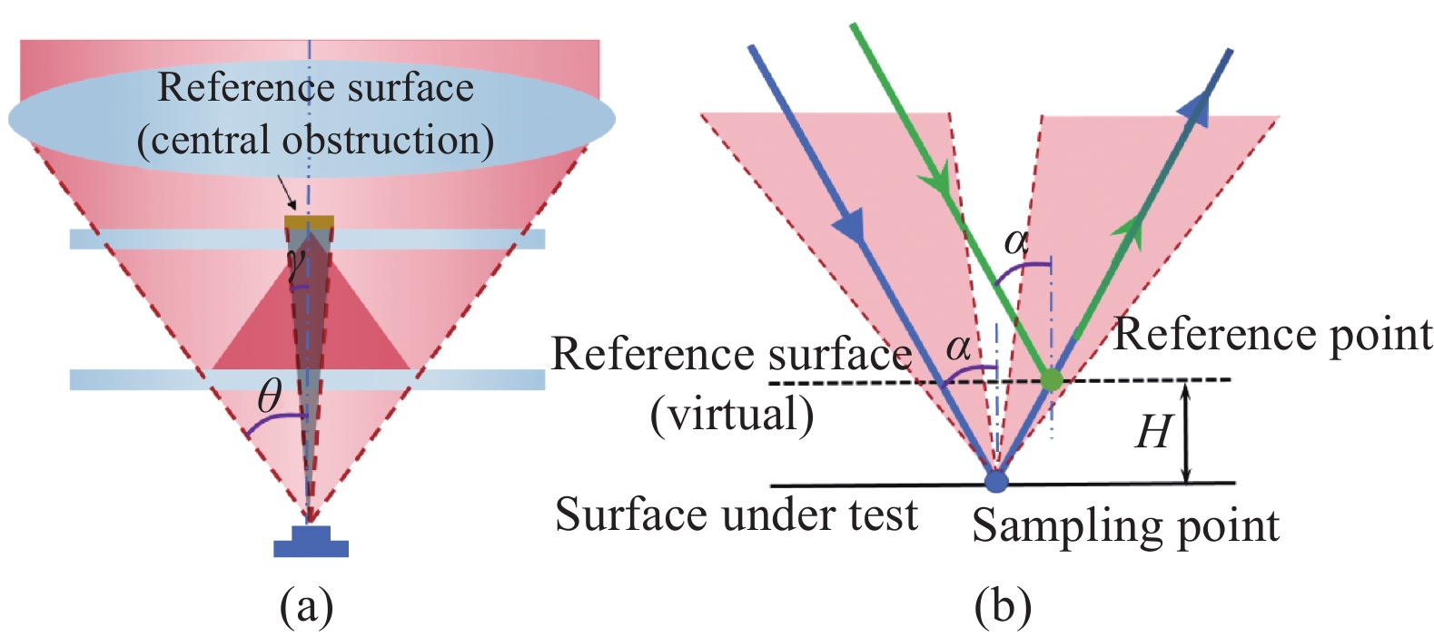
公式(2)中计算光程差时测试光线垂直于待测件,而在白光显微干涉术中,采用的干涉显微物镜通常具有一定的NA。图3(a)所示为Mirau型干涉物镜的孔径角情况,参考板位置的参考面是照明和成像系统中的中心遮拦。因此,有效的NA为环型会聚的光束,参与干涉成像的光束孔径角范围为γ~θ。图3(b)画出了入射角为α的光线的干涉情况,将参考面经过分光镜镜像至待测面附近做分析,假定待测面面和参考面的高度差为H,则参考光线和测试光线的光程差δ为:

Figure 3. NA effect of the Mirau type interference microscope. (a) Effective NA; (b) OPD
公式(9)表明,对于干涉显微物镜中有效NA范围内参与成像的各个入射角度光线,其光程差与光线入射角度余弦呈线性关系。进一步地,干涉显微物镜作用下的光程差是有效孔径内光程差的积分,小于垂直高度差,导致干涉条纹展宽。
上述现象称为干涉显微物镜的NA效应[12-14],可以定义系数C1(<1)表征其对光程的影响。干涉显微物镜主要有3种类型,文中以Mirau型干涉显微物镜为例,Michelson型和Linnik型干涉显微物镜的工作模式与之类似。NA效应在高倍率干涉显微物镜上较为显著,Mirau型物镜由于存在中心遮拦,其作用最为复杂。有相关文献讨论了C1的数学表达形式[12-14],但干涉显微物镜有效NA范围的名义值与实际值存在偏差,通过实验测量获得C1是一种较为有效的手段[13-14]。此外,PZT也存在误差,导致实际步进量σ′偏离名义步进量σ,定义C2为PZT位移的误差系数,则公式(2)可以被修正为:
分析在NA效应和移相器误差的双重作用下,计算形貌的公式(8)存在的误差情况。定义Zc′为存在移相误差情况下按照公式(4)计算得到的粗略形貌,分析其与真实粗略形貌Zc的关系。公式(4)中粗略形貌Zc的求解是计算对比度最佳采样幅数k,再与垂直扫描步长为σ相乘,中间未涉及到光程差的计算,所以Zc的求解与NA效应的影响无关。因而有:
求解粗略形貌Zc主要的误差源为PZT位移误差,即名义步进量σ=λ0/8,但实际步进量是其C2倍。比较公式(4)和(11),尽管扫描步长发生了变化,粗略形貌的求解方式仍然一样,这与常规垂直扫描方式可以变换步长的效果是等效的。也即是只要知道实际的扫描步长,均能准确获得粗略形貌高度。这也与常规垂直扫描求解表面形貌不需要考虑干涉显微物镜的NA相吻合。
精细形貌Zf的求解是通过移相算法求解相位,再转换为光程差,再换成形貌高度。其中需要考虑NA效应的影响因子C1。公式(7)中定义了相位
$\phi $ ,定义NA作用下的综合相位$\tilde \phi $ ,则满足$\tilde \phi = {C_1}\phi $ 。定义$\phi '$ 为移相算法计算获取的相位。相应的,按照公式 (7)计算精细形貌Zf′的表达式为:单独讨论PSI算法,移相量从π/2变为Cπ/2(C=C1C2)的作用,公式(12)的相位计算存在误差,接下来分析计算获得的相位
$\phi '$ 的形式特征。将移相误差对光程差的影响公式(10)引入到白光显微干涉光强的表达式(1)中,即可得到各幅垂直扫描移相干涉图的干涉光强。然后根据公式(5)和(6)即可计算分析7幅法和4M幅法各自的复原相位情况。尽管已知单色光干涉时,7幅法对移相误差不敏感,但此处PSI算法的应用场景为复色光。因为基于理论公式的推导过程较为复杂,文中采用数值模拟的方式分析计算相位复原的情况。PSI算法的测试对象是高度小于λ0/4的台阶,所以数值模拟计算的设置参数如表1所示。
H/nm λ0/nm Δλ/nm γ C σ/nm 100 560 200 1 0.8-1.2 70 Table 1. Parameters for simulation analysis of PSI algorithms
以高度100 nm的台阶为测试对象,高度数据和相位数据的转换不考虑NA效应,所以输入的直接是综合相位
$\tilde \phi $ ,图4(a)为台阶一维轮廓分布;图4(b)为某幅中间位置的扫描干涉图,其中有载频条纹,探测器的量化选用10 byte;图4(c)和(d)分别为7幅法复原的台阶一维轮廓及复原误差;图4(e)和(f)为4M幅法复原的台阶一维轮廓及复原误差。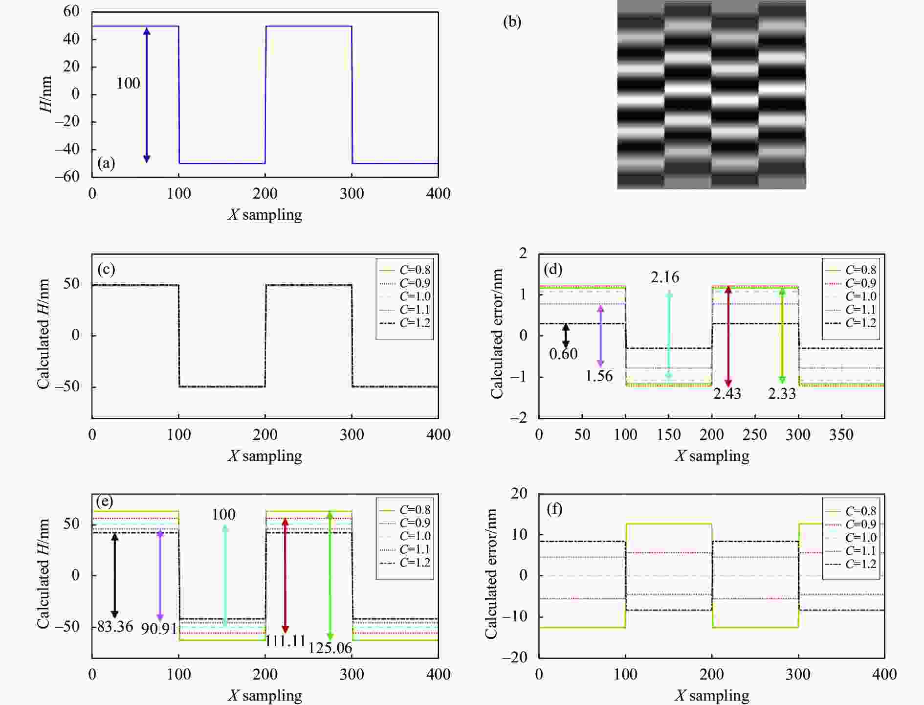
Figure 4. Step profile measurement utilizing the PSI algorithms. (a) Step with 100 nm height; (b) Interferogram; (c) Measured profile utilizing 7-frame algorithm; (d) Measured error utilizing 7-frame algorithm; (e) Measured profile utilizing 4M-frame algorithm; (f) Measured error utilizing 4M-frame algorithm
根据图4(d)显示的数据,当实际扫描步进量分别为名义值λ0/8的0.8、0.9、1.0、1.1、1.2倍时,采用7幅法复原台阶高度的计算误差非常小,分别偏差2.33、2.43、2.16、1.56、0.60 nm,图4(c)中7幅法复原的台阶高度与名义值100 nm十分接近,在宽带光条件下,7幅法仍然对移相误差不敏感,即
$\phi '{\text{ = }}\tilde \phi $ 。图4(e)中,4M 幅法复原的台阶形貌与图4(a)的原始形貌相比做了整体的缩放或拉伸,复原的台阶高度分别为125.06、111.11、100、90.91、83.36 nm,分别是名义高度值100 nm的1/0.8、1/0.9、1/1、1/1.1、1/1.2倍。也即是当存在移相误差时,4M算法复原出的相位结果是名义相位的1/C倍,即$\phi '{\text{ = }}\dfrac{{\tilde \phi }}{C}$ 。因此,面向NA效应(C1)和移相器误差(C2)两种移相误差的影响,7幅法和4M幅法各自计算的精细形貌为:
继而,考虑公式(11)中求解获得的粗略形貌Zc′和实际粗略形貌Zc的关系,待复原的表面形貌Z与求解获得的形貌的关系式为:
因此,采用垂直扫描移相计算微观形貌,首先要求移相器位移准确,移相器误差将影响形貌复原结果。采用7幅法计算精细形貌,尽管相位计算时其对移相误差不敏感,但物镜的NA效应需要被纳入考虑;而采用4M法的精细相位误差形式恰好与物镜的NA效应对条纹展宽的影响相一致,在从精细相位转换为精细形貌时相互抵消。准确计算物镜NA效应的影响因子C1比较困难,因而公式(15)中采用7幅法计算求解微观形貌比较难以实现。采用4M法计算求解微观形貌,物镜NA效应的影响因子C1没有影响,移相器误差C2对于粗略形貌和精细形貌的影响相同,可以通过测量已知高度的标准台阶,比较测量高度和标准高度,完成对C2的标定。综上,采用基于对比度变化重心提取的VSI算法和4M幅PSI算法计算形貌数据,无需在移相量设置时考虑引入物镜NA的影响,只要精确知道PZT的扫描步进量,即可准确地复原形貌数据。
-
为了验证所提方法对垂直扫描移相误差的校正能力,采用校准高度为(459.8±3.0) nm的标准台阶板(BKUKER, S/N1612-270)作为样品, 在自研的白光显微干涉仪上进行测试。采用闭环伸长量250 μm,闭环线性度0.03%的PZT(PI, P-725),搭载数个倍率的干涉显微物镜进行测量。台阶板样品信息如图5所示。

Figure 5. Photos and figures of the step height standard
5倍干涉显微物镜的NA为0.1,NA效应的较小,认为此时C1=1。为了确定低相干垂直扫描干涉测量的中心波长λ0,先假定一个初始值,并据此设定扫描步长为λ0/8,采集垂直扫描移相低相干干涉图序列,提取在最大对比度位置附近相邻的8幅干涉图,用7幅算法分别计算前7幅图和后7幅图的相位,再计算二者相位差,根据相位差偏离π/2的情况修正假定的λ0值,最终确立λ0为550 nm,相应的扫描步长为68.75 nm。
为了引入NA效应的影响,更换采用20倍干涉显微物镜,其NA为0.4,NA效应的影响因子C1<1。如仍以扫描步长68.75 nm进行垂直扫描移相采图,则受NA效应的影响,移相量偏离π/2。按照前述采集相邻两组7幅图计算相位差的方式,实验调试得到C1=1.043,即扫描步长为71.71 nm对应π/2移相量。但为了仿真实验的真实情况,不对NA效应进行校正,并且为了进一步引入PZT误差,人为设置扫描步长偏离λ0/8。如表2所示,实际的扫描步长σ′均偏离了71.71 nm,相当于既有NA效应的影响因子C1,又有PZT误差的影响因子C2。需要说明的是,由于实验采用的PZT闭环控制时线性度较好,实际的扫描步长是已知的,将其代入到公式(15)中计算形貌分布,然后对台阶形貌上所有水平方向轮廓曲线分别计算台阶高度再求平均值得到每次测量的台阶高度数据。从一根水平轮廓线上提取台阶高度的计算依据ISO5436-1:2000规定的W/3方法。表2给出了不同的扫描步进量,VSI算法采用基于对比度变化的重心提取法,PSI算法分别采用4M幅法和7幅法两种PSI算法,计算得到的台阶高度数据H′。图6给出了在扫描步长为λ0/8条件下的台阶形貌和中间位置的一维轮廓曲线。
σ′ H′ 4M-frame method/nm 7-frame method/nm 0.9×λ0/8 459.2 455.8 0.95×λ0/8 458.8 454.4 1×λ0/8 460.4 454.7 1.05×λ0/8 459.6 453.3 1.1×λ0/8 459.4 453.9 Table 2. Calculation results of step height with different scanning interval
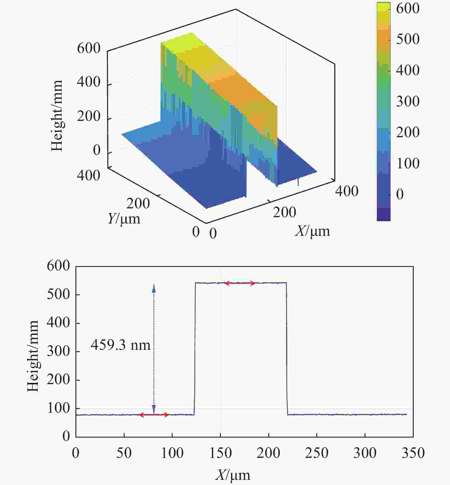
Figure 6. Calculated topography of the step height standard using 20× interferometric microscopy (4M-frame method)
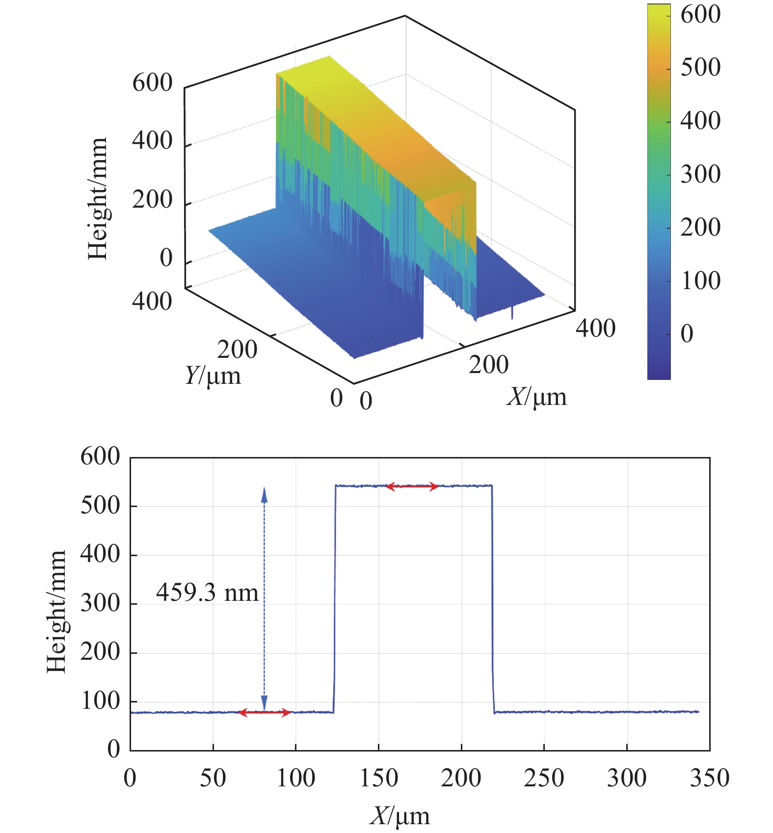
更换采用50倍干涉显微物镜,其NA为0.55,NA效应的影响因子更小。仍然采用λ0/8扫描步长,此时相当于仍未对NA效应引入的移相误差做校正,也即是移相量进一步偏离π/2。计算得到的形貌数据如图7所示,仍可准确地复原台阶高度。

Figure 7. Calculated topography of the step height standard using 50× interferometric microscopy (4M-frame method)
因而,此次实验分别采用20倍和50倍干涉显微镜检测了校准台阶高度为(459.8±3.0) nm的标准台阶板。采用λ0/8扫描步长时,没有考虑到NA效应对于移相量偏离π/2的影响,但采用基于对比度变化重心提取的VSI算法和4M幅PSI算法计算形貌数据,形貌复原结构仍然十分准确。此外,人为设置扫描步长偏离λ0/8,但只要准确知晓PZT实际的步长,也可以准确复原形貌。因此,对于PZT误差的影响,可以通过检测已知高度的台阶,对PZT的线性度进行标定,从而准确得到PZT的实际移动量。
-
针对白光显微干涉术垂直扫描移相的移相误差问题进行了理论分析,将其归类为干涉显微物镜NA效应的影响和移相器误差两种类型。分析了移相误差对于三维形貌复原算法中VSI算法和PSI算法的影响。结果表明:宽带作用下,PSI算法中的7幅算法延续了其在单色光情况下对移相误差不敏感的优越表现,4M幅法产生的精细相位误差形式恰好与相位转换为形貌高度信息时所需要考虑的干涉显微物镜NA效应的影响因子相抵消。PZT位移误差可以通过测量已知高度的台阶进行标定去除。因而,在白光显微干涉术中优选基于对比度变化重心提取的VSI算法和4M幅PSI算法计算形貌数据,可以不用考虑计算NA效应影响因子的复杂过程,即不需要修正扫描步长以满足移相量为π/2,只需确保PZT位移准确,即可准确获得三维形貌数据,这有效地保证了低相干垂直扫描算法的可操作性和鲁棒性。
Calibration method of the phase-shifting error for the topography measurement utilizing white light interferometric microscopy
doi: 10.3788/IRLA20220050
- Received Date: 2021-11-20
- Rev Recd Date: 2022-01-10
- Accepted Date: 2022-03-25
- Available Online: 2022-08-13
- Publish Date: 2022-08-05
Fund Project:
National Key Research and Development Program of China(2019 YFB2005500);National Natural Science Foundation of China (62175107)
-
Key words:
- phase-shifting error /
- step /
- topography measurement /
- white light interferometric microscopy
Abstract: Sequence of low coherence interferograms were captured during the vertical scanning of the interferometric microscope in the measurement procedure of the white light interferometric microscopy, and thus the topography of the surface under test was retrieved through determining the locations where the optical path difference (OPD) was zero in the envelope of the correlogram. The calculations of the topography for the micro-structures were composed of the vertical scanning interferometric (VSI) algorithm determining the coarse map and the phase-shifting interferometric (PSI) algorithm retrieving the fine map. Usually, the vertical scanning step was set as one eighth of the central wavelength, but the phase-shifting departures from π/2 inevitably due to the phase shifter error as well as the numerical aperture (NA) effect of the interferometric microscope. In this manuscript, the center-of-gravity solving of the visibility curves was adopted as VSI algorithm, and the 4M-frame method as well as the 7-frame method were both utilized as PSI algorithm respectively. The effect of the phase-shifting error on the topography measurement adopting the three above mentioned methods was discussed. Both theoretical derivations and simulation analysis demonstrate that the 7-frame method was insensitive to phase-shifting errors even under the low coherence illuminations. The fine phase error induced by phase-shifting error utilizing the 4M-frame method was by lucky coincides the form of the NA effect increasing the fringe spacing, and they were cancelled out during the transform from the fine phase to the topography. Therefore, adopting the center-of-gravity method as VSI algorithm and the 4M-frame method as the PSI algorithm, the phase-shifting errors arising from NA effect can be ignored, and the topography can be calibrated confronting the phase shifter error through measuring a certificated step standard in advance. A step height of 460 nm was measured utilizing the proposed method, and the topography demonstrate that it was both accurate and robustness.


 DownLoad: