


-
平衡零拍探测技术能够直接测量电磁场模式中与相位相关的正交场噪声,可以表征电磁场模式的量子态特征并测量光场的正交分量噪声,是精密测量领域及量子信息等领域中关键器件。自20世纪80年代以来,平衡零拍探测已经在连续变量量子信息[1-2]、相干光通信[3-4]、微弱信号测量[5]、量子通信[6]等方面有着广泛的应用。在平衡零拍探测中,信号光与强的本振光(Local Oscillator,LO)在一个50/50分束镜上进行干涉,分束镜的两个输出光场由两个高效率的光电二极管接收,随后它们产生的光电流进行相减,理想情况下相减后的光电流与信号场的正交分量成正比,相应的相位由LO光的相位决定,当信号光为真空场时,平衡零拍探测测量的是真空涨落[7]。
针对不同探测需求,多种类型的平衡零拍探测器(Balanced homodyne detector, BHD)已被研发,其响应频段及增益特性不尽相同。针对MHz频段连续变量压缩态及纠缠态光场的噪声谱测量,山西大学团队研发了增益达50 dB,共模抑制比达76 dB的平衡零拍探测器,其在1~5 MHz范围内可以实现高增益高效率探测,然而其带宽较窄[8];针对量子密钥分发,需要百兆以上带宽的平衡零拍探测器被研发[9];在量子通信和量子层析等领域,时域脉冲平衡零拍探测器作为测量编码密钥信息脉冲光场量子态的关键器件[10-11];针对量子存储,快速响应平衡零拍探测器已经研发[12]。在相对高频段探测中,本振的激光强度噪声位于散粒噪声极限(SNL),其激光强度噪声对信号光光场噪声探测影响很小。然而在音频及以下频率,尤其在1 Hz以下的频段,LO的激光强度噪声通常高于SNL[13],常规的测量系统在低频段内进行探测极易受到环境温漂、机械振动、电磁环境变化等因素的干扰,这就需要所设计的平衡零拍探测器在低频段具有低电子学噪声、高稳定性和高增益等特性。
在低频段,针对地基引力波探测所在的几赫兹和几千赫兹频段,在2008 年,LIGO实验室N. Mavalvala团队在发展音频段平衡零拍探测器基础上,实现了1 kHz 处量子压缩态光场的噪声谱测量[14],并随后在地基引力波探测装置LIGO以及GEO600中实现了量子增强引力波探测灵敏度的提升[15]。在2012 年, Stefszky 等在10 Hz处测到了量子压缩光场的噪声谱[16]。在2007年,Vahlbruch等[17]利用Hz级平衡零拍探测装置在1 Hz处测量了量子压缩光场噪声谱;所以基于低噪声光电探测可以进行低频段噪声谱的测量。
然而,空间引力波探测的频段在0.1 mHz~1 Hz频段范围,相较于地基引力波其探测频率更低,能够探测到超大质量黑洞合并、超紧凑双星等波源[18]。极低频率的引力波具有比地球本身更大的波长,受地面震动和引力梯度噪声的影响,这些极低频范围的引力波源即使是最先进的地面探测器也无法探测到,因此需要在太空中部署更大的装置来实现探测[19-21]。由于空间中的激光干涉仪臂长较长,频率较低,因此对激光在低频段噪声的抑噪要求更高[22-23]。不同空间引力波探测计划在轨道半径、激光系统、无拖曳系统等关键技术方面大同小异,以天琴空间引力波探测计划为例,其对激光系统的主要要求为:激光波长为 1064 nm;输出功率大于4 W;相对强度噪声低于10−4 /Hz1/2;频率噪声低于10 Hz/Hz1/2;指向不稳定度小于等于10 nrad;皮瓦级激光干涉测量精度要求为1 pm/Hz1/2等[24]。针对空间引力波探测中不同模块组件的探测需求,所需探测器类型也随之不同;例如针对空间探测器指向控制及抑制激光指向噪声的需要,Shubhashish Datta等人研发出测量带宽在20 MHz的四象限探测器进行反馈控制[25],中国科学院力学研究所研制出响应在0.1 MHz~1 Hz频段的四象限探测器并将激光抖动噪声降低至小于4 nrad/ @10 mHz;对于抑制激光强度噪声,Patrick Kwee等人研发出多光电二极管阵列来探测激光噪声并进行反馈降噪[26];针对皮瓦级激光干涉测量需求,中国科学院力学研究所研发了单光电二极管的弱光探测器[27];对于弱光激光干涉噪声分析及差拍信号提取分析,需要平衡探测器抑制激光经典信号并提取干涉或差拍信号[28-29];然而,目前商用探测器没有在空间引力波探测频段进行噪声表征;针对空间引力波探测的极低频段的平衡零拍探测系统的研发及其性能评估仍有待探究。
文中基于自减电路及跨阻放大电路进行整体电路设计。通过选定低噪声运算放大器芯片、低温漂系数元件;采用高稳定偏压系统、低噪声供电系统;并且结合电磁屏蔽、以及主动温控等技术手段,实现了高增益低噪声平衡零拍探测系统的研制。在此基础上,搭建1064 nm波长的测量光电探测器性能的实验系统。当无外界光场时,平衡零拍探测器输出电子学噪声信号;加外界光场,光场的强度噪声经光电管探测及电路放大转变为电压信号。采用高精度的数字万用表对探测器电子学噪声信号进行高精度的数据采集,结合快速傅里叶变换法以及对数轴功率谱密度法,实现对0.05 mHz~1 Hz频段的探测器电子学噪声和增益的测量分析;实现对平衡零拍探测系统的增益等性能的评估测试,从而完成对高增益低噪声平衡零拍探测系统的综合评估,为空间引力波探测中激光强度噪声表征及抑制等方面提供关键器件支撑。
-
平衡零拍探测技术可以有效抑制共模信号,放大差模信号,其探测原理图如图1所示[30-31]。

Figure 1. Schematic diagram of balanced homodyne detection
信号光场与LO光场在一个50/50分束器上干涉。干涉后输出两个光场分别为
$\hat c$ 和$\hat d$ :式中:
$\hat a_s^ + $ 和${\hat a_s}$ 分别为信号光场的产生和湮灭算符;$\hat a_L^ + $ 和${\hat a_L}$ 为本振光场的产生和湮灭算符;${\eta _1}$ 和${\eta _2}$ 表示PD1和PD2的量子效率;$\theta $ 为信号光场${\hat a_s} = \alpha + \delta {\hat a_s}$ 与LO光场${\hat a_L} = \beta + \delta {\hat a_L}$ 间的相位差,在实验中,可以通过改变本振光光路上带压电陶瓷(PZT)的镜子来实现对相位差$\theta $ 的控制,然后通过光电探测器测量光场$\hat c$ 和$\hat d$ 。由于LO光场强度远大于信号光场的强度,即$\beta \gg \alpha $ 。并且利用$\delta {\hat X_a}(\theta )$ 和$\delta {\hat X_b}(\theta )$ 来表示场涨落项${\hat a_s}$ 和${\hat a_L}$ 在相对相位$\theta $ 处的正交涨落算符,那么两个光电管的光电流可表示为:在实际的平衡零拍探测中,除了量子效率存在差异外,两个光电探测器之间还存在着增益因子和电子元件上的差异,这些可以用探测器的共模抑制比表示。由除光电二极管之外的电子元件差异引起的不平衡项用
${\eta _{imb}}$ 表示。不平衡项${\eta _{imb}}$ 被添加到平衡零拍探测器的一个臂上,用于表示探测器其他电子元件引起的不平衡。因此,这两个光电探测器上的光电流的差值可表示为:式中:
$G = {\eta _2}{\eta _{imb}}/{\eta _1}$ 为不平衡因子,其表征了BHD的不平衡元素。通过取光电流${\hat I_ - }$ 的平方,可以计算信号光噪声方差$V$ :当阻档Signal光场时,Signal光场对应于真空状态,此时方差
$V\left( {{{\hat X}_a}(\theta )} \right)$ 是光场SNL。将信号光场注入平衡零拍探测系统,测量微弱信号光场的噪声谱的测量值可表示为:如果BHD达到平衡,即不平衡因子G等于1,并且LO光场的强度噪声达到SNL,则公式(5)可简化为:
此时信号光场的噪声测量值等于实际值。否则,测量值和实际值会存在一个偏差E,E取决于平衡零拍探测的共模抑制比和LO光场本振的强度噪声,由下式给出:
依据公式(7),计算可得探测偏差随本振光噪声及不平衡度的变化关系,其中图2(a)为信号光场正交振幅位相噪声方差为10时,测量偏差随LO光场的强度噪声和平衡因子G的变化关系。当不平衡度为0 dB时,既BHD的共模抑制比很好时,所引起的探测偏差0;如果不平衡度不为0 dB时,随本振光噪声的增加,引起逆向测量误差。

Figure 2. Relation diagram of detection deviation with local vibration noise and unbalance degree
图2(b)为信号光场正交振幅噪声方差为0.1时,测量偏差随LO光场的强度噪声和平衡因子G的变化关系。当不平衡度为0 dB时,即BHD的共模抑制比很好时,所引起的探测偏差为0;如果不平衡度不为0 dB时,随本振光噪声的增加,引起正向测量误差。
只有当BHD具有较好的平衡特性以及消除LO光的经典噪声才能对信号光场的正交振幅和位相噪声进行精密测量,计算可得:
式中:
${\hat X_s} = \left( {{{\hat a}_s} + \hat a_s^ + } \right)/2$ 和${\hat Y_s} = \left( {{{\hat a}_s} - \hat a_s^ + } \right)/2 i$ 为量子态的正交振幅算符和正交位相算符。分析可知,当相位差$\theta = 0$ 时,BHD测量Signal光场量子态的正交位相分量上的噪声方差$(\Delta \langle {\hat Y_s}\rangle ){{\text{ }}^2}$ ;当相位差$\theta = \pi /2$ 时,测量Signal光场量子态的正交振幅分量上的噪声方差${(\Delta \langle {\hat X_s}\rangle )^2}$ ,若挡住Signal光场,即输入端口为真空场,测量的是真空场的量子噪声起伏[32]。 -

Figure 3. AC output noise model of BHD
该BHD噪声模型是基于跨阻电路的噪声分析建立的。图中两个虚线框内为两臂光电二极管的等效电路。BHD的电子学噪声[34]主要包括四种相互独立的噪声:(1)运算放大器反馈电阻的热噪声;(2)由PD暗电流引起的散粒噪声以及PD并联电阻的热噪声;(3)运算放大器的输入电流电压噪声。
(1)反馈电阻
${R_f}$ 的热噪声可以表示为:式中:
$K$ 为玻耳兹曼常数;$T$ 为热力学温度;$\Delta f$ 为单位测量带宽;${Z_s}$ 为跨阻抗放大电路的增益阻抗;$f$ 为分析频率;${C_f}$ 为跨阻电路的反馈电容;$||$ 表示两个元件之间的并联关系。在BHD中,采用${R_f}$ 为100 kΩ,温漂系数为1 ppm(1ppm=10−6),${C_f}$ 为82 μF,$f$ 为1 Hz,计算可得${e_{{R_f},Thermal}} = 39.9\; {\rm{nV}}/\sqrt {{\rm{Hz}}}$ 。(2)光电二极管所引起的BHD的电子学噪声,包括暗电流引起的散粒噪声以及并联电阻产生的热噪声,假设
${I_{dk1}}$ 和${I_{dk2}}$ 分别为PD1和PD2的暗电流,则它们引起的散粒噪声$\Delta {i_{{\rm{PD}}1,Dark}}$ 和$\Delta {i_{{\rm{PD}}2,Dark}}$ 为:式中:e为电荷量。采用C30642光电二极管,暗电流为10 nA,则
$\Delta {i_{PD1,Dark}}$ 和$\Delta {i_{PD2,Dark}}$ 为0.566 nA,所以与反馈电阻产生的热噪声相比可以不予考虑。PD1和PD2的并联电阻产生的热噪声可表示为:式中:
${R_{d1}} = {V_{bias}}/{I_{dk1}}$ 和${R_{d2}} = {V_{bias}}/{I_{dk2}}$ 为PD1和PD2的并联电阻。根据上式可知,加载光电二极管上的偏置电压${V_{bias}}$ 的噪声将直接影响光电二极管并联电阻产生的热噪声,传统7805输出5 V电压的偏差为±3%以上,输出电压温漂为0.8 mV/℃,这将直接导致热噪声的增加,所以必须采用低温漂及输出电压稳定的偏置供电电压。(3)运算放大器所引起的BHD电子学噪声,包括运算放大器输入电流和电压噪声。当运算放大器的输入电流噪声为
${I_{noi}}$ 时,则输入电流噪声经过运算放大后器转化后的电压噪声和来自运算放大器输入电压噪声${e_{in}}$ 为:式中:
$\left| {{Z_n}} \right|$ 为运算放大器的电压噪声增益;这里$ {Z_d} $ 表示跨阻放大电路的输入阻抗。Zd可以写为:式中:
${C_{d1}}$ ,${C_{d2}}$ 和${C_{in}}$ 分别为PD1和PD2的结电容以及放大电路的输入电容。由于构成BHD的电子学噪声的噪声都是相互独立,因此BHD的电子学噪声可以表示为:
将公式(9a)和公式(13b)代入公式(15)中,则总的电子学噪声能够表达为:
所以,在较低频段,探测电路的电子学噪声的主要来源是反馈电阻
${R_f}$ 的热噪声和运放的输入电压噪声。 -
根据平衡零拍原理进行电路设计,图4为所设计平衡零拍探测器原理图,首先选择12 V输出的锂电池给定制基准电压芯片供电,以便降低电源噪声对探测器的影响;定制电压基准芯片输出的正负5 V作为光电二极管的偏置电压,其电压稳定性优于10 ppm,可以有效抑制偏置电压不稳定引起的光电流不平衡的影响,并降低探测器整体电子学噪声;采用Excelitas Technologies公司的型号为C30642的光电二极管,暗电流为10 nA;利用自减电路形式,将两个光电转化效率相近的光电二极管串联,其自相减信号作为集成运算放大器的输入信号,以提高探测器的饱和功率和共模抑制比,也可以有效抑制光电转换效率不一致引起的光电流不平衡;进一步为了实现温度不敏感,提高稳定性,采用低噪声运算放大芯片LF356 N作为主放大芯片,其增益带宽积为5 MHz;反馈电阻选取阻值为100 kΩ的低温漂系数精密电阻;反馈电容选取82 pF,主要用于优化放大频谱的平坦度和通过补偿相位延迟来抑制自激振荡;自减电信号经过第一级放大后通过由集成芯片LT1028 ACN8构成的跟随器,起到缓冲及隔离作用。
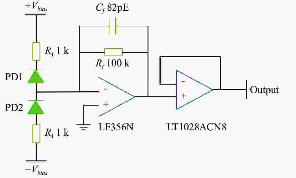
Figure 4. Schematic diagram of the balanced homodyne detector
将图4中的参数以及芯片LF356 N的输入电压噪声ein (110 nV/Hz1/2@1 Hz)代入公式(16)中,可以计算出总电子学噪声为1.27×10⁻⁷ V/Hz1/2,低于天琴计划对激光强度噪声10−4 V/Hz1/2,并略低于实验测量结果,实验与理论计算的误差可能是计算过程中忽略了一些小项引起的,符合设计预期,满足空间引力波探测中激光噪声探测。
针对空间引力波探测频段(0.1 mHz~1 Hz)内噪声探测及表征分析需求,搭建了测量探测器性能的实验装置,如图5所示,采用全固态激光光源输出波长为1064 nm,最大功率2 W的激光,图中,FI为隔离器; HWP为半波片;L为透镜;HR为 1064 nm高反镜;PBS为偏振分束镜;PD为光电二极管探测器;SA为频谱分析仪;DMM为8位半数字万用表。输出激光通过光隔离器后入射到一组半波片和偏振分光棱镜(PBS),通过旋转半波片改变入射光的偏振用来调节PBS的分光比,从而控制进入BHD的总光功率。利用第二组半波片和PBS,调节BHD两臂入射光功率,使分出的两臂光功率严格相等。两臂光经过导光镜和聚焦透镜,将光完全导入平衡零拍探测器的两个光电极管。

Figure 5. Schematic of the experimental setup for measuring performance of photodetector
然而,目前低频商用谱仪最小可分析频率为375 mHz,无法对空间引力波探测的全频段进行噪声评估及测量,这就需要傅里叶变换等算法将时域信号转化为频域信号,所以首先需要解决的是对BHD输出端的低噪声采集,选取是德科技的8.5位数字万用表(DMM)进行数据采集,BHD输出电压信号经屏蔽线缆接到高精度万用表接线柱,采集数据时,数字万用表设置量程为10 V,其最大分辨电压100 nV。通过自行编写的LabVIEW程序对DMM进行操控并记录数据,需要指出的是所有系统需要大约1~2 h预热稳定才能进行数据采集分析,以消除测试系统引起的误差。
其次,根据Nyquist-Shannon采样定理,时域信号转换到频域信号后,频谱中最大分析频率
${f_{\max }}$ 为数据采样率${f_s}$ 的一半,频谱最小分析频率${f_{\min }}$ 为数据采样率${f_s}$ 除以总采样点数N。空间引力波探测主要聚焦于0.1 mHz~1 Hz频段范围内的引力波信号,为了采集并且表征此低频段的激光强度噪声,需要长时间采集大量的样本数据,所以时域数据采样率至少为2 S/s。如果以2 S/s采样率进行数据采集,若想满足引力波探测全频段噪声谱分析需求,那么频谱最小分析频率需为0.1 mHz,采样时间至少为2.8 h。为了更好地对 0.05 mHz~1 Hz 频段噪声分析以及避免数据量大影响数据处理速度,实验中采样率设置为2 S/s,采样时间设置为5 h,这对于数据采集硬件长时间的稳定性与精度提出了相当高的要求。对于传统FFT算法,由于数据量大且频段较宽,这就导致频谱结果在低频端(接近0.1 mHz 端)曲线较为平滑,在高频端(接近1 Hz 端)曲线变得密集不易分辨频谱细节,也就是“拖尾现象”[35]。然而WOSA法较好的解决了上述问题,但在频段衔接处线条不平滑,出现偏差,还需进行频谱校准;之后德国Michael Tröbs[35]等人发展了对数频率轴功率谱密度算法(Logarithmic frequency axis Power Spectral Density,LPSD),其对于不同傅里叶分析频率采用不同的频率分辨率进行数据处理,很好解决了 WOSA 方法在分段衔接处不平滑的不足,但针对空间引力波探测的特殊要求仍需对分段重叠的影响进行评估,并进行频谱估计校正优化。通过LabVIEW程序编写的LPSD及传统FFT算法程序对采集信号进行实时处理并获得噪声谱分析结果。
为了更好评估平衡零拍探测系统在空间引力波探测频段的性能,拓展了探测器性能测试频段,首先利用商用频谱分析仪(Rohde & Schwarz FSW8)测量其在2~500 Hz频段噪声特性;频谱仪分辨率带宽(RBW)和视频分辨率带宽(VBW)设置为10 Hz和1 Hz。
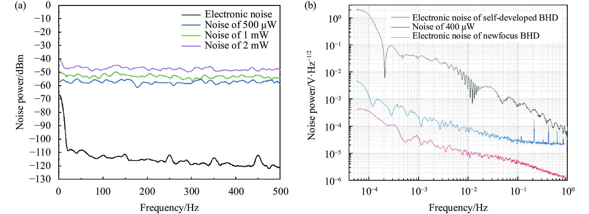
实验结果如图6(a)所示,图中数据从下往上依次为BHD的电子学噪声以及入射光分别为500 μW、1 mW 以及2 mW的噪声曲线,由于频谱仪存在低频噪声,致使低频段噪声干扰探测器低频段噪声特性评估,从图6(a)中可知所研发BHD的电子学噪声在−110 dBm以下,当入射光功率为500 μW时,自研BHD增益到达50 dB以上,已经满足激光噪声的探测需求而且探测器在增益在2~500 Hz范围增益比较平整。

Figure 6. BHD performance test results. (a) Performance results of the BHD developed in the 2-500 Hz frequency band; (b) Performance test results of the developed BHD in 0.05 mHz-1 Hz band. The sampling rate of the high-precision multimeter is 2 S/s, the sampling time is 5 h, and the data overlap rate of LPSD processing is 0.3
进一步,采用高精度的8.5位DMM采集数据,结合快速傅里叶变换法和对数轴功率谱密度法评估BHD的低频性能。考虑到测量0.1 mHz~1 Hz频段时,需要5 h的测量时间,且光电二极管在较高激光长时间照射时,会引起光电二极管性能变化导致在测量时引入额外误差,选择了光功率和500 μW相近的400 μW入射光进行低频段噪声探测。
实验结果如图6(b)所示。探测器的电子学噪声水平直接影响激光噪声测量准确性及抑制激光噪声的上限,首先测量自研BHD的电子学噪声以及商用BHD(Newfocus,2117)在设置增益为3×10⁴ V/W时的电子学噪声,分别为图6(b)中最下面红色曲线和中间蓝色曲线;从结果可知自研BHD在0.05 mHz~1 mHz时电子学噪声谱密度低于4.32×10⁻⁴ V/Hz1/2;在1 mHz~1 Hz内的电子学噪声谱密度为3.6×10⁻⁵ V/Hz1/2以下,低于天琴空间引力波探测计划对于激光强度噪声要求(1×10−4 V/Hz1/2)。并且只有探测器的电子学噪声低于激光噪声时,探测器才可以真实探测到激光噪声。因此,自研探测器可以应用于该频段的激光光源噪声表征和评价。
另外,自研BHD的电子学噪声明显优于商用BHD,在1 mHz~1 Hz内,商用BHD的电子学噪声高于自研BHD电子学噪声一个数量级。对于自研BHD,当入射光功率400 μW激光时,测量得到BHD在0.1 mHz~1 Hz内的电压噪声谱密度增益达到20 dB以上,对应功率噪声谱密度达到40 dB以上,并且测得激光强度噪声在1 mHz时为3.6×10⁻² V/Hz1/2,在低频段完成对激光强度噪声的表征。
-
文中的主要基于自减电路及跨阻放大电路进行整体电路设计,并且在此电路基础上简要分析了BHD的噪声,在较低频段,探测电路的电子学噪声的主要来源是反馈电阻
${R_f}$ 的热噪声和运放的输入电压噪声,进一步实现了面向空间引力波高增益低噪声平衡零拍探测系统的研制。采用高精度的数字万用表,结合快速傅里叶变换法以及对数轴功率谱密度法,实现对0.05 mHz~1 Hz频段的探测器电子学噪声的测量分析,实测电子学噪声谱密度在在1 mHz~1 Hz的频率范围低于3.6×10⁻⁵ V/Hz1/2,并且低于天琴空间引力波探测计划对于激光强度噪声要求(1×10−4 V/Hz1/2);在入射400 μW光场时,探测器在此频段增益达到20 dB以上,在1 mHz时激光强度噪声为3.6×10⁻² V/Hz1/2;采用高分辨率频谱分析仪,实现对平衡零拍探测系统的增益、线性度、带宽等性能的评估测试,为空间引力波探测中激光强度噪声抑制以及探测低频段压缩态光场等方面提供关键器件。
Research on low noise balanced homodyne detection system for space-based gravitational wave detection (Invited)
doi: 10.3788/IRLA20220300
- Received Date: 2022-02-20
- Rev Recd Date: 2022-03-15
- Available Online: 2022-10-12
- Publish Date: 2022-07-05
Fund Project:
National Key Research and Development Program of China(2020YFC2200402);National Natural Science Foundation of China ( 62027821, 62035015, 12174234, 11874250);Key R&D Plan of Shanxi Province(202102150101003, 201903D111001);Shanxi Sanjin Distinguished Professor Program
-
Key words:
- space-based gravitational wave detection /
- balanced homodyne detection /
- vacuum noise /
- LPSD
Abstract: The space-based gravitational wave detection frequency band is located in the range of 0.1 mHz-1 Hz, because the gravitational wave source information with larger characteristic quality and scale is contained in the aforementioned frequency band. At present, large-scale laser interferometer space-based gravitational wave detection projects based on different sizes and space orbits have been gradually implemented. It should be emphasized that the laser intensity noise and frequency noise should be suppressed in the laser source system of the interferometer. Moreover, as the first level device of laser noise characterization and suppression, the performance of photoelectric detection will directly affect the effect of laser noise suppression. First of all, on the basis of selecting low noise chip and high stable bias system, the whole circuit was designed by self-reducing circuit and transimpedance-amplifying circuit. In addition, in electromagnetic shielding, low temperature drift factor element, low noise power supply and active temperature control and other technical means, realize the development of high gain and low noise balanced homodyne detection system. Finally, the gain and bandwidth of the photodetector were evaluated and tested by combining the fast Fourier transform method and the number line power spectral density algorithm, and the intensity noise of the laser was detected and characterized in the 0.05 mHz-1 Hz band by using the detector. The experimental results show that the electronic noise spectral density of the balanced homodyne detector is less than 3.6×10⁻⁵ V/ Hz1/2 in the frequency range of 1 mHz-1 Hz, which is less than the noise requirement of the laser source for space-based gravitational wave detection. When the incident light power is 400 μW, the gain of the balanced homodyne detection system is measured to be more than 40 dB in the frequency range of 0.1 mHz-1 Hz. What’s more, the spectral density of laser intensity noise is 3.6×10⁻² V/ Hz1/2 at 1 mHz. Low noise photoelectric detection and laser intensity noise characterization are achieved, which provide key device support for laser intensity noise characterization and suppression in space-based gravitational wave detection.


 DownLoad: