


-
“资源一号”卫星(即中巴合作的CBERS卫星)主要服务于陆地资源普查、矿产勘测及农林业等需求[1]。“资源一号”04A星于2019年12月20日在太原卫星发射中心成功发射,目前已成功在轨运行两年多。该卫星是新一代中巴地球资源卫星,星上主载荷分辨率从04星的5 m提升至2 m,相机幅宽从04星的60 km提升至92 km。为实现高分辨率大幅宽的成像需求,04A星上可见光相机采用三反离轴式光学系统形式。
随着光学加工技术进步、光学系统装调能力提升,离轴式光学系统在光学遥感器中的应用越来越广泛。印度的Carto Sat-1立体测绘卫星、美国的QuickBird卫星、英国的Topsat卫星、国内的资源三号卫星多光谱相机、5 m光学卫星可见近红外相机、高分七号卫星等均采用了离轴式光学系统,应用领域涉及到立体测绘、对地观测、天文观测、空间目标探测等。离轴式光学系统大多采用卧式安装方式,该方式具有较好的力学环境适应性,对地面光学系统装调、系统集成测试等方面均具有较好的适应能力。04A星上可见光相机由于受空间尺寸限制只能采用立式安装方式,该安装方式除了克服严酷的发射环境,还需要消除地面光学系统水平装调带来的重力影响,因此为了保证遥感相机入轨后具有良好的成像质量,相机需要具有较好的力学特性和重力卸载特性。
为克服离轴式光学系统立式安装不利因素,文中从高稳定性主承力框、光学反射镜支撑形式及系统集成隔振技术等方面提出了一种适应立式安装的光机结构设计。
-
可见光相机采用的三反离轴式光学系统具有大视场角、低畸变的优点,光学系统焦距2210 mm,视场角8.8°,在71.4 lp/mm空间频率下光学系统MTF达到0.40。主镜、次镜和三镜均为非球面反射镜,通过平面反射镜将光路折射到焦平面,光学系统采用无中间像形式,光学系统构型如图1所示。

Figure 1. Off-axis TMA optical system
可见光相机主、次镜镜间距为790 mm,反射镜通光口径属于中等口径,具体尺寸如表1所示,反射镜面形精度要求较高,在检测波长λ=632.8 nm下,反射镜的面形精度(RMS)要求如表2所示。
Mirror type X-direction effective
passing aperture/mmY-direction effective
passing aperture/mmPrimary mirror 456.9 226.9 Secondary mirror 106.0 106.0 Third mirror 377.8 148.9 Table 1. Effective passing aperture of mirrors
Primary mirror Secondary mirror Third mirror Surface accuracy (RMS)/nm 16 9 16 Table 2. Surface accuracy of mirrors
-
三反离轴式光机结构具有非轴对称的特点,它的主承力结构设计是公认的技术难点,目前空间遥感相机可采用的主承力结构有薄壁箱式和桁架式两种。Quickbird-2卫星所搭载的空间遥感器的主支撑结构采用薄壁箱式结构,哈勃、SPOT等更多的大中型空间遥感器采用了桁架式结构[2-3]。资源三号多光谱相机、5 m光学卫星可见近红外相机、高分七号双线阵相机等空间遥感器采用了薄壁箱式结构[4-6]。在一定尺寸内,薄壁箱式结构比桁架式结构具有更好的稳定性,采用一体化成型技术,在后续加工、装调等方面均具有优势,故文中的可见光相机主承力结构选用薄壁整体铸造箱式结构。该结构构型紧凑、无装配应力,具有良好的力学性能。
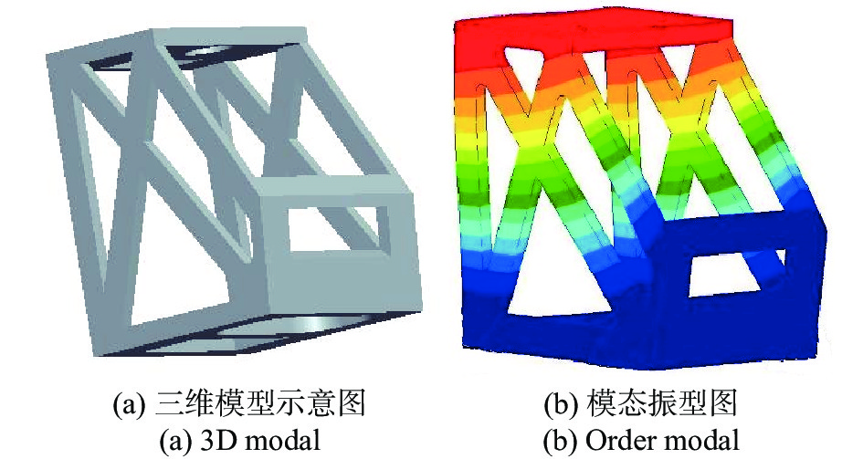
文中可见光相机采用立式安装方式,相比卧式安装具有两个不利因素:(1)相机安装状态与光学装调状态不一致,需克服由重力带来的影响;(2)光学系统中最敏感的反射镜——次镜,位于相机最顶端,其力学条件最恶劣,直接影响相机的成像稳定性。相机主承力结构采用常规的钛合金材料,结合光学系统布局和立式安装特点,采用拓扑优化技术对主承力结构进行了轻量化设计,得到主承力结构基础模型如图2所示。由于立式安装,此时的相机主承力结构一阶频率仅有57.5 Hz。

Figure 2. 3D modal and order modal of main frame before optimization
该结构对相机顶部安装的反射镜的力学环境非常恶劣,为了降低反射镜的力学响应,在主承力结构基础模型上采取加固措施,根据主承力结构顶部传力路径,采取三种措施:(1)增加顶板至底板间的加强筋,并优化加强筋的摆放角度;(2)在次镜周围不遮挡光路的情况下,增加局部加强筋,并优化加强筋的摆放角度;(3)主承力结构镂空部位增加薄壁板提高主承力结构面内的刚度。根据以上措施,经过多次迭代优化,得到主框架最优模型,其一阶频率为168.5 Hz,主承力结构最优模型及一阶模态振型图如图3所示。

Figure 3. 3D modal and order modal of main frame after optimization
-
反射镜组件是三反离轴相机的核心组件之一,反射镜的面形精度直接影响着相机的成像品质[7-8]。为保证反射镜具有良好的环境适应能力,反射镜组件的材料选择、反射镜支撑方式、反射镜组件的稳定性等方面成为反射镜结构设计的重要环节[9-10]。
-
空间遥感相机反射镜材料应具有比刚度大、热变形系数小、导热性能好等特性,常用于可见光反射式的材料有ULE、Zerodur、碳化硅(SiC),三种材料的性能参数如表3所示[11]。综合考虑反射镜口径、热匹配性、成本、加工难度、装调难度等因素,反射镜组件的光学材料选择零膨胀系数的肖特微晶玻璃(ZERODUR),该材料已广泛应用于空间光学遥感器中。
ρ/g·cm–3 E/GPa E/ρ/GN·m·g–1 α/10−6 K–1 λ/W·m–1·K–1 α/λ/10–6 m·W–1 ULE 2.21 67 30.3 0.015 1.3 0.012 Zerodur 2.5 92 36.8 0.09 1.67 0.054 SiC 3.05 390 127.9 2.4 185 0.013 Table 3. Physical properties of typical mirror materials
-
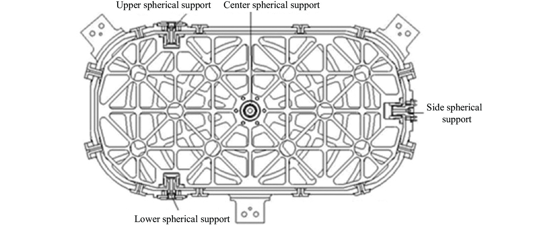
反射镜支撑性能的优劣决定了空间遥感相机的成像质量,目前常用的支撑方式包括周边支撑方式、背部支撑方式和复合支撑方式等[12]。根据反射镜安装位置及通光口径不同,可见光相机反射镜采用两种不同的支撑方式:(1)主镜和三镜选用四点球铰背部支撑方式,通过一个中心球铰、一个侧面球铰和两个侧面偏心球铰配合使用,约束反射镜六个空间自由度,实现静定支撑[13];(2)次镜选用周边支撑方式,通过四周胶粘和轴向压块方式实现次镜固定。
四点球铰背部支撑方式支撑结构示意图如图4所示,周边支撑方式支撑结构示意图如图5所示。

Figure 4. Structure of the subassembly of primary mirror
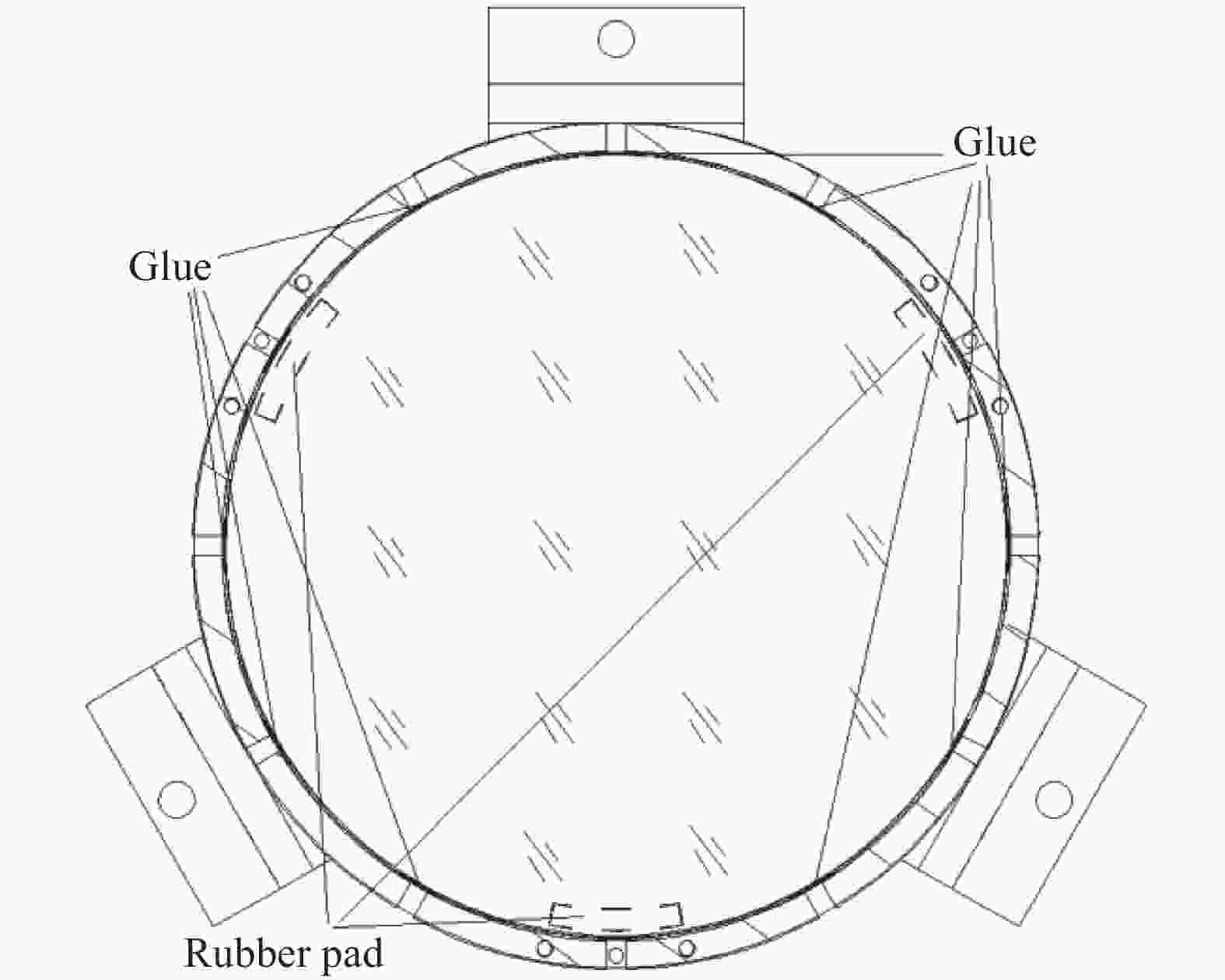
Figure 5. Structure of the subassembly of second mirror
-
在设计过程中重点对反射镜组件频率和重力作用下对面形的影响进行了仿真分析,仿真计算结果满足设计要求,仿真计算情况如下:
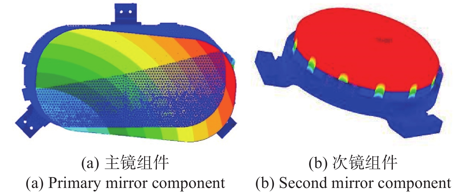
(1)基频分析:通过有限元仿真分析主镜组件的一阶基频大于190 Hz;次镜组件的一阶基频大于330 Hz,模态振形图如图6所示。
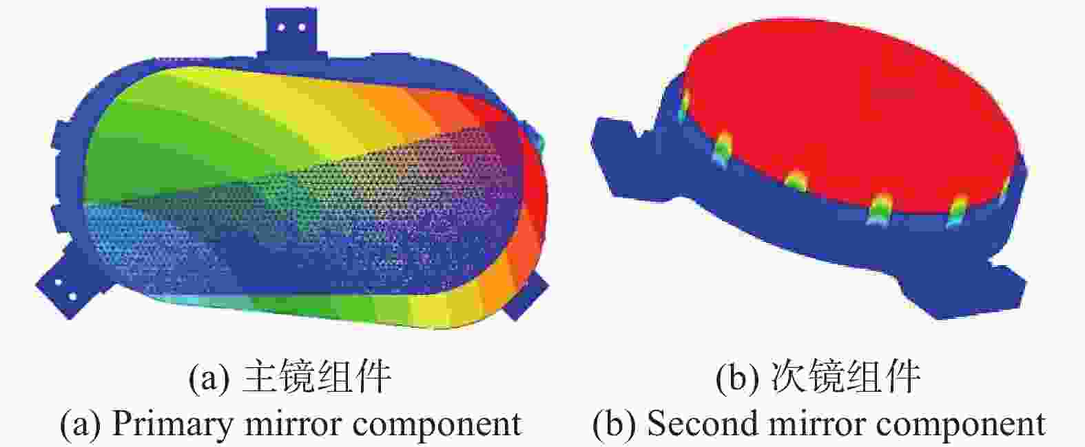
Figure 6. First order modal of mirrors
(2)重力分析:针对X、Y、Z三个方向重力对反射镜面形影响进行了仿真分析,主镜在三个方向重力作用下面形误差RMS值小于3 nm;次镜在三个方向重力作用下面形误差RMS值小于0.5 nm。
(3)温度场分析:在2 ℃温升作用下对反射镜面形影响进行了仿真分析,主镜在温升作用下面形误差RMS值小于0.4 nm;次镜在三个方向重力作用下面形误差RMS值小于0.3 nm。
(4)装配应力分析:在反射镜安装面施加0.01 mm强迫位移作用下对反射镜面型影响进行了仿真分析,主镜在温升作用下面形误差RMS值小于0.3 nm;次镜在三个方向重力作用下面形误差RMS值小于0.9 nm。
通过上述仿真分析结果可知,反射镜两种支撑形式均能够满足光学系统对反射镜结构设计分配的误差要求。
-
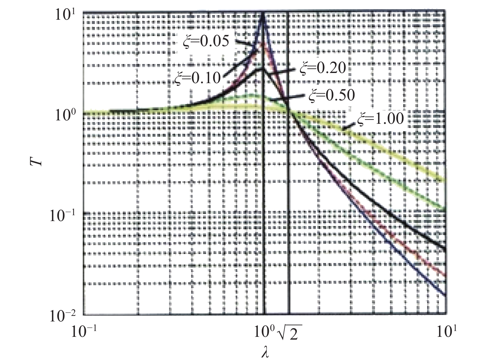
为克服相机立式安装引起的相机顶部尤其是次镜组件在发射过程中力学响应过大的不利因素,除了提高主承力结构和部组件自身的刚度外,还可以增加阻尼减振系统,通过阻尼减振系统特定弹性和阻尼特性以降低从卫星传递到相机上的力学响应。目前常用的减振方式多种多样,如金属橡胶减振器、钢丝绳减振器、丁基橡胶减振器、阻尼桁架等,减振器结构复杂程度也是多样。减振器的主要指标减振效率常用传递率T来描述,传递率定义为传递到需要防振设备上的振动响应(位移响应)幅值与基础的输入激励(位移激励)幅值之比[14]。
图7为单自由度减振系统传递率曲线图[15],其中λ表示频率比,即f/f0。

Figure 7. Single-degree-of-freedom vibration isolation system characteristic curve
从图7可以看出,在传递率T<1时减振系统才会起到隔振效果,相应的,频率比必须满足λ>
$\sqrt 2 $ 的条件,根据该要求对减振器的刚度和阻尼进行优化设计。为减少发射段力学响应的传递率,可见光相机采用阻尼隔振技术,综合考虑阻尼隔振器的结构复杂程度、外形尺寸、衰减效率等因素,可见光相机选用丁基橡胶减振器[16],该减振器是一种结构简单且又高效的隔振装置,丁基橡胶是一种比较适用于压制各种阻尼器、主力垫的粘弹性阻尼材料,该丁基橡胶减振器已广泛应用于空间光学遥感器、卫星姿控元件等领域[17]。减振器的设计结构如图8所示,通过调整丁基橡胶垫的直径、高度参数可以对减振器的刚度和阻尼进行调整。
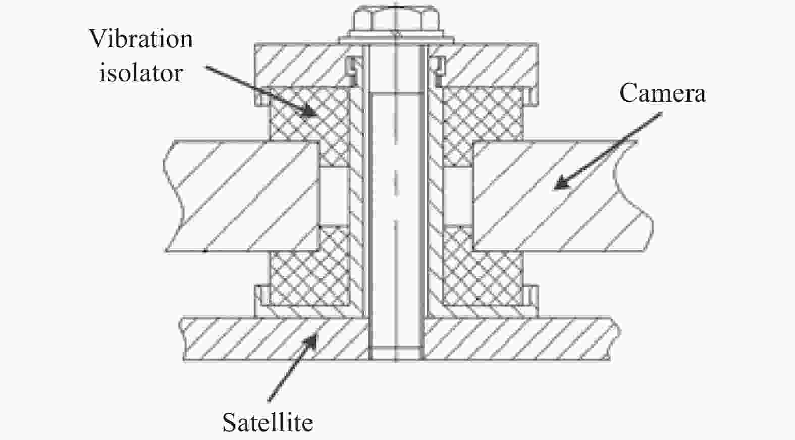
Figure 8. Structure of vibration isolator
由于减振器在λ>
$\sqrt 2 $ 时才能起到减振作用,故通过比对可见光相机在随机振动(20~200 Hz)中有无减振系统来检查减振效果。为确保仿真模型准确性,假设在阻尼胶垫压缩量较小时按线性变化处理,通过项目组进行的大量试验数据分析确定阻尼胶垫的弹性剪切模量为5.7 MPa,阻尼系数为0.25,由此开展仿真分析工作,通过仿真结果可知,减振器的减振效率均大于50%,仿真数据如表4所示。Key points Direction Root mean square acceleration, grms Attenuation ratio Without vibration isolator With vibration isolator Top of main frame X 1.8 0.7 61% Y 1.7 0.6 65% Z 3.7 1.5 59% Bottom of main frame X 2.6 1.0 62% Y 2.2 0.7 68% Z 2.1 1.0 52% Table 4. Results of random vibration
-
为满足可见光相机光机结构设计要求,相机在研制过程中进行了一系列的试验验证、功能性能测试,可见光相机开展了地面力学振动试验和相机立式状态下成像测试。
-
为验证空间遥感相机的刚度及稳定性,在相机完成总装后,进行了力学振动试验,随机振动的均方根加速度为3.0 grms,输入条件如表5所示。
Frequency range/Hz Power spectral density/g2·Hz–1 20-190 0.00114-0.0107 190-500 0.0107 500-750 0.0079 750-2 000 0.0079-0.00042 Table 5. Conditions of random vibration
随机振动试验过程中相机各部位横向衰减率大于50%,纵向衰减率大于45%,相机最大总均方根加速度为3.5 grms,由此验证了相机光机结构设计的强度和刚度满足使用要求;振动试验前后,相机系统级传递函数(MTF)变化小于0.004,外方位元素变化小于10″,由此验证了相机光机结构设计的稳定性满足使用要求。
-
可见光相机采用水平装调,竖直方式使用,使用方向和装调方向不一致,必须考虑重力对相机成像的影响。可见光相机研制完成后进行了立式状态下成像测试。该项测试通过一个45°平面折转镜将水平光线折转入射到立式状态下的相机内部,实现相机成像测试,测试系统如图9所示。
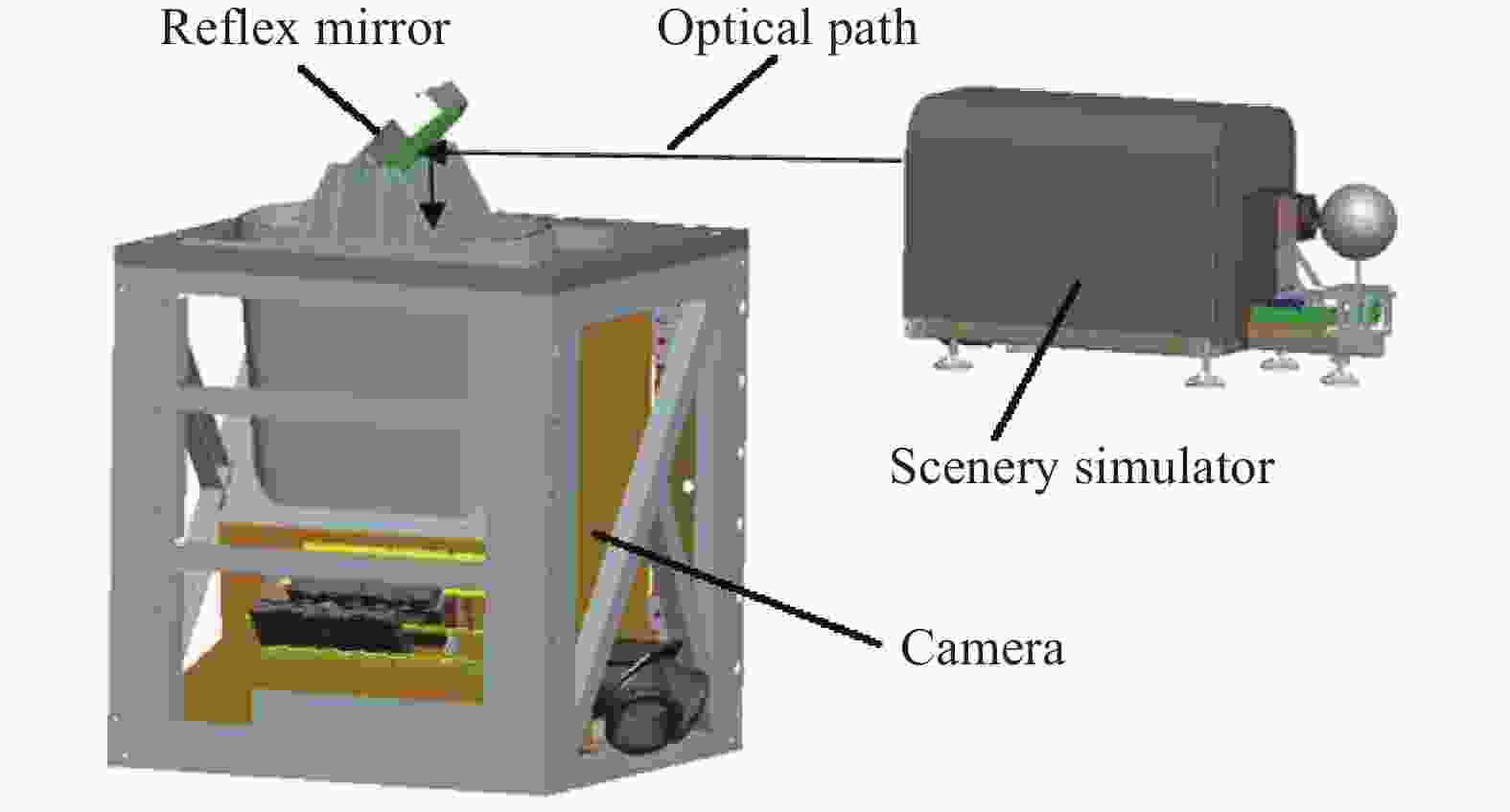
Figure 9. Schematic diagram of test system
通过立式状态下成像测试,相机系统MTF大于0.18 (空间频率71.4 lp/mm)的总体指标要求,验证了可见光相机光机结构设计能够满足相机立式状态成像质量的要求。
-
2019年12月21日,中巴资源一号04A卫星首次进行了在轨成像测试,获得首批影像数据,经过在轨测试与评价,可见光相机影像清晰,层次分明,相机全色谱段在轨动态MTF达到0.135,相机成像质量指标满足用户要求。图10为可见光相机在轨影像图。

Figure 10. Photograph taken by space remote sensing camera in orbit
-
文中介绍了一种箱式主承力结构与被动隔振组合设计,适用于三反离轴相机立式安装形式,详细描述了主承力结构、反射镜组件及隔振系统的光机结构设计方法,通过地面环境试验和在轨验证,验证了光机结构设计的合理性,克服了立式状态下发射段力学环境恶劣的不利因素,能够保证相机在轨稳定成像。
Opto-mechanical structure design of vertical off-axis TMA system camera
doi: 10.3788/IRLA20220303
- Received Date: 2022-05-05
- Rev Recd Date: 2022-09-06
- Available Online: 2022-11-02
- Publish Date: 2022-10-28
-
Key words:
- remote sensing camera /
- opto-mechanical structure design /
- stability /
- off-axis TMA /
- vertical installation
Abstract: China-Brazil Earth Resource Satellite is based on the field of land resources and mainly focuses on high and moderate resolution optical remote sensing. The main payload on the 04A satellite adopts off-axis TMA optical system with large field of view and low distortion. In order to solve the problem of harsh mechanical environment caused by vertical installation of the camera, a solution of box-type main structure and passive vibration isolation is proposed. We start with main frame design, mirror support and vibration isolation measures, the static and dynamic modeling of the off-axis TMA camera is carried out, and the structural form is optimized. Through the optical-mechanical integration analysis, the natural frequency of the structure is improved, the first-order frequency reaches 168 Hz, and the mechanical response of the transmitting section is reduced, the mechanical response of the key components of the camera is attenuated by more than 50%, and the transfer function of the camera system is greater than 0.18. The ground environment test and in-orbit test show that the optical mechanical structure design is reasonable, the mechanical and vibration isolation performance meet the use requirements.


 DownLoad: