


-
激光雷达是一种目前被广泛应用的光学传感器,其可远距离获得目标的二维灰度图像和三维深度图像,为目标的精确识别提供先决条件,因而在无人驾驶[1]、直升机避障、武器制导[2]等领域有着极其广泛的应用前景。早期的激光雷达通过测量光脉冲的飞行时间(Time-of-Flight,ToF)来获得目标的距离信息,常采用纳秒量级的固体激光器作为光源、采用高增益的雪崩二极管(APD)作为探测器,作用距离可达公里量级而测距精度可达厘米量级。随着器件水平的不断发展,激光雷达的器件性能获得不断的提升,出现了一种新的激光雷达体制—时间相关单光子计数(Time-Correlated Single Photon Counting,TCSPC)激光雷达[3]。
TCSPC激光雷达利用时间相关单光子计数技术进行测距,光源一般采用脉冲宽度更窄的皮秒激光器或飞秒激光器,其探测器往往采用单光子雪崩二极管 (Single Photo Avalanche Diode,SPAD)[4-6]。这种探测器具有单光子量级的灵敏度和皮秒量级的时间分辨能力,因而相较于传统激光雷达,在发射功率固定的情况下可实现更远的作用距离和测距精度,可以获得目标精确的三维图像[7]。这种新体制的激光雷达一经提出就引起学者们的重点关注,在激光远距离成像[8-12]、水下深度成像[13]、穿透烟雾成像[14]等各个领域得到广泛的应用,另外强照明下成像[15]和实时三维成像[16]也成为这种体制走向实用所要解决的难题。传统的激光雷达除了测距以外,还可以进行测速,其通常采用多普勒效应获得目标的径向速度[17],探测过程需要本振光和回波在探测器表面进行相干检测,而这种功能难于在TCSPC激光雷达中实现。由于TCSPC激光雷达通过光子计数统计获得信号的波形,因而对于静止的目标往往可以获得精确的距离值。原理上讲,对于运动的目标,该种体制也可以通过对目标的距离进行连续测量,从而获得目标的径向速度。文中针对激光雷达未来测速的应用需求,探索了利用时间相关单光子计数技术实现测速的方法。通过在室内搭建高重频、高精度TCSPC测速激光雷达系统,实验验证了该方法的可行性,同时分析了测速性能的影响因素。
-
首先分析TCSPC方法的测距原理。脉冲激光器发射一束激光脉冲经分束镜后,一束激光照在PIN上输出电脉冲信号,作为计时的起始信号;另一束打在一定距离的目标上,从目标表面返回的散射光子被单光子探测器接收输出电脉冲信号,作为计时停止信号。起始信号和停止信号都输入到时间相关单光子计数器中,由其中的时间幅度转换器TAC记录下光子的飞行时间,以及对应的脉冲周期序列。然后在多通道分析器的不同时间通道进行计数累加,经过大量周期的累加重复后,输出一个与原始信号波形类似的时间相关单光子计数直方图,原理如图1所示。

Figure 1. Schematic diagram of time correlated single photon counting. (a) System diagram; (b) Schematic diagram of the channel analyzer principle
通过记录一段时间内的光子飞行时间及脉冲序列数据,累加获得时间相关单光子计数直方图,通过峰值检测、阈值检测、质心检测等方法可以获得光脉冲的飞行时间
$ {t}_{top} $ ,即可通过飞行时间法进行测距:式中:x为测得的目标距离;c为光速。由于这种方法是通过多次光子计数积累实现精确测距,因而完成一次测距需要一定的积累时间。
对于运动的目标,要求光子计数时间要尽可能短,才能准确获得目标的即时距离。而通过两次以上的即时距离测量,就可以获得目标的即时速度。两次即时距离测速的表达式如公式(2)所示:
式中:
$ {x}_{i-1} $ 、$ {x}_{i} $ 为相邻的两次距离值;∆t为两个测距的时间间隔。如果两次测距的间隔很短,那么测距误差就会引起比较大的测速误差,因而更为合理的方法是采用多次测距结果进行最小二乘法的线性拟合。以脉冲序列个数为依据分组进行多次测距$ {x}_{i} $ ,并采用每组中脉冲序列对应的中心时间点作为测得该距离的时间$ {t}_{i} $ 。采用线性拟合,给出时间-距离曲线关系如公式(3)所示:拟合曲线的斜率v即为该目标的运动速度。
-
为了验证TCSPC技术的测速能力,并且分析测速性能的影响因素,在室内搭建了一套时间相关单光子计数测速系统,具体结构如图2(a)所示。系统中采用中心波长532 nm,重复频率12.5 MHz,脉冲宽度约为5 ps、平均光功率为100 mW的脉冲激光器作为发射照明源。采用盖格型单光子雪崩二极管(SPAD)作为接收探测器,该探测器光子探测效率为49%,

Figure 2. Time correlated single photon counting measuring distance and velocity system. (a) System diagram; (b) Velocity simulator device
时间分辨率为50 ps,暗计数率为50 cps。发射光经反射镜、中性密度衰减片组后,通过万向调节反射镜后出射。利用中性密度衰减片组调节出射光功率,利用万向调节架调整出射光束方向使之与接收光学系统轴线平行以完成系统的调试。
利用如图2(b)所示的速度模拟器装置来模拟运动的目标。该速度模拟器使用交流伺服电机,通过同步齿形带带动大小为5 cm×5 cm的小白板位移,位移速度范围为0.5~5 m/s。实验过程中,速度模拟器距TCSPC测速系统3 m左右,沿测速系统的出射光线方向摆放,目标位移速度设置为2.48 m/s。小白板在运动过程中出射光线均在小白板上。
实验中所用的时间相关单光子计数器最高时间分辨率为16 ps,瞬时饱和计数率100 Mcps,死时间小于10 ns。数据格式有T1,T2,T3三种模式。实验采用的是T3模式,记录总曝光时间内收到的每一个光子的飞行时间及对应的脉冲序列数据,每收到一个光子称为一个事件。调试并打开测速系统后,打开速度模拟器电源,调节中性密度衰减片组,使得单脉冲可收到0.05个光子,设置采集时间为2 s,采集目标静止和匀速运动过程的实验数据。
-
(1)静止测距
从目标静止时的数据中截取
$ 2\times {10}^{5} $ 个脉冲序列中的事件数,累加得到的TCSPC图如图3所示,半峰宽$ \Delta {t}_{s} $ 为5个bin,对应80 ps。这个波形通常被定义为系统的时间响应函数,其半峰宽反映了系统的测时分辨率,其由系统内激光器的脉宽$ {\Delta t}_{laser} $ 、探测器的时间抖动$ {\Delta t}_{sensor} $ 、线路抖动$ {\Delta t}_{electronics} $ 确定,其估计值如公式(4)所示:
Figure 3. TCSPC diagram when the target is stationary
激光器的脉宽、探测器的时间抖动以及线路抖动都是由器件本身决定的,一旦系统确定,该测时分辨率也即确定。这也意味着对于该系统,单个信号光子到达的测时分辨率为80 ps,其对应的测距分辨率为0.012 m。系统是通过积累很多个光子形成TCSPC波形,从波形的特征点来判断光脉冲的飞行时间,从而折算距离,因而测距精度往往取决于单光子测时精度和积累的光子数。
(2)运动测速
从目标运动时的数据以
$ 2\times {10}^{4} $ 个脉冲序列对应的光子数为一组统计得到测距结果与对应时间,做出如图4所示的t-x图,截取0.4~0.6 s的匀速部分进行数据分析。在截取T=0.2 s内的匀速部分对应的数据中,以不同数量的光子数累计进行单次测距测时,累加的部分TCSPC图如图5所示,对应的单次测量积累时间为$ \Delta t $ ,以不同数量的光子数累计进行测距测时的次数如公式(5)所示:
Figure 4. The t-x diagram of the uniform motion process of the target
单次测量的光子数越多,
$ \Delta t $ 越多。图5(a)中累计到的光子数大约几十个,并没有形成完整的测距峰,只是峰位处出现密集的光子计数。这种情况下难以准确提取信号波形的测时特征,产生较大的测距误差,甚至是错误。随着积累时间增加,图5(b)中出现明显的测距峰,该峰的形状已近趋近于目标静止时的测距峰,测距精度达到最佳。随着积累时间的进一步增加,图5(c)中的测距峰出现展宽现象,这主要是由于在积累时间内,目标移动的距离已经可以和测距峰的宽度相比拟,对测距峰产生展宽效应,此时测距精度会受到一定程度的影响。如果积累时间更进一步增加,图5(d)中的测距峰已经被展宽的非常严重,此时去寻找测时特征已经非常困难,测距精度严重恶化,甚至出现测距错误。按照前述测速原理,需要连续完成n次单次测距,然后根据多个单次测距的结果来进行数据拟合,这里采用最小二乘法对图5中的各数据进行线性拟合[18],可得公式(6):
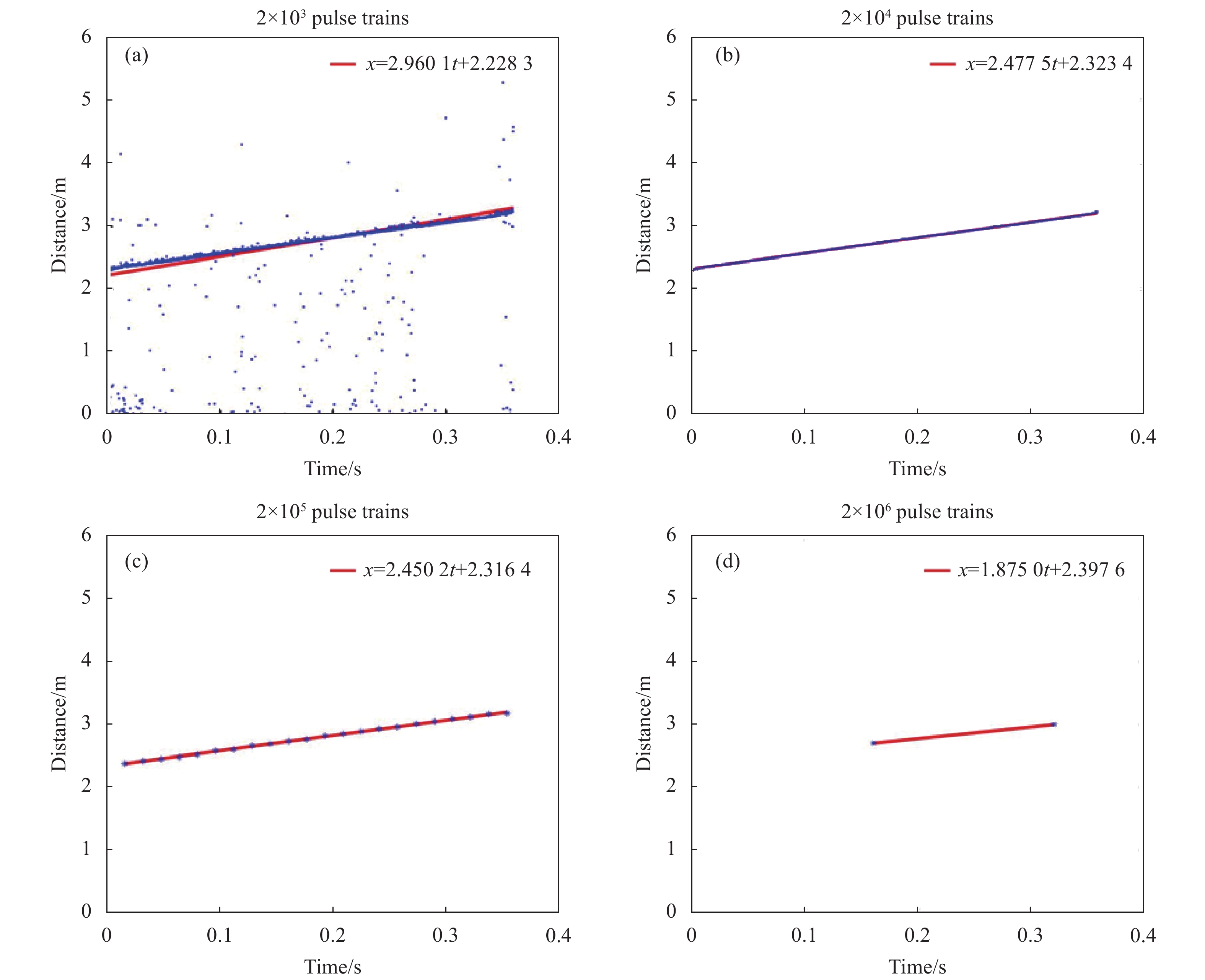
画出部分t-x图如图6所示,图6(a)中显示由于单次测距误差较大,因而测距点在拟合直线两侧形成比较大的起伏,另外在远离拟合直线的地方仍存在大量的错误点数据,这对直线的拟合精度都将产生明显的影响。图6(b)由于单次测距误差较小,因而测距点在拟合直线两侧形成比较小的起伏,直线的拟合精度较高。图6(c)中测距点在拟合直线两侧形成的起伏有所增加,同时拟合点的数量明显减少,这样也同样会降低拟合精度。图6(d)中的测距点误差较大,而测距点的数量最少,因而拟合直线的精度产生很大的误差。

Figure 5. The TCSPC graphs obtained by accumulating the number of photons with different numbers, from (a) to (d) are
$ 2\times {10}^{3} $ ,$ 2\times {10}^{4} $ ,$ 2\times {10}^{5} $ , and$ 2\times {10}^{6} $ pulses the number of photons accumulated within the sequence number对于TCSPC测时模块,其最小测时间隔为16 ps,此时可以认为
$ {t}_{i} $ 的误差远小于距离$ {x}_{i} $ 的误差,这种情况下,根据最小二乘法的拟合误差分析[19],可以给出测速误差表达如公式(7)所示:式中:
$ {\sigma _x} $ 为单次测距的标准差;T为测速时长;n为测量次数。由上式可知,速度的标准差与单次测距误差、测量次数、测量时长均有关系。在测速时长不变的情况下,单次测距误差对测速的影响比较大,测量次数同样会有一定的影响。而单次测距误差以及测量次数均与单次测距光子计数直接相关,如表1所示。从表中可以看出,单次测距的光子计数数量太小或太大均会产生较大的影响,光子计数数量较小时,单次测距信号的信噪比太小,测距误差太大,即使测量次数很多,也无法补偿最终的测速精度。光子计数数量较大时,单次测距的积分时间太长,单次测距误差受目标运动影响较大,同时测量次数也大幅降低,因而最终的测速误差也会很大,因而,适当地选取光子计数数量才能达到最佳的测速性能。在实验条件下,单次测距选取 1000~5000个光子数对应的时延为1.6~8 ms,对应目标运动的距离为0.002~0.01 m,在单次测距时间内目标的运动距离在测距分辨率以内。换言之,每次测距时可认为目标是近似不动的,此近似下光子数积累越多,测速精度越高。从表中可以看出TCSPC测速单次测量在选择5000个光子数时,测速相对误差达到了最小0.04%。故在文中系统及测量条件下,单次测距选择1000~5000个光子数时对应的测速误差最小。
Figure 6. The t-x diagrams formed by measuring distance with different photon numbers, from (a) to (d) are
$ 2\times {10}^{3} $ ,$ 2\times {10}^{4} $ ,$ 2\times {10}^{5} $ and$ 2\times {10}^{6} $ pulses the number of photons accumulated within the sequence numberNumber of pulse sequences for
single measurement/piecesAverage number of photons in a
single measurement/piecesMeasured value/m·s−1 Absolute error/m·s−1 Relative error $ 1\times {10}^{3} $ $ 5\times {10}^{1} $ 3.453 0.973 39.23% $ 2\times {10}^{3} $ $ 1\times {10}^{2} $ 2.96 0.48 19.35% $ 1\times {10}^{4} $ $ 5\times {10}^{2} $ 2.488 0.008 0.32% $ 2\times {10}^{4} $ $ 1\times {10}^{3} $ 2.478 0.002 0.08% $ 1\times {10}^{5} $ $5\times {10}^{3}$ 2.481 0.001 0.04% $ 2\times {10}^{5} $ $ 1\times {10}^{4} $ 2.467 0.013 0.52% $ 1\times {10}^{6} $ $ 5\times {10}^{4} $ 2.449 0.031 1.25% $ 2\times {10}^{6} $ $ 1\times {10}^{5} $ 1.875 0.605 24.40% Table 1. Accumulation of different numbers of photons and corresponding velocity measurement value, absolute deviation and relative deviation of velocity measurement
目前激光多普勒测速方法已经比较成熟,特别是自混合测速模式,结构简单,且对激光器的相干性要求也更低。但目前多普勒测速方法难以使用高灵敏的单光子探测器实现更远的作用距离。文中探索使用单光子探测器,在测距的同时获得速度信息。未来有望采用单光子探测器阵列,在远距离下获得目标的距离像和速度像,提高目标识别率。
另外,阳光背景会严重影响TCSPC系统的信噪比,甚至导致单光子探测器饱和而无法工作。在实际应用当中,首先可以考虑采用短波红外如1550 nm的激光器作为照明光源,该波段对应的阳光背景相对较小;其次可采用窄带滤波片,目前商用的滤波片带宽已低至纳米量级以下,可有效滤除背景光;最后,时间选通技术也是降低背景光的有效手段之一,目前单光子探测器的选通门宽可以低至10 ns以下,可大幅削减背景光。上述方法均已在TCSPC远距离测距系统中得到广泛的应用[9,11],使得系统在白天日照条件下可以正常工作。
-
为满足TCSPC激光雷达在未来的测速应用需求,文中搭建了一套高重频、高精度TCSPC测速系统,验证了TCSPC技术精确测速的可行性,研究表明在一定的测速时长下,测速误差与单次测距误差、测量次数均有关系。单次测距误差以及测量次数均与单次测距光子计数直接相关,单次测距的光子计数数量太小或太大均会产生较大的影响,因而,适当地选取光子计数数量才能达到最佳的测速性能。在实验条件下,单次测距光子计数在1000~5000个时测速误差达到最小。该方法可以在微弱的光照环境下实现对运动目标的速度测量。未来有望代替多普勒测速方法,实现对远距离高速运动目标的测速,还可以完成目标速度图像的获取,辅助目标的识别。
Research on velocity measurement based on time-correlated single photon counting
doi: 10.3788/IRLA20220565
- Received Date: 2022-08-11
- Rev Recd Date: 2022-08-31
- Available Online: 2022-11-02
- Publish Date: 2022-10-28
-
Key words:
- lidar /
- TCSPC technology /
- velocity measurement
Abstract: The traditional lidar usually uses Doppler effect to obtain the radial velocity of the target, but it is difficult to achieve this function when the echo signal is as low as single photon level. In this paper, we explore a method of velocity measurement using time-correlated single photon counting (TCSPC) technology. We have built a high repetition rate and high precision TCSPC velocity measurement system and carried out experimental research. The results show that the velocity measurement error is directly related to the photon count for single ranging under a certain velocity measurement duration, and the velocity measurement error is optimal when the photon count for single ranging is 1000-5000 under the experimental conditions in this paper. This method is expected to replace the Doppler velocity measurement method in the future and realize the velocity measurement of long-distance and high-speed moving targets.


 DownLoad: