Volume 52 Issue 5
May  2023
Turn off MathJax
Article Contents

Yang Jing, Han Yuli, Xue Xianghui, Chen Tingdi, Zhao Yiming, Sun Dongsong. Design and analysis of laser wind velocimetry for stratospheric airships[J]. Infrared and Laser Engineering, 2023, 52(5): 20220642. doi: 10.3788/IRLA20220642
Citation: Yang Jing, Han Yuli, Xue Xianghui, Chen Tingdi, Zhao Yiming, Sun Dongsong. Design and analysis of laser wind velocimetry for stratospheric airships[J]. Infrared and Laser Engineering, 2023, 52(5): 20220642. doi: 10.3788/IRLA20220642

Design and analysis of laser wind velocimetry for stratospheric airships

doi: 10.3788/IRLA20220642
Funds:  National Natural Science Foundation of China (41774193)
  • Received Date: 2022-09-08
  • Rev Recd Date: 2022-11-01
  • Publish Date: 2023-05-25
  •   Objective   The wind field is one of the most critical impacts in the specifying stratospheric airships and plays a practical fundamental role in flying safety. The airship has attracted increasing interest and made it a tremendous potential of long-time fix-station residence missions at nearly the altitude range of the stratosphere bottom 18-22 km. Its integrating superiority, such as broad covering, and large load capacity, has been proven as effective and powerful operational buoyant platform to contribute to more accurate remote sensing of environment monitoring, resource exploration, and meteorological research. Due to the Earth’s periodic rotation, there is an extremely strong west wind region in low stratosphere while the wind speed changes along with the season, the latitude and longitude, and the height. The key challenges for applying a wind measurement system in the low stratosphere (20 km), which has significant differences from the terrestrial environment, are the low densities and the low pressures at the working height of the high-altitude airship. This represents a precise measurement that is essential to detect the atmosphere parameters of wind. For this purpose, a laser wind velocimetry system for the stratospheric airship is proposed.  Methods   A compact laser anemometer is designed using dual-channel Fabry-Perot etalon to analyze Doppler shift due to high-speed thermal motion at molecular scale. Atmospheric molecular scattering mainly consists of a strong Rayleigh-Brillouin spectrum (Fig.1). The system generally consists of four major subsystems, which are the 532 nm fiber pulsed laser transmitter subsystem, the telescope subsystem, a photocounting detection (PD) subsystem and computer controlling subsystem (Fig.5). The liquid crystal phase variable retarder (LCVR) is chosen to be a controller between two lines-of sight (LOS) for the successive horizontal speed estimates with a novel non-mechanical structure in the detection. The radial wind velocity can be uniquely determined by measuring the ratio of the two channel edge signals of Fabry-Perot etalon.  Results and Discussions   In the beginning of the experiment, it is an indispensable step of the laser anemometer system design and study that the theoretical parameters must be preliminarily confirmed (Tab.1). According to the thin air characteristics at the airship flying altitude of 20 km, the improvement of signal noise ratio (SNR) and velocity errors are simulated. Assuming the Doppler shift is 0, the FWHM of the outgoing laser spectrum is 400 MHz, and the low stratosphere temperature is set at 216.5 K. The radial wind measurement error as a function of the free spectral range (FSR) of the Fabry-Perot etalon is given (Fig.8). As shown, to fully analyze the Rayleigh-Brillouin spectrum, the free spectral range (FSR) of the Fabry-Perot etalon is chosen to be 6.5 GHz with the minimum error occurrence in the system (Fig.8). At the same time, the spectral spacing of the Fabry-Perot etalon is required to be 3.25 GHz due to the same velocity sensitivity for both molecular and aerosol backscattering (Fig.9). The SNR of more than 180 is obtained due to the fact that the spectral radiance value of the solar background is still very small in the daytime and nighttime (Fig.10). The velocity error is less than 1 m/s up to 500 m distance with wind velocity of 100 m/s (Fig.11).  Conclusions  Using dual-channel Fabry-Perot etalon with fixed cavity length for frequency discriminator and a 532 nm fiber pulsed laser, the structural design of the laser wind velocimetry was completed. The system referred to optical path of coherent wind measurement lidar and adopted monostatic telescope, which had no blind area and smaller receiving field of view, thus improving performance of all-sky detection. The polarization property of liquid crystal variable retarder was used to control direction of the detected optical path. The system performance of wind field detection was also analyzed. The average power of 500 mW laser, the integration time of 10 s, and the range resolution of 100 m during simulation are selected. The analysis results illustrate the maximum wind speed error of 1 m/s and wind direction error of 5° under the wind speed condition of larger than 10 m/s, respectively. The theoretical results highly meet wind detection requirements in navigation environment of stratospheric airships.
  • [1] Mueller J B, Zhao Y J, Garrard W L. Optimal ascent trajectories for stratospheric airships using wind energy [J]. Journal of Guidance, Control, and Dynamics, 2009, 32(4): 1232-1245. doi:  10.2514/1.41270
    [2] Shen S P, Liu L, Huang B M, et al. Wind speed estimation and station-keeping control for stratospheric airships with extended kalman filter [J]. Lect Notes Electr En, 2015, 337: 145-157. doi:  10.1007/978-3-662-46463-2_17
    [3] Zhang Lanchuang, Meng Junhui, Lü Mingyun. Stratospheric airship airborne velocity measurement [J]. Science & Technology Review, 2017, 35(2): 80-86. (in Chinese) doi:  10.3981/j.issn.1000-7857.2017.02.011
    [4] Gentry B M, Chen H L. Tropospheric wind measurements obtained with the Goddard Lidar Observatory for Winds (GLOW): Validation and performance [C]//Proceedings of SPIE, 2001, 4484: 74-81.
    [5] Bruneau D, Pelon J. A new lidar design for operational atmospheric wind and cloud/aerosol survey from space [J]. Atmospheric Measurement Techniques, 2021, 14(6): 4375-4402. doi:  10.5194/amt-14-4375-2021
    [6] Dou X K, Han Y L, Sun D S, et al. Mobile Rayleigh Doppler lidar for wind and temperature measurements in the stratosphere and lower mesosphere [J]. Optics Express, 2014, 22(5): A1203-1221. doi:  10.1364/OE.22.0A1203
    [7] Chu Jiaqi, Han Yuli, Sun Dongsong, et al. Small scale optical receiver of spaceborne Doppler wind lidar [J]. Infrared and Laser Engineering, 2022, 51(9): 20210831. (in Chinese) doi:  10.3788/IRLA20210831
    [8] Yan Zhaoai, Hu Xiong, Guo Wenjie, et al. Near space doppler lidar tech-niques and applications [J]. Infrared and Laser Engineering, 2021, 50(3): 20210100. (in Chinese) doi:  10.3788/IRLA20210100
    [9] Souprayen C, Garnier A, Hertzog A. Rayleigh-mie doppler wind lidar for atmospheric measurements. II. mie scattering effect, theory, and calibration [J]. Applied Optics, 1999, 38(12): 2422-2431. doi:  10.1364/Ao.38.002422
    [10] Han Fei, Liu Hengjia, Sun Dongsong, et al. Design and analysis of uitra-narrow filter of Rayleigh lidar [J]. Infrared and Laser Engineering, 2020, 49(2): 0205003. (in Chinese) doi:  10.3788/IRLA202049.0205003
    [11] Liang K, Ma Y, Cheng F, et al. Accuracy analysis on Rayleigh lidar measurements of atmospheric temperature based on spectroscopy [J]. Chinese Optics Letters, 2009, 7(3): 173-175. doi:  10.3788/COL20090703.0173
    [12] Boley C D, Desai R C, Tenti G. Kinetic models and Brillouin scattering in a molecular gas [J]. Canadian Journal of Physics, 1972, 50(18): 2158-2173. doi:  10.1139/p72-286
    [13] Tenti G, Boley C D, Desai R C. On the kinetic model description of Rayleigh-brillouin scattering from molecular gases [J]. Canadian Journal of Physics, 1974, 52(4): 285-290. doi:  10.1139/p74-041
    [14] Witschas B. Analytical model for rayleigh-brillouin line shapes in air [J]. Applied Optics, 2011, 50(29): 267-270. doi:  10.1364/Ao.50.000267
    [15] Korb C L, Gentry B M, Li S X, et al. Theory of the double-edge technique for Doppler lidar wind measurement [J]. Applied Optics, 1998, 37(15): 3097-3104. doi:  10.1364/ao.37.003097
    [16] Korb C L, Gentry B M, Weng C Y. Edge technique: theory and application to the lidar measurement of atmospheric wind [J]. Applied Optics, 1992, 31(21): 4202-4013. doi:  10.1364/AO.31.004202
    [17] Zhang Nannan, Han Yuli, Chen Tingdi, et al. Design of direct detection doppler lidar with coherent light path [J]. Chinese Journal of Lasers, 2017, 44(10): 1010005. (in Chinese) doi:  10.3788/CJL201744.1010005
    [18] Zheng J, Sun D S, Chen T D, et al. Wind profiling from high troposphere to low stratosphere using a scanning Rayleigh Doppler lidar [J]. Optical Review, 2018, 25(6): 720-728. doi:  10.1007/s10043-018-0471-y
    [19] Henderson S W, Gatt P, Rees D, et al. Wind Lidar: Part 7[M]//Laser Remote Sensing. Boca Raton: CRC Press, 2005.
  • 加载中
通讯作者: 陈斌, bchen63@163.com
  • 1. 

    沈阳化工大学材料科学与工程学院 沈阳 110142

  1. 本站搜索
  2. 百度学术搜索
  3. 万方数据库搜索
  4. CNKI搜索

Figures(11)  / Tables(1)

Article Metrics

Article views(165) PDF downloads(31) Cited by()

Related
Proportional views

Design and analysis of laser wind velocimetry for stratospheric airships

doi: 10.3788/IRLA20220642
  • 1. School of Earth and Space Sciences, University of Science and Technology of China, Hefei 230026, China
  • 2. Key Laboratory of Geospace Environment, Chinese Academy of Sciences, Hefei 230026, China
  • 3. Anhui Mengcheng Geophysics National Observation and Research Station, Bozhou 233527, China
  • 4. Beijing Research Institute of Telemetry, Beijing 100076, China
Fund Project:  National Natural Science Foundation of China (41774193)

Abstract:   Objective   The wind field is one of the most critical impacts in the specifying stratospheric airships and plays a practical fundamental role in flying safety. The airship has attracted increasing interest and made it a tremendous potential of long-time fix-station residence missions at nearly the altitude range of the stratosphere bottom 18-22 km. Its integrating superiority, such as broad covering, and large load capacity, has been proven as effective and powerful operational buoyant platform to contribute to more accurate remote sensing of environment monitoring, resource exploration, and meteorological research. Due to the Earth’s periodic rotation, there is an extremely strong west wind region in low stratosphere while the wind speed changes along with the season, the latitude and longitude, and the height. The key challenges for applying a wind measurement system in the low stratosphere (20 km), which has significant differences from the terrestrial environment, are the low densities and the low pressures at the working height of the high-altitude airship. This represents a precise measurement that is essential to detect the atmosphere parameters of wind. For this purpose, a laser wind velocimetry system for the stratospheric airship is proposed.  Methods   A compact laser anemometer is designed using dual-channel Fabry-Perot etalon to analyze Doppler shift due to high-speed thermal motion at molecular scale. Atmospheric molecular scattering mainly consists of a strong Rayleigh-Brillouin spectrum (Fig.1). The system generally consists of four major subsystems, which are the 532 nm fiber pulsed laser transmitter subsystem, the telescope subsystem, a photocounting detection (PD) subsystem and computer controlling subsystem (Fig.5). The liquid crystal phase variable retarder (LCVR) is chosen to be a controller between two lines-of sight (LOS) for the successive horizontal speed estimates with a novel non-mechanical structure in the detection. The radial wind velocity can be uniquely determined by measuring the ratio of the two channel edge signals of Fabry-Perot etalon.  Results and Discussions   In the beginning of the experiment, it is an indispensable step of the laser anemometer system design and study that the theoretical parameters must be preliminarily confirmed (Tab.1). According to the thin air characteristics at the airship flying altitude of 20 km, the improvement of signal noise ratio (SNR) and velocity errors are simulated. Assuming the Doppler shift is 0, the FWHM of the outgoing laser spectrum is 400 MHz, and the low stratosphere temperature is set at 216.5 K. The radial wind measurement error as a function of the free spectral range (FSR) of the Fabry-Perot etalon is given (Fig.8). As shown, to fully analyze the Rayleigh-Brillouin spectrum, the free spectral range (FSR) of the Fabry-Perot etalon is chosen to be 6.5 GHz with the minimum error occurrence in the system (Fig.8). At the same time, the spectral spacing of the Fabry-Perot etalon is required to be 3.25 GHz due to the same velocity sensitivity for both molecular and aerosol backscattering (Fig.9). The SNR of more than 180 is obtained due to the fact that the spectral radiance value of the solar background is still very small in the daytime and nighttime (Fig.10). The velocity error is less than 1 m/s up to 500 m distance with wind velocity of 100 m/s (Fig.11).  Conclusions  Using dual-channel Fabry-Perot etalon with fixed cavity length for frequency discriminator and a 532 nm fiber pulsed laser, the structural design of the laser wind velocimetry was completed. The system referred to optical path of coherent wind measurement lidar and adopted monostatic telescope, which had no blind area and smaller receiving field of view, thus improving performance of all-sky detection. The polarization property of liquid crystal variable retarder was used to control direction of the detected optical path. The system performance of wind field detection was also analyzed. The average power of 500 mW laser, the integration time of 10 s, and the range resolution of 100 m during simulation are selected. The analysis results illustrate the maximum wind speed error of 1 m/s and wind direction error of 5° under the wind speed condition of larger than 10 m/s, respectively. The theoretical results highly meet wind detection requirements in navigation environment of stratospheric airships.

    • 平流层飞艇是一种重要的任务载荷浮空平台,工作高度通常为低平流层(18~22 km),具有长时间高空驻留和低成本运行的优势,在通讯、侦察、大气探测等军用和民用领域都有着广泛的应用场景和巨大的潜力。与地球低轨道卫星相比较,飞艇拥有更大的视场范围,不受轨道高度限制,有利于高精度观测,同时在应急救援、通信和遥感等任务中飞艇比传统的飞行器能提供更强的优势性能[1]

      低平流层区域的空气密度较为稀薄,作为比空气更轻的飞行器,平流层飞艇结构疏松,体型庞大。考虑到地球的转动,当风速随着高度、经度、纬度和季节发生变化时,平流层中纬度地区将会产生强烈的西风,驻留区域的大气风场对飞艇的姿态控制起着不容忽视的关键作用,风场测量对平流层飞艇航行保障是一个非常重要的安全问题[2]。由于平流层飞艇长时间驻留在20 km高度的指定空间区域,通常飞行速度缓慢,传统机载风速计响应时间长,易受环境因素干扰,测量重复性差,对小幅度的风速变化往往不能够精确测量,使得驻空区域高度的风场测量误差较大,无法满足飞艇理论分析和实际控制的需求[3]

      激光遥感技术具有高时空分辨率、探测范围广、快速地精确测量大气风场信息的能力,广泛应用于地基、机载和星载的大气风场探测任务中。在2005年,Brunce Gentry等人在美国加利福尼亚州研发了分子直接探测多普勒激光雷达,搭载在飞机上进行机载实验,飞行高度为18 km,激光器运行波长是355 nm,在晴朗天气条件可实现地面至18 km高度的风速廓线探测[4]。2018年8月,欧洲航天局(ESA)顺利发射Aeolus卫星,搭载了基于紫外355 nm工作波长的测风激光雷达(ALADIN),垂直分辨率为250 m~2 km,可探测地球表面到30 km之间的风廓线信息[5]。2014年,中国科学技术大学成功研制了临近空间15~60 km高度的测风激光雷达[6-8]。尽管目前高空多普勒测风系统已经有很多应用,但针对20 km高度处的平流层飞艇类的小型、在线风场的探测设备,尚无进行激光风速测量的相关研究报道。

      针对平流层飞艇的航行保障需求,文中设计了一种基于相干光路的艇载直接探测多普勒激光风速仪,利用液晶相位延迟器(LCVR)的偏振特性,突破了传统的直接测风系统单一方向探测的局限性,采用收发合置的望远镜光路设计,使得系统的接收视场角较小。同时结合相干和直接测风激光遥感系统的各自优势,激光风速仪具有无探测盲区、光路稳定性好、探测效率高等优点。考虑到将来平流层飞艇搭载的任务需求,对系统风场探测性能进行了仿真分析。

    • 激光脉冲在干净的低平流层大气中传输,将会受到大气分子散射的影响。分子直径数量级通常为10−10,远比激光波长小得多,在20 km高度处两者相互作用会产生分子散射,即瑞利散射、拉曼散射和布里渊散射[9-10]。目前瑞利-布里渊散射谱较为广泛地被运用在空间物理和大气遥感探测中,如大气中空气温度分布和风速的测量等[11]

      为了获得对瑞利-布里渊散射的理论描述,通过求解线性化玻耳兹曼方程的近似解引入了Tenti S6模型,该模型是当前公认的描述瑞利-布里渊散射最为准确的理论散射数学模型,它是温度和压强的函数,再利用美国1976标准大气模型可计算得到探测高度处的气体分子后向散射分布谱[12-13]

      两个无量纲参数xy可被用来表示瑞利-布里渊散射谱线型,x描述经过归一化后的光波频移量,y描述光波与介质分子之间的经过归一化后的碰撞频率,瑞利-布里渊散射谱线型的具体表达式为[14]

      式中: ω为散射光波与入射光波之间的角频移;k为波矢量振幅;$ {\kappa _B} $为玻耳兹曼常数;n为气体数量密度;T为大气温度;υ0为分子的热运动速度;η′为剪切粘度;$ A $$ {\sigma _R} $$ {\sigma _B} $$ {x_B} $分别为动力学区域内的整体强度、瑞利散射标准差、布里渊散射标准差和偏移量,它们都与无量纲参数y取值相关。

      瑞利-布里渊散射谱宽与大气温度有关,通过美国1976标准模式得到平流层20 km处的大气温度T为216.5 K。当大气散射受到不同的风速影响时,瑞利-布里渊散射谱将发生明显的偏移,如图1所示。相比出射激光线宽400 MHz,瑞利-布里渊散射谱宽通常较宽,约为2 GHz,当使用激光器工作波长为532 nm,大气风速为100 m/s,大气散射产生的多普勒频移$ \Delta {\nu _{{\text{DOP}}}} $可达到375 MHz左右,该宽谱信号频移可通过双通道法布里-珀罗(F-P)标准具测量获得。

      Figure 1.  Double edge measurement principle

    • 系统接收相应的大气后向散射信号,利用F-P标准具双边缘技术对被频移的散射光进行鉴频,鉴频部分采用中心频率分别为${\nu _1}$${\nu _2}$的F-P标准具1和F-P标准具2作为双边缘滤波器,利用双边缘通道信号的比值可反演得到对应的多普勒频率[15]

      F-P标准具的构成是两块平行的平板玻璃,采用固定式标准具设计,即两玻璃平行板相对位置固定,板的内表面镀有反射膜,光在两个平板之间产生多光束干涉,标准具的透射率曲线由调节激光器的频率扫描得到,其透过率曲线具有陡峭的边缘特征。双边缘测量原理如图1所示,利用频谱分布相同而中心频率分开的两个F-P标准具1和2作为边缘滤波器,两个标准具的透射率位于瑞利-布里渊散射谱的两翼。透射光会根据入射光频率变化而产生明显区别的强度变化,大气后向散射信号被光电探测器接收,从而得到不同距离处的多普勒频率,即后向散射光频率$ v $与激光发射频率${\nu _{{\text{Laser}}}}$的差值。

      根据不同频率的光通过F-P标准具的透射率不同,通过调节激光器的频率扫描得到F-P标准具的透射率曲线。F-P标准具透射率随入射光频率的变化用方程表示为[16-17]

      式中:$F$为标准具的有效精细度;FSR为标准具的自由谱间距;$ {\delta _\delta } $为入射光束发散角;$ {T_P} $是标准具的峰值透过率,与标准具平板的吸收损耗率和平板内表面膜层反射率有关。

      F-P标准具的透过率曲线一般无法直接被测量,根据双边缘理论可知,大气后向散射信号的透过率函数是有一定发散射角的出射激光入射至F-P标准具的透过率曲线和瑞利-布里渊散射Tenti S6模型的卷积,其表达式为[17]

      定义距离z处的多普勒测量响应函数为:

      式中:$ {T_1}(v,z) $${T_2}(v,z)$分别为通过F-P标准具1和2的透过率曲线。

      定义R的频率相对灵敏度函数为:

      那么,多普勒频移的计算公式为:

      式中:$ R(\Delta {\nu _{{\text{DOP}}}},z) $$ R(0,z) $分别为接收的信号光和发射激光频率对应的响应函数值。

      发射激光频率对应的零频多普勒响应函数$ R(0,z) $可通过公式(4)得到,当系统开始风速测量的时候,双通道的光电探测器接收信号光子,从而可以得到对应的信号光响应函数$ R(\Delta {\nu _{{\text{DOP}}}},z) $。大气后向散射信号光的多普勒频移可由公式(6)计算得到,由此可得到相对应的大气风速值。

    • 由于光的多普勒效应,不同距离的大气分子散射回波信号频率发生多普勒频移,采用双通道光学F-P标准具分析回波信号相对激光频率的变化,由此反演出空间不同距离处的径向风速分布,通过不同角度的探测和矢量合成得到平流层飞艇的水平风场分布。激光风速仪的径向风速计算公式为:

      式中:$\lambda $为激光器的工作波长。

      平流层飞艇激光风速仪的发射望远镜在20 km高度处指向水平测量方向,出射激光方向与水平面的法线方向成90°。文中系统通过光路转换设计,先后探测两个相互正交方向的径向风。如图2所示,以正东方向为X轴正方向,正北方向为Y轴正方向,Z轴垂直向上建立直角坐标系,以0°风向对应正北Y轴方向。图中θ是系统与Z轴方向的角度,VxVy分别为风矢量V沿X轴、Y轴的径向风分量Vr1Vr2Vz为风矢量V沿Z轴的垂直分量,Vh为水平风速,Φh为水平风向。

      Figure 2.  Schematic of horizontal wind measurement

      实际测量中,风场风速大小一定,可表示为:

      由于文中系统出射激光为水平方向,在20 km处仅探测水平风场,当只考虑水平风场时,利用两个相互正交方向的径向风先后测量水平风场的x分量Vxy分量Vy,再根据图2中几何关系矢量合成实际的水平风场分布,则水平风速大小和方向可以表示为[18]

      通常在三维风场探测中,在激光发射水平方位角为均匀分布时,即相邻发射激光束的水平方位夹角相等,根据误差理论和公式(8)的推导,可得到风矢量沿X轴、Y轴、Z轴三方向的风场探测误差分别为[19]

      式中:$\delta {V_r}$为系统的径向风速测量误差;N为径向风速的测量数。

      由公式(10)可以进一步推导出大气三维矢量风速和风向探测误差分别为:

      一般地平流层18~20 km高度附近是准零风层,上下层纬向风风向相反,气象场相对稳定。如果垂直风速非常小,其垂直风速远小于水平风速,笔者假定Vz=0 m/s,激光风速仪在20 km高度处指向水平测量方向,则大气风速探测误差和风向探测误差分别可化简为:

      考虑系统与Z轴垂直方向角度为90°,取不同的径向风速测量数N,大气风速探测误差随径向风速误差的变化如图3所示。从图中可以看出径向风速测量数越多,对应的风速探测误差越小,由于文中系统先后探测两个正交方向的风速,所以径向风速测量数取为2,当θ为90°时,根据风速探测误差公式(12),可得到大气风速探测误差就是径向风速误差值,两者的误差变化趋势一致。

      Figure 3.  Wind velocity detection error versus radial wind velocity error

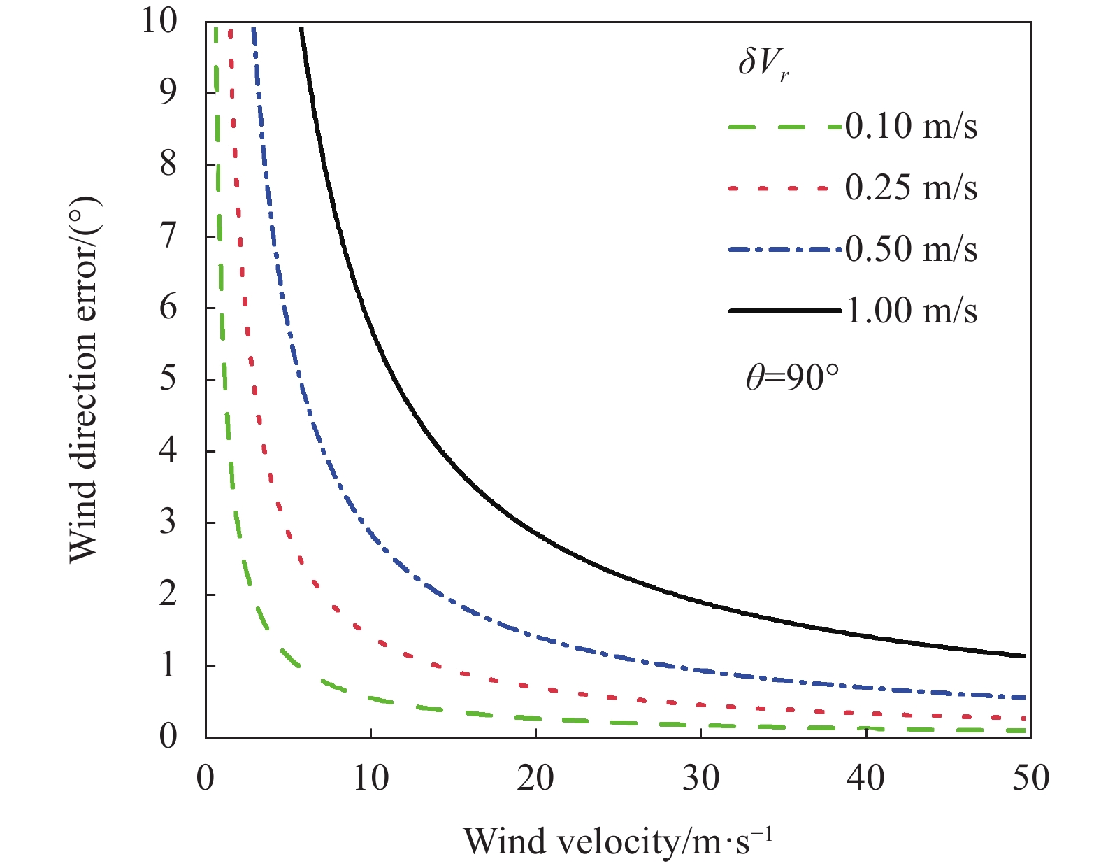
      再考虑大气风向探测误差,根据上式风向和风速误差的关系可知,风向探测误差与风速大小和径向风速测量数成反比,取系统径向风速测量数N=2,θ=90°时,可给出风场探测的风向误差随风速的变化,如图4所示。从图中可以看出:风向误差和风速大小成反比,在大气风速较大的情况下,风向误差趋于最小值,同时径向风速误差越大,风向探测误差也随之增大。当径向风速误差在1 m/s以下、风速大于15 m/s时,风向精度可以优于5°;对于风速小于10 m/s时,风向误差较大,风向探测误差大于5°。因此,在较大风速的情况下,激光风速仪的风向测量精度较高。

      Figure 4.  Wind direction detection error versus wind speed

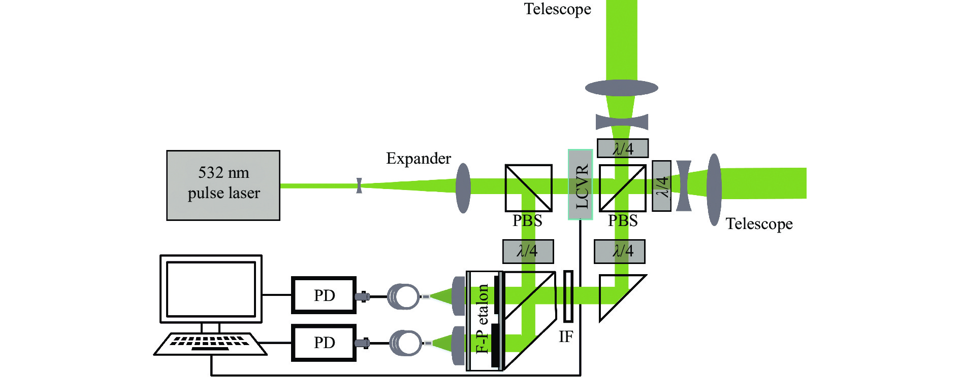
    • 激光风速仪在20 km海拔高度处工作,安装在飞艇浮空平台上。考虑到高空特殊的空间环境,散射光频率鉴别使用双通道腔长固定式F-P标准具,结构设计如图5所示,系统由激光器、收发望远镜、光电探测器和采集部分组成。

      Figure 5.  Schematic diagram of the fiber laser velocimetry

      出射激光经过一级扩束后,通过第一个偏振分光棱镜(PBS)的反射光,经光路由超快探测器接收以作为激光器出射光零频校准检测信号。而透射光经过LCVR进行激光偏振态的光束调制后,再通过第二个PBS,相互正交方向的线偏振光先后被第二个PBS透过和反射进入λ/4波片,再变为圆偏振光,然后被扩束镜整形后发射到两个不同方向的大气中。

      光子被大气中的氮气、水汽等分子相互作用后,产生后向散射的回波信号进入到接收望远镜,经λ/4波片后又变为线偏振光。由于回波信号光偏振方向发生了改变,两个相互正交方向的回波信号被第二个PBS先后反射、透射再进入同一接收光路,再经λ/4波片由线偏振光转为均匀的圆偏振光。然后经过窄带的干涉滤光片(IF)滤除部分天空背景光,接收信号光再被偏振分光棱镜按照50∶50比例分成两部分,分别经过F-P标准具的两个信号接收通道后到达聚焦透镜,通过单模光纤耦合将光信号送入光电探测器(PD),最后经光子计数卡采集,利用两个通道的不同光子强度探测宽谱信号的多普勒频移,最终得到接收光信号中含有的多普勒风速信息。

      激光发射光束偏振态的可控调制是偏振方法实现不同方向径向风速测量的基础,液晶可变延迟器由填满液晶(LC)分子溶液的透明液晶盒构成,可用作半波片。液晶盒壁的两个平行面镀有透明导电膜,在未加电压和施加交流电压两种情况下,LC分子会根据所施电压改变默认排列方向。通常状况下,液晶延迟器在高驱动电压下比在低驱动电压下的响应更快,当LCVR在两种电压之间切换时,下降时间(从低电压到高电压)比上升时间(从高电压到低电压)更快,LCVR有效通光孔径为20 mm,响应时间可达到ms级别。因此,改变施加电压可以主动控制液晶可变延迟器的延迟,从而转换光束探测方向,相位连续可控的LCVR具有驱动电压低、无机械转动、响应快、体积小等优点。

      所设计的系统采用电压驱动控制的LCVR、PBS和λ/4波片组合,共同组成光开光功能的光束转换设计方案,无需机械转动控制和同轴调节,使得整个光路更为简便高效,同时使用具有较高耦合效率的单模光纤,使其信号光子被探测器高效率接收,实现两个相互正交方向的径向风场探测。激光风速仪主要器件的选择参数见表1

      DeviceParameterValue
      LaserWavelength/nm532
      Repetition rate/kHz50
      Pulse energy/μJ10
      Divergence angle/mrad1.5
      Linewidth/MHz400
      Pulse time/ns5
      ExpanderBeam-expansion factor100
      TelescopeDiameter/mm100
      FilterFWHM/nm0.2
      EtalonPeak transmission0.77
      DetectorQuantum efficiency/@500 nm45%
      Max count rate/MHz10
      Counting cardTime resolution/ps200
      Input/channel2
      LCVRDiameter/mm20
      Transmission93%

      Table 1.  Key parameters of fiber laser velocimetry

    • 正如前文提及到,该系统的设计需求是尽可能准确地探测平流层飞艇的风场,而出射激光的频率稳定状态将会直接影响宽频信号多普勒频移的检测精度,以往传统的测风激光遥感系统的激光器都是采用单独的锁定通道来实现频率监测。

      对于激光器而言,获得单一的、稳定频率的出射激光是多普勒激光风速仪正常运转的首要条件。系统中利用激光出射光和大气散射回波信号进入接收机的到达时间差和高分辨率的光子计数卡结合的办法,高精度地监测出射光频率。采用的制冷式单光子探测器,在500 nm处的量子效率为45%,最大计数率为10 MHz,在环境温度25.9°条件下的暗计数为30 cps,探测性能优异。同时使用了一款高性能多功能的光子计数卡,在高采样率下也能保持很高的精度,具有2路通道输入,时间分辨率可达200 ps,能够记录12.5 GHz的突发计数率。单脉冲激光的时间序列对于系统的信号接收非常重要,零多普勒频率校准的工作时序图如图6所示。图中来自于激光器的时钟SYNC TTL高电平被用于同步距离门的电子学信号,单光子探测器和光子计数卡通过可编程的距离门控TTL高电平信号进行触发工作,所有的时序操作都可以通过工业台式机实现控制。

      Figure 6.  Data acquisition timing sequence

      在系统结构设计中,出射激光从第一个PBS经反射到达探测器的信号和经透射后从大气分子散射的回波信号有不一样的传输光路,系统设计的两者几何距离相差1.5 m,相应地信号到达单光子探测器的时间差为5 ns,由于光子计数卡的分辨率可以达到亚ns级,故零多普勒频率监测的设计思路是计数卡在极短的ns级时间内,能够采集到极少量的探测光子数,将二者的信号分开,从而确定出射激光的实时频率变化。

    • 图5所示,文中系统是参考了相干光路收发合置的探测方式设计的光路,采用单模光纤与自由空间相结合的方式对光信号进行传输。由激光器产生的532 nm脉冲光波为线偏振光,经中继光学预扩束系统对准直后的脉冲光进行扩束、压缩发散角,然后光束经过偏振态可调控的LCVR。当不加电压时,LCVR可看作λ/2波片,光束变为振动方向在垂直方向的线偏振光,加电压时,光束为振动方向在水平方向的线偏振光。LCVR与PBS、λ/4波片组合成为一个光开关,光束是垂直于PBS入射面振动的光,被PBS全部反射;光束是平行于PBS入射面振动的光,被PBS全部透射;然后反射光和透射光先后进入不同的探测光路中,再经光路中的λ/4波片将线偏振光变为圆偏振光,最后经二级扩束望远镜整形后发射到大气中。

      与大气分子相互作用产生的后向散射光被同一望远镜收集,此后向散射光已携带表征风速信息的多普勒频移。散射光再次通过λ/4波片,改变偏振态,此时的光波是线偏振光,平行于入射面振动的线偏振光被PBS全部透射,垂直于入射面振动的线偏振光被PBS全部反射。然后信号光依次通过λ/4波片、窄带IF以及F-P标准具的两个频率检测通道,再经光纤耦合进入单模光纤作为待测信号,最终光子信号到达接收探测器。

      整体光路中,激光器出射激光的发散角为1.5 mrad,光束直径为1 mm,中继光学预扩束系统和二级扩束系统放大倍率都为10倍,收发望远镜的直径为100 mm,光学接收机所选择的单模光纤NA为0.1,芯径为10 μm,F-P标准具的有效通光孔径为10 mm。对于光学接收机结构,一个不可回避的因素是光束的发散角,通过F-P标准具接收光路的几何关系,经计算得到接收回波信号光入射到达F-P标准具的光束发散角为0.2 mrad。

      相干光路的系统设计,无需调节同轴,具有结构简单、光路稳定性高等优点。同时由于太阳天空背景的影响,激光风速仪在白天工作的性能将会变差,而相干光路的设计结构决定了该系统无探测盲区,系统的接收视场角较小,以实现激光风速仪抑制强天空背景光,提高信号的接收效率,从而提升风场探测性能的目的。

    • 系统主要采用F-P标准具作为核心鉴频器件,F-P标准具的设计参数选取将会直接影响风速传感器的回波信噪比和探测误差,在考虑F-P标准具的参数设计时,以接收分子散射谱为基准,需要最优化的参数组合,F-P标准具的主要参数包括:自由谱间距(FSR)、两个边缘通道之间的峰值间隔以及谱宽(FWHM),这里从测量的灵敏度和误差方面进行分析,对F-P标准具的三个参数进行优化设计。

      相比米散射几百MHz的谱宽,大气分子散射谱要宽得多,可达到2 GHz。当分子信号进入F-P标准具频谱的邻级时,此时就会产生测量误差,所以分子散射谱必须在一个FSR内。由F-P标准具的速度灵敏度表达式可知,速度灵敏度与FSR和精细度(Finess)之间有相关关系。如果能够使大气分子后向散射信号和米后向散射信号的速度灵敏度相等,就可基本消除由高层大气极少量气溶胶成分的存在所带来的误差。

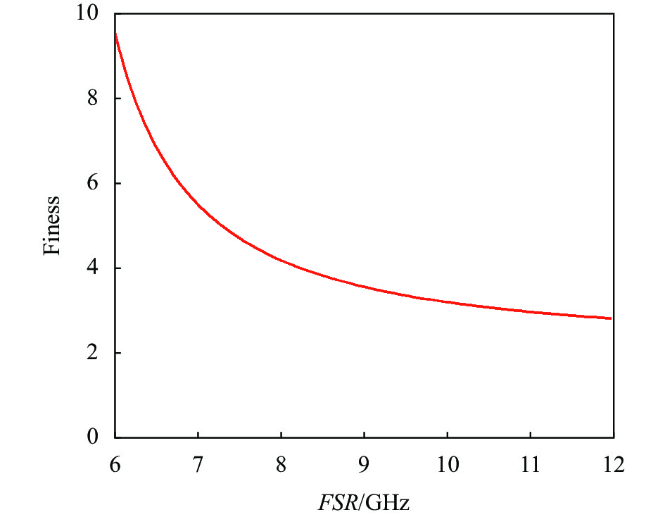
      在20 km处大气温度值为216.5 K的确定条件下,为了更准确得到Finess随FSR的变化趋势,首先在Mathcad程序中先设定Finess=6为精细度初始估计值。在风速为零的状态下,考虑发射激光频率严格稳定在两边缘通道透过率交点处的情况,大家知道${\theta _{Ray}}(F,F S R)$${\theta _{Mie}}(F,F S R)$仅与精细度FFSR两个量相关。要保证分子散射速度灵敏度${\theta _{Ray}}(F,F S R)$和米散射速度灵敏度${\theta _{Mie}}(F,F S R)$相等,即${\theta _{Ray}}(F,F S R)$=${\theta _{Mie}}(F,F S R)$为函数约束条件,那么必然有最佳的FFSR值存在。在程序中按照$f(F S R) = {\text{Find(Finess)}}$,其中${\text{Find(Finess)}}$为精细度求解函数,然后通过函数约束条件求解到初始估计值6附近的最佳精细度$f(F S R)$和它相关的FSR值,最终得到Finess和FSR的对应关系如图7所示。

      Figure 7.  Relationship between the finess and FSR of F-P etalon

      F-P标准具的谱宽计算公式为:

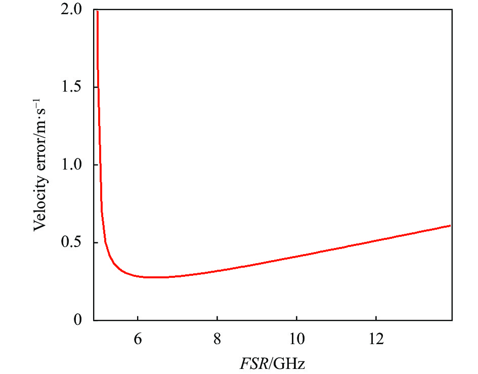
      图8给出了径向风速的测量误差随F-P标准具FSR的变化关系,由此可作为FSR选择的依据。从图中可以看到,当F-P标准具的FSR值从5 GHz增大到12 GHz的过程中,风速误差先迅速变小,再缓慢变大,同时在FSR=6.5 GHz处取得最小值,风速误差0.277 m/s处为曲线的最低点,此时找到对应的Finess=6.84,再根据公式(13)可进一步计算得到F-P标准具谱宽应为0.93 GHz。

      Figure 8.  Relationship between radial wind detection error and the FSR of F-P etalon

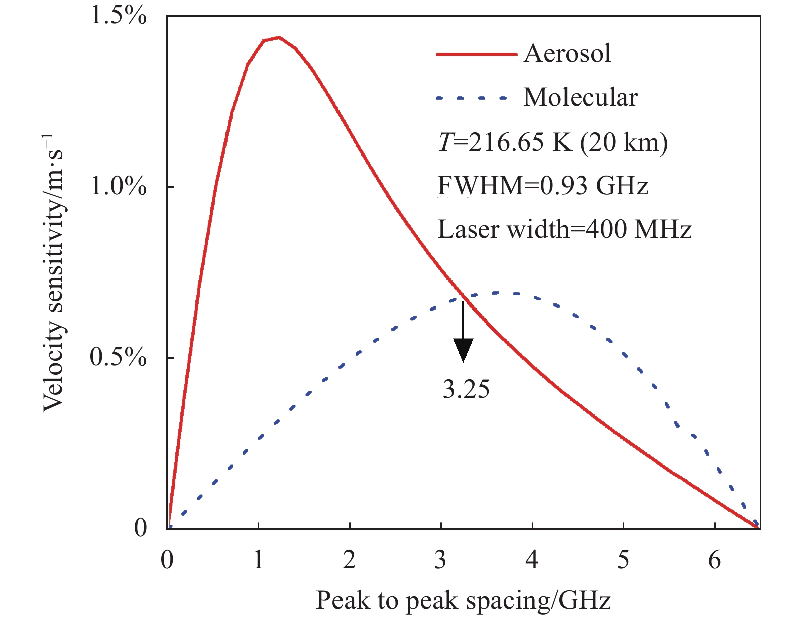
      在零风速时,当激光线宽为400 MHz,根据1976年美国标准大气模式,选取的F-P标准具边缘通道谱宽为0.93 GHz时,图9同时给出了零多普勒频移分子散射信号与气溶胶散射信号的速度灵敏度,以及它们随两个边缘通道F-P标准具的谱峰值间距的变化关系。从图中可以发现,在两条灵敏度曲线的交点处,即两者的灵敏度相等时,米散射信号的存在不仅不会使风速测量误差增大,而且米散射信号还将作为可以利用的有效信号来提高风速的测量精度,故最终F-P标准具两通道的峰值间距应取3.25 GHz。

      通过以上的讨论,F-P标准具的自由光谱间隔、谱宽和两个边缘通道的峰值间隔的优化参数得以确定,最终得到F-P标准具的FSR为6.5 GHz,FWHM为0.93 GHz,两个边缘通道的峰值间隔为3.25 GHz,Finess为6.84。F-P标准具的谱宽会影响灵敏度的同时也影响透过的标准具能量大小,从而影响系统的接收信号,因此,要获得较低的测量误差,必须要保证较高的系统回波信噪比。

      Figure 9.  Velocity sensitivity of the molecular and aerosol scattering signals varies with the frequency interval change of two edge channel etalons

    • 激光器工作波长的选取对平流层飞艇风速传感器的探测性能有着极其重要的影响,根据探测要求,该风速仪在海拔20 km处水平探测需达到500 m远的距离。根据激光雷达方程可知,影响探测系统回波光信号强弱的大气主要因子是探测高度处大气分子的后向散射系数,还有激光风速仪和探测距离间的大气透过率。针对在20 km探测高度而言,大气消光系数可认为是一个常数,并不随探测距离而改变。对于激光与大气的相互作用,后向散射系数与激光波长有着密切的关系,短波长的355 nm和532 nm更容易被高层大气散射,更适合高层信号的获取,长波长的1064 nm、1055 nm接收到的分子散射强度较弱,不易于获取探测信号。同时充分考虑到532 nm在系统光学装调、整体光学透过率、探测器量子效率以及激光器性能稳定性和成本等优势,以及更高的激光能量和光学效率参数保证,最终文中系统采用532 nm作为其探测波长。

      同时还要考虑系统的回波探测信噪比,可由下式表示:

      式中:m为累计脉冲数;$ {N_S}(\lambda ,r) $为系统接收到的大气后向散射光子信号;$ {N_B}(\lambda ) $为背景噪声光电子数。

      激光风速仪接收的是散射角为180°的后向散射信号,其信号的强弱与探测系统望远镜有效面积、大气分子密度、探测高度及距离等参数有关,系统探测到的距离r处的光子数为:

      式中:$ {T_L} $$ {T_R} $分别为系统的发射和接收光学效率;$ \eta $为单光子探测器的量子效率;h为普朗克常量;$ {E_0} $为单发激光脉冲能量;$ {A_R} $为接收光学系统望远镜的接收面积;$\; \beta (\lambda ,r) $为20 km高度处大气后向散射系数;$ \Delta r $为距离分辨率;$ \alpha $为20 km高度处的大气消光系数。

      系统接收到的背景光电子数可以表示为:

      式中:$ {I_B} $为大气的太阳光谱的单位波长辐亮度;$\varOmega$为望远镜的接收视场角;$ \Delta \lambda $为滤光片带宽。

      根据表1中给出的典型系统仪器参数,其中窄带干涉滤光片IF带宽取0.2 nm,系统主要的背景噪声来自大气对太阳光的散射,所以夜晚的天空背景光可以忽略不计,考虑白天最差的地表反射系数情况,对夜间和白天2种典型太阳光谱辐亮度分别取0和100 mW·m−2·nm−1·sr−1,累计5 ×10⁵个激光脉冲数,得到532 nm回波信号的信噪比随探测距离的变化关系如图10所示。从图中可以看出,白天和夜间的探测信噪比曲线在500 m距离内几乎重合,主要是由于系统指向水平探测方向,垂直于Z轴的天顶方向,得到的白天太阳背景光谱辐亮度值仍然很小。总体来看,在探测距离500 m处系统的回波信噪比仍然大于180,发射波长为532 nm的激光风速仪所选的系统参数满足白天和夜间较高回波信噪比的探测要求。

      Figure 10.  SNR curves of 532 nm in daytime and nighttime detection

    • 径向风速测量误差为风速的方差,它的计算公式可表示为:

      考虑选取的设计参数仿真系统的风速探测性能,利用光子累计的方法可提高系统的信噪比,从而减少风速测量误差。当信号累积时间为10 s (时间分辨率)时,系统的水平距离分辨率设置为100 m@50~500 m,计算得到不同风速条件下测量的径向风速测量误差随探测距离的变化如图11所示。从图中可知,风速越大,其径向风速测量误差也越大,当风速为100 m/s、探测距离为500 m时,风速测量误差为0.9 m/s,但综合来看在50~500 m的探测距离范围内,系统的风速误差都远小于1 m/s,可满足风速探测误差较低的需求。

      Figure 11.  Radial wind velocity error varying with detection distance at different wind velocities

    • 文中介绍了一种应用于平流层飞艇浮空平台的直接探测光纤激光风速仪的系统设计,并仿真分析了风场探测性能。为了减少受环境温度变化及震动干扰而造成F-P标准具的性能下降,使用固定腔长式的F-P标准具,同时优化了F-P标准具的设计参数,确定最佳的FSR为6.5 GHz,FWHM为0.93 GHz,两通道谱间距为3.25 GHz。在风场探测中,系统设计的径向风速探测数为2,径向风速误差在探测距离500 m以内小于1 m/s。在考虑不同大气风速的情况下,风速越大,风向探测误差越小。当平流层飞艇在小于10 m/s的风速条件下,风向探测误差大于5°;而在50 m/s的较大风速情况下,系统的风向探测精度优于2°。因此,设计的系统在近距离范围内(50~500 m)具有极低的探测误差、高分辨率、无盲区探测的优点,可满足于平流层飞艇激光遥感的风场探测目标。

Reference (19)

Catalog

    /

    DownLoad:  Full-Size Img  PowerPoint
    Return
    Return