


-
结构光三维测量技术是目前主流的三维测量方法,其具有非接触式测量、成像精度高、重构速度快等优点,被广泛地应用于工业自动检测、逆向工程、人体测量、航天航空等领域[1-3]。其基本原理是通过向被测元件投射结构光,采集经被测元件调制的图像,根据解算图像中的包裹相位得到被测元件的表面相位分布,由此实现面形重构。相位解算的精度将直接影响到物体最终的重构精度,所以在结构光三维测量中选用高精度标定方法[4]和相位解算方法十分重要。
相移法是最常用的相位测量方法,但通过相移法得到的是包裹相位,其范围在(0,2π],需要对包裹相位进行解包裹计算才能得到真实的相位分布。相位解包裹方法主要可分为空间相位解包裹和时间相位解包裹两大类[5-8]。空间相位解包裹只需任意一幅不特定时刻的包裹相位图就可以计算出绝对相位,但是该方法只能用于表面光滑且轮廓简单的物体,并且还要满足高信噪比的前提条件[9-12],这一系列的要求制约了空间相位解包裹的应用场景。
空间相位解包裹的本质是一种积分过程,任何一点的误差都会随展开过程演变成累积误差[13]。时间相位解包裹需要投影多个频率不同时刻的条纹图以确定绝对相位,相比空间相位解包裹,该方法每个像素点的相位是在时间轴上展开得到的,在空间上彼此孤立,展开过程不依靠展开路径和相邻相位信息避免了误差的传递。同时,时间相位解包裹方法具有展开结果稳定、过程简单、不会受到待测物体形貌复杂程度的影响等优点[14]。
多频外差解包裹作为最常用的时间相位解包裹算法,具有原理简单、解算精度高等优点。但在实际测量中,由于测量环境、物体表面特性、相机和投影仪的非线性误差等因素,在条纹级数取整过程会出现错误取整导致跳跃性误差的产生,因此使用多频外差方法时必须设法修正跳跃性误差。Cai等[15]利用Hilbert算法对相位误差进行补偿,对连续表面测量效果显著,但测量效率较低。雷志辉等[16]经过对多频外差原理的改进提出利用双频投影条纹的叠栅特性进行解包裹的方法,但该方法仅对双频外差法中出现的跳跃误差有效,对多频外差法效果并不理想。陈松林等[17]对雷志辉等人的方法加以改进,最终得到平滑无跳变的解包裹相位,但该方法对投影条纹有诸多约束条件,限制了条纹投影的灵活性。陈玲等[18]对多频外差解相后的展开相位进行分析,使用邻域像素点对误差处进行修正,但是大邻域的选取降低了条纹投影的分辨率且无法精准判断相位跳跃产生原因。
文中对多频外差解包裹原理进行了充分研究,对所得展开相位中跳跃性误差的产生原因进行了深入的分析讨论,提出一种多频外差相位校正方法,对由多频外差法解得的展开相位进行误差校正,并将校正前后的展开相位进行比较。
-
多频外差解包裹相位指将多个不同频率的条纹图像进行叠加,通过对叠加在一起的包裹相位进行求解,得到各个频率的绝对相位。最常用的多频外差解包裹方法是双频外差和三频外差。
-
双频外差原理如图1所示,向待测物体表面投射条纹节距分别为
$ p_{1} $ ,$ p_{2} $ 的两种正弦条纹图,为方便后续计算此处应保证$ p_{1}< p_{2} $ ,叠加后形成节距为$ p_{12} $ 的叠栅,对物体上任意一点,设其水平方向坐标为$ {x} $ ,对应的条纹级次分别为$ n_{1}、n_{2} $ ,则成立以下等式:式中:
$ N_{i} $ 代表条纹级次的整数部分;$ \Delta n_{i} $ 代表条纹级次的小数部分;$ \phi_{i} $ 代表对应条纹的包裹相位。
Figure 1. Dual frequency heterodyne principle
先以简单的双频外差为例分析其原理及误差产生原因,由公式(1)可推出:
将公式(3)代入功能等式(5)中,可得:
对于上述公式(6)~(8),由于
$ p_{1}、p_{2} $ 已知,$ \Delta n_{1} 、 \Delta n_{2} $ 可由公式(2)求得。故若能解出$ N_{1}-N_{2} $ 的值,便可求出$ n_{1}、n_{2} $ 。将展开后的绝对相位命为$ \varphi_{i} $ ,则可将绝对相位与包裹相位的关系表示为:下面分析误差的产生原因,先假设采集到的图像上的某点水平方向坐标为
$ {x} $ ,该点在$ [m, m+1) $ 级叠栅条纹中,即$ n_{12} \in[m, m+1) $ ,$ N_{12}=m $ ,结合公式(4)有:$x \in\left[\dfrac{m p_{1} p_{2}}{p_{2}-p_{1}}, \dfrac{(m+1) p_{1} p_{2}}{p_{2}-p_{1}}\right) $ 。故公式(8)可写为:
已知
$ \Delta n_{1}, \Delta n_{2} \in[0,1) $ ,所以$ \Delta n_{2}-\Delta n_{1} \in[-1,1) $ ,结合$ N_{\mathrm{i}} \in \mathrm{Z} $ ,公式(10)可改写为:设
$ N_{1}-N_{2}=k $ ,结合公式(11)对公式(10)分情况讨论,可得:结合公式(6)、(7)、(9),
$ \varphi_{i} $ 可表示为:在实际图像中,由于相邻像素点受环境中各类噪声影响,可能造成某一点处
$ \phi_{1}-\phi_{2} $ 出现2π误差,在公式(13)中可以看到,该误差在因子$ p_{1} /\left(p_{2}-p_{1}\right), p_{2} /\left(p_{2}-p_{1}\right) $ 的作用下被放大。结合公式(9)将条纹级数整数部分和小数部分分开计算:
式中:
${ floor }\{\;\}$ 表示向下进行取整。通过公式(14)可以将误差放大因子$ p_{1} /\left(p_{2}-p_{1}\right), p_{2} /\left(p_{2}-p_{1}\right) $ 去除,此时剩余误差项$ \phi_{1}, \phi_{2} $ 。 -
向物体投射三种不同节距的正弦条纹图,节距分别为
$p_{1},p_{2},p_{3}$ ,$ p_{1} $ 和$ p_{2} $ 叠加形成节距为$ p_{12} $ 的叠栅,同理$ p_{2} $ 和$ p_{3} $ 叠加形成节距为$ p_{23} $ 的叠栅,将$ p_{12} $ 和$ p_{23} $ 叠加形成节距为$ p_{123} $ 的叠栅,注意应保证$ p_{1}<p_{2}<p_{3} $ ,原理与双频外差相同。则:根据待测物体尺寸确定条纹投影范围,需满足待测物体在投影中心区域且被投影的条纹完全覆盖。由公式(15)可以计算出叠栅节距
$ p_{123} $ ,当$ p_{123} $ 略大于投影仪分辨率时,叠栅$ p_{123} $ 刚好能够覆盖整个视场,较为接近投影仪横向分辨率,视场内$ p_{123} $ 不足一个周期,即$ n_{123}<1, N_{123}=0, n_{123}=\Delta n_{123} $ 。由已经推导过的双频外差原理可知:公式(16)、(17)中
$ r=N_{12}-N_{23} $ ,$ N_{123}=0 $ ,故由公式(17)可求出绝对相位
$ \varphi_{12}, \varphi_{23} $ ,反推可得$ N_{12}, N_{23} $ ,再由公式(14)可解出$ \varphi_{1}, \varphi_{2}, \varphi_{3} $ 。 -
由上文推导可知,误差主要有两种,受测试环境、系统硬件(相机、投影仪)精度影响,使得条纹整数级
$ N_{12}\left(N_{23}\right) $ 取整错误,如导致$ N_{12}^{\prime}=N_{12}+1 $ ,这就会在展开相位$ \varphi_{1} $ 中发生幅值为${ floor }\left\{p_{2} /\left(p_{2}-p_{1}\right)\right\} \times 2 \pi$ 的跳跃性误差,$ \left(\phi_{1}-\phi_{2}\right) / 2 \pi $ 的误差值也会对展开相位造成幅值为2π的相位误差。 -
(1) 采集光栅投影后的图像,利用相移法求解出
$ p_{1}, p_{2}, p_{3} $ 的包裹相位,利用多频外差原理求解展开相位$ \varphi_{1}, \varphi_{2}, \varphi_{3} $ ;(2) 通过后一像素点相位幅值减当前像素点相位幅值计算展开相位的梯度,找出
$ \varphi_{i}(i=1,2,3) $ 中可能存在误差的可疑点,根据误差的幅值判断误差来源于$ N_{12}\left(N_{23}\right) $ 或$ \phi_{i}(i=1,2,3) $ 并确定误差的起始和终止像素点位置(连续误差像素点一般小于5个),确定来源于$ N_{12}\left(N_{23}\right) $ 后抹除跳跃性误差并对跳跃点处加以平滑;(3) 误差来源
$ \phi_{i} $ 时,通过对邻域像素点计算梯度确定误差的起始和终止像素点位置(连续误差像素点一般小于5个),判断该点处$ \phi_{1},\phi_{2},\phi_{3} $ 是否都发生相位突变,如果3个频率的展开相位在该点都有相位突变,则证明此处为物体表面的真实结构,在投影条纹的两侧会出现$ \varphi_{1} \approx \varphi_{2} \approx \varphi_{3} $ 的情况,投影时两侧条纹不属于测量区,故不作考虑;(4) 如果3个频率中有2个的展开相位在该点区域都有相位突变,则需要分情况讨论,如果有相位变化的两个展开相位在此点处的包裹相位值非常接近,(此处阈值设为π/10),认为此处属于相位误差,对该点进行
$ \pm 2 \pi $ 的修正,若此处两包裹相位值大于π/10,认为该区域解相正确;若仅有1个展开相位有相位突变,则认为此处属于解相位错误。以
$ \varphi_{1} $ 为例进行流程演示,设$ a $ 点为当前待检测像素点,$ b $ 点为$ a $ 点水平方向下一像素点,$m= { floor }\{b+1, b+5\}, n=m-1 $ ,具体流程图如图2所示。
Figure 2. Error correction flow chart
-
验证文中方法的有效性,对标准球进行三维测量。首先搭建三维测量系统,利用张正友标定法对系统进行标定。该实验使用basler a2A1920工业相机,分辨率为1920 pixel×1080 pixel,使用XGIMI公司 XG14V型号投影仪,分辨率为1920 pixel×1080 pixel,实验采集图像如图3所示。
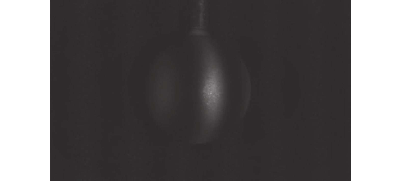
Figure 3. Images acquired in the experiment
实验采用三频外差、四步相移的方案,投影
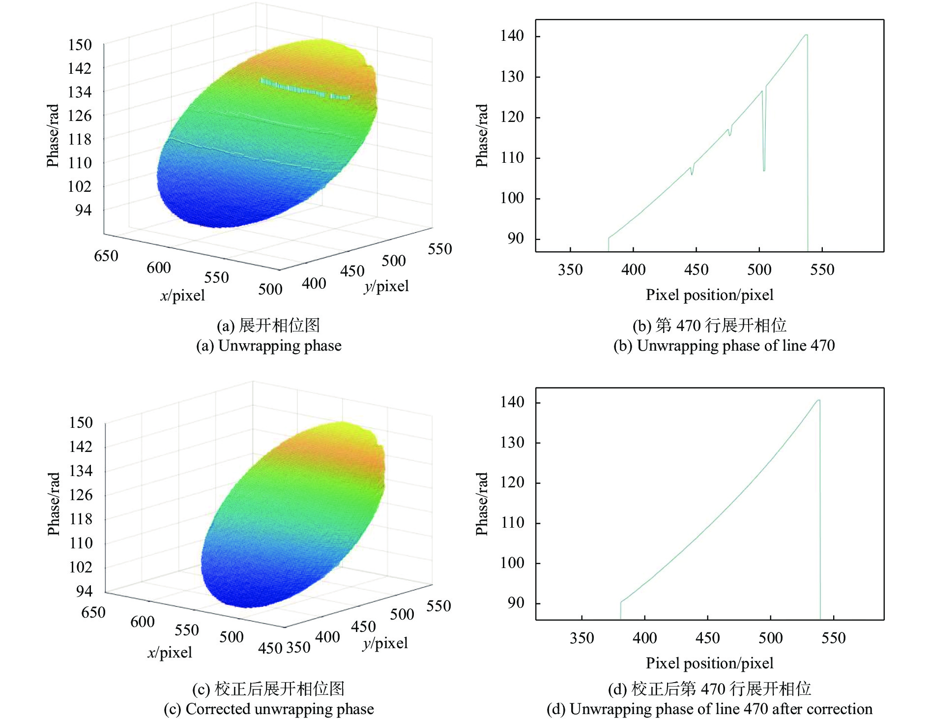
$ p_{1}=24, p_{2}=26, p_{3}=28 $ 的光栅条纹。利用参考文献[16]提出的改进后多频外差解包裹方法,对相机采集到的实验条纹图进行解包裹相位处理,得到展开相位$ \varphi_{1}, \varphi_{2}, \varphi_{3} $ ,其中$ \varphi_{1} $ 相位分布如图4(a)所示,可以明显观察到由展开相位幅值突变引起的带状错误解相位区域,其中包含由$ \left(\phi_{1}-\phi_{2}\right) / 2 \pi $ 的误差引起的幅值为2π的相位突变以及由条纹整数级次$ N_{12} $ 取整错误引起的幅值为${ floor }\left\{p_{2} /\left(p_{2}-p_{1}\right)\right\} \times 2 \pi$ 的相位突变。为精确确定展开相位误差的产生原因和误差所在像素点的位置,随机取$ \varphi_{1} $ 展开相位图的某一行进行观察分析,这里取展开相位$ \varphi_{1} $ 的第470行进行观察,如图4(b)所示,在第450个像素点和第475个像素点附近区域出现幅值约为2π的相位突变,证明在这两个区域内的像素点相位解包裹过程中由于$ \phi_{i} $ 的误差造成了错误的解相,在第504、505 pixel点处,相位出现了幅值较大的跳跃性误差,证明此区域内$ N_{12} $ 的取值发生错误,由$p_{1}=24, p_{2}=26$ 知,由$ N_{12} $ 错误取值导致的相位误差理论值为26π,实际由于环境噪声及其他因素,实际相位幅值误差为24.2π。图5所示为展开相位$ \varphi_{12} $ 的整数级次$ N_{12} $ ,在与图4(b)相位发生跳跃性误差的对应像素点处,展开相位$ \varphi_{12} $ 整数级次取整发生错误。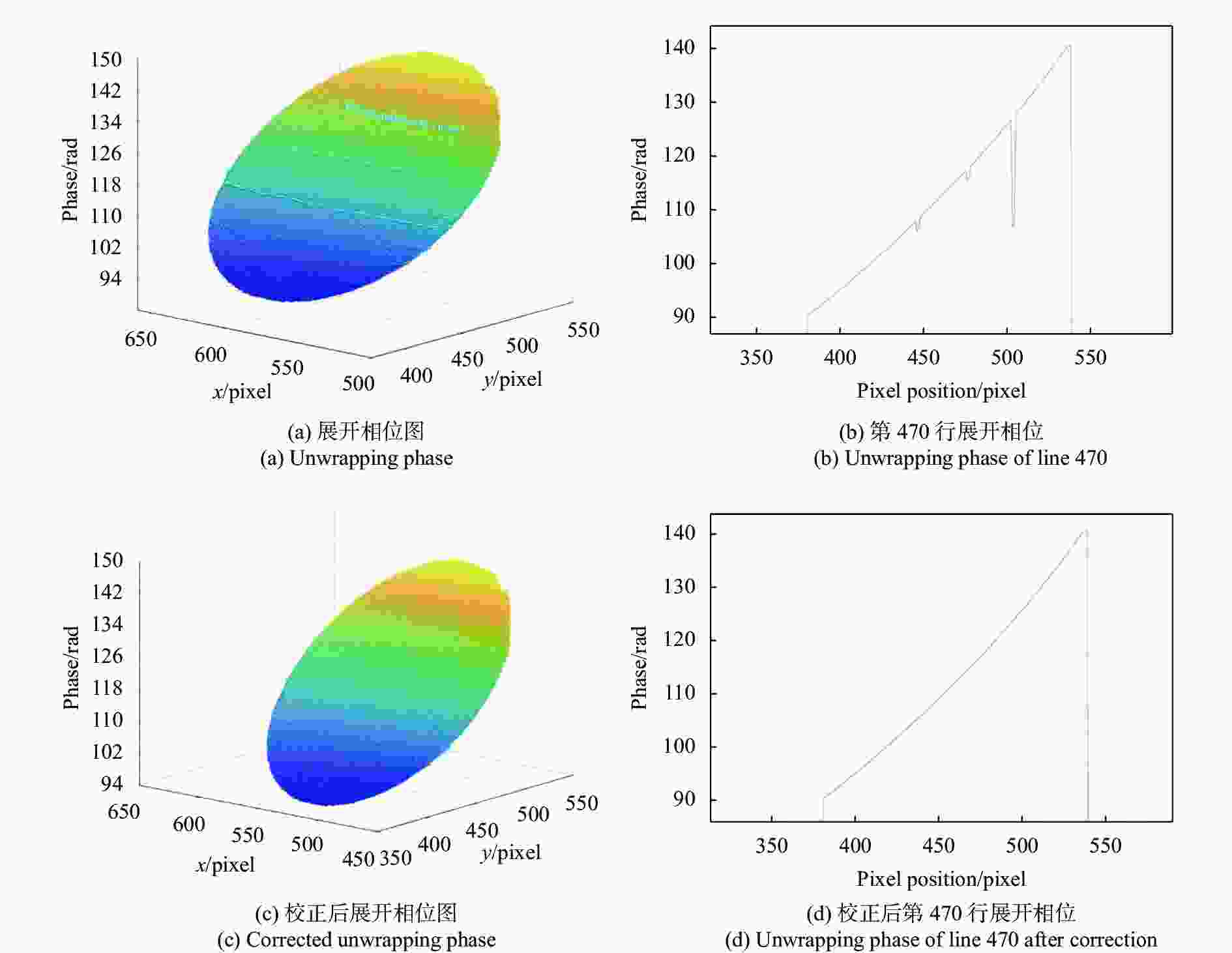
Figure 4. Unwrapping phase distribution before and after correction
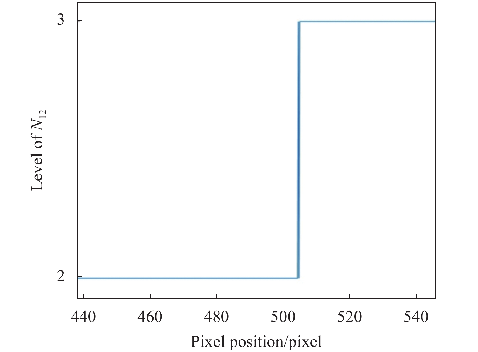
Figure 5. Integer level N12 of
$ \varphi_{12} $ 使用文中提出的误差校正算法对所得展开相位进行误差校正,得到修正后展开相位
$ \varphi_{1}^{\prime} $ ,相位分布如图4(c)所示,将图4(c)与图4(a)对比,可以观察到原相位分布图中出现的相位突变区域已被成功消除,相位误差被成功修复,取$ \varphi_{1}^{\prime} $ 第470行观察如图4(d)所示,对比图4(b),原展开相位图在对应像素点位置出现的突变相位区域被成功修复,校正后的展开相位过渡平滑无相位突变现象。为更加直观的观察校正前后测量效果,分别以修正前后的展开相位进行三维点云重建,结果如图6所示,图6(a)为相位修正前重建结果,图6(b)为相位修正后重建结果,在图6(a)中,可以观察到由解包裹相位错误导致的表面残缺区域,对比图6(b),校正后的展开相位的三维点云重建中将解相位误差引起的表面突变很好的修复,得到的表面形貌平滑,无表面高度突变区域。
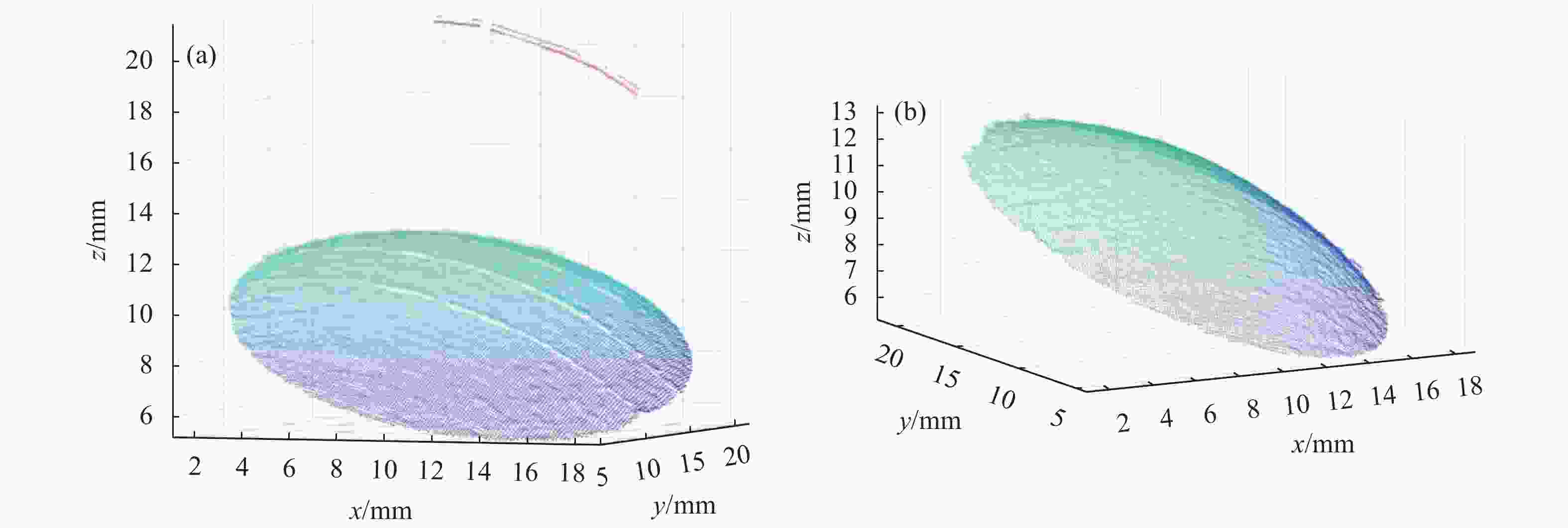
Figure 6. (a) 3D point cloud before correction; (b) 3D point cloud after correction
-
基于现有的多频外差解相位原理,在充分分析原理中跳跃性误差产生原因的基础上,提出了一种相位误差校正算法,针对引起误差的来源项
$ N_{12}\left(N_{23}\right) $ 和$ \Delta n $ 进行分析,通过多情况讨论确定误差类型并进行相位校正。实验结果表明,该方法可以精准定位误差产生区域并有效校正解包裹相位中产生的跳跃性误差,得到的展开相位平滑无跳变,三维点云重建无异常表面高度变化,验证了该校正方法的可行性。
Study of phase correction method based on multi-frequency heterodyne principle
doi: 10.3788/IRLA20220697
- Received Date: 2023-01-20
- Rev Recd Date: 2023-02-25
- Publish Date: 2023-05-25
Fund Project:
Shanghai 2021 "Science and Technology Innovation Action Plan" Natural Science Foundation (21ZR1483100)
-
Key words:
- error correction /
- multi-frequency heterodyne /
- unwrapping phase /
- jumping error
Abstract:


 DownLoad: