Volume 52 Issue 5
May  2023
Turn off MathJax
Article Contents

Li Ruolan, Wang Yang, Xu Qianzhi, Zhang Lei, Fu Yuegang. Relative illuminance improvement method of monocentric reflective mobile phone lens[J]. Infrared and Laser Engineering, 2023, 52(5): 20220763. doi: 10.3788/IRLA20220763
Citation: Li Ruolan, Wang Yang, Xu Qianzhi, Zhang Lei, Fu Yuegang. Relative illuminance improvement method of monocentric reflective mobile phone lens[J]. Infrared and Laser Engineering, 2023, 52(5): 20220763. doi: 10.3788/IRLA20220763

Relative illuminance improvement method of monocentric reflective mobile phone lens

doi: 10.3788/IRLA20220763
Funds:  Outstanding Young Talents Fund of Science and Technology Development Project in Jilin Province (20190103046JH)
  • Received Date: 2022-10-28
  • Rev Recd Date: 2022-12-09
  • Publish Date: 2023-05-25
  •   Objective   Enlarging the field of view of an optical system while maintaining good imaging quality is a difficult problem in modern optical design. The large field of view and high resolution of optical lenses are mutually restricted, and it is generally difficult to realize them at the same time. It requires complex structure design, expensive manufacturing, and large volume. Each surface of the monocentric lens is monocentric, and the curved imaging plane is also monocentric with each surface. The special structure enables it to achieve a large field of view and high resolution. It also has the advantages of simple structure, small size, and light weight. It is widely used in aerial remote sensing, security monitoring, photography, videography and so on, and may be first applied in miniaturized mobile phone lenses in the future. However, because the monocentric lens sets a conventional stop in the center to block the light beam of the off-axis field of view, when the field of view is larger, more light will be blocked, which causes greater vignetting, reduces the uniformity of illumination of the imaging plane, and affects the imaging quality. In order to improve the relative illuminance of the monocentric lens, a monocentric reflective mobile phone lens that uses a total reflection surface to control the light beam is designed.  Methods   A monocentric reflective mobile phone lens structure is designed in this paper. The initial structure is obtained by calculating the optical path of two reflective monocentric lenses (Fig.4). The optimized structure consists of a meniscus lens and a hemispherical lens, which are glued together using a low-refractive-index cement (Fig.5(a)). The spot for different fields of view of monocentric reflective lenses using conventional stop and virtual stop are simulated (Fig.6, Fig.8). Under different stop conditions, the relative illuminance curves of monocentric reflective lens are drawn (Fig.9).  Results and Discussions   The designed monocentric reflective mobile phone lens has a focal length of 2.7 mm, a maximum field of view of ±50°, a system F number of 1.8, a total length of 2.7 mm, and a maximum RMS radius of no more than 0.8 μm (Fig.5(b)). Under the conditions of conventional stop and virtual stop, the spot illuminance simulation of monocentric reflective lens is carried out. From the illumination diagrams of different fields of view, it can be seen that under the condition of conventional stop, the shape of the spot becomes ellipse when the field of view is 30°, and the minor axis of the ellipse is smaller when the field of view is 50° (Fig.6). Under the condition of virtual stop, the spot is circular in the 30° field of view, and the spot in the 50° field of view is rounder than the spot with the conventional stop. The relative illuminance curves of the mobile phone lens under the two kinds of stops are drawn, and the results show that the relative illuminance of the monocentric lens using the virtual stop is above 0.85, and the relative illuminance of the monocentric lens using the conventional stop is above 0.64 (Fig.9).  Conclusions   A monocentric reflective mobile phone lens is designed with a total reflection surface to restrict the light. Based on the establishment conditions of the virtual stop and the requirements of the mobile phone lens, an initial structure of the mobile phone lens based on the monocentric reflective lens is calculated. The focal length of the optimized system is 2.7 mm, the maximum field of view is ±50°, the system F# is 1.8, and the total length is 2.7 mm. The illuminance analysis results show that the relative illuminance of the mobile phone lens using the conventional stop gradually decreases with the increase of the field of view, and it is only 0.64 in the 50° field of view. However, the relative illuminance of a mobile phone lens with a virtual stop remains constant at 0° to 28° and is above 0.85 in the 50° field of view. The illuminance uniformity of the full field of view of the monocentric reflective lens using the virtual stop has been significantly improved, which can effectively improve the imaging performance of the system.
  • [1] Ma Wen. Research on optical system design of wide area high resolution camera axis [D]. Xi’an: Xi’an Technological University, 2020. (in Chinese)
    [2] Meng Xiangyue, Wang Yang, Zhang Lei, et al. Design of miniaturization and super wide angle monitor lens based on monocentric lens [J]. Infrared and Laser Engineering, 2018, 47(12): 1218002. (in Chinese) doi:  10.3788/IRLA201847.1218002
    [3] 沈阳. 基于同心球镜的超大视场光学系统研究[D]. 西安: 中国科学院大学(中国科学院西安光学精密机械研究所), 2018.

    Shen Yang. Research on super large field of view optical imaging technology based on monocentric lens[D]. Xi’an: University of Chinese Academy of Sciences (Xi’an Institute of Optics and Precision Mechanics, Chinese Academy of Sciences), 2018. (in Chinese)
    [4] Marks D L, Son H S, Kim J, et al. Engineering a gigapixel monocentric multiscale camera [J]. Optical Engineering, 2012, 51(8): 083202. doi:  10.1117/1.OE.51.8.083202
    [5] Pang W, Brady D J. Galilean monocentric multiscale optical systems [J]. Optics Express, 2017, 25(17): 20332-20339. doi:  10.1364/oe.25.020332
    [6] Pang W B, Brady D J. Field of view in monocentric multiscale cameras [J]. Applied Optics, 2018, 57(24): 6999-7003. doi:  10.1364/AO.57.006999
    [7] Schuster G M, Dansereau D G, Wetzstein G, et al. Panoramic single-aperture multi-sensor lightfield camera [J]. Optics Express, 2019, 27(26): 37257-37273. doi:  10.1364/OE.27.037257
    [8] Wang Yang, Wang Ning, Gu Zhiyuan, et al. Design of miniaturization mobile phone camera based on reflective monocentric lens [J]. Infrared and Laser Engineering, 2021, 50(11): 20210129. (in Chinese) doi:  10.3788/IRLA20210129
    [9] Agurok I P, Ford J E. Angle-invariant imaging using a total internal reflection virtual aperture [J]. Applied Optics, 2016, 55(20): 5345-5352. doi:  10.1364/AO.55.005345
    [10] Qu Enshi, Zhang Hengjin, Cao Jianzhong, et al. Discussion of illumination formula in optical design [J]. Acta Optica Sinica, 2008, 28(7): 1364-1368. (in Chinese) doi:  10.3788/AOS20082807.1364
    [11] Chen Chen, Hu Chunhai, Li Weishan, et al. Calculation method of relative illumination of lens image plane [J]. Acta Optica Sinica, 2016, 36(11): 1108001. (in Chinese) doi:  10.3788/AOS201636.1108001
    [12] Wang Yang, Meng Xiangyue, Zhang Lei, et al. Design of super wide-angle mobile phone lens based on monocentric lens [J]. Acta Optica Sinica, 2018, 38(10): 1022001. (in Chinese) doi:  10.3788/AOS201838.1022001
    [13] Huang Yunhan, Fu Yuegang, Zhang Guoyu, et al. Modeling and analysis of a monocentric multi-scale optical system [J]. Optics Express, 2020, 28(22): 32657-32675. doi:  10.1364/oe.406213
    [14] 王文生, 刘冬梅, 向阳, 等. 应用光学[M]. 武汉: 华中科技大学出版社, 2010.

    Wang Wensheng, Liu Dongmei, Xiang Yang, et al. Applied Optics [M]. Wuhan: Huazhong University of Science and Technology Publishing, 2010. (in Chinese)
    [15] Guo Zhiyuan, Li Jiancong, Chen Taixi, et al. Design of single-center and ultra-wide-angle mobile phone lenses [J]. Laser & Optoelectronics Progress, 2020, 57(7): 072204. (in Chinese) doi:  10.3788/LOP57.072204
  • 加载中
通讯作者: 陈斌, bchen63@163.com
  • 1. 

    沈阳化工大学材料科学与工程学院 沈阳 110142

  1. 本站搜索
  2. 百度学术搜索
  3. 万方数据库搜索
  4. CNKI搜索

Figures(9)  / Tables(1)

Article Metrics

Article views(127) PDF downloads(27) Cited by()

Related
Proportional views

Relative illuminance improvement method of monocentric reflective mobile phone lens

doi: 10.3788/IRLA20220763
  • 1. School of Optoelectronic Engineering, Changchun University of Science and Technology, Changchun 130022, China
  • 2. Military Representative Office of Shenyang Regional Military Representative Bureau of Army Armament Department in Changchun Region, Changchun 130000, China
Fund Project:  Outstanding Young Talents Fund of Science and Technology Development Project in Jilin Province (20190103046JH)

Abstract:   Objective   Enlarging the field of view of an optical system while maintaining good imaging quality is a difficult problem in modern optical design. The large field of view and high resolution of optical lenses are mutually restricted, and it is generally difficult to realize them at the same time. It requires complex structure design, expensive manufacturing, and large volume. Each surface of the monocentric lens is monocentric, and the curved imaging plane is also monocentric with each surface. The special structure enables it to achieve a large field of view and high resolution. It also has the advantages of simple structure, small size, and light weight. It is widely used in aerial remote sensing, security monitoring, photography, videography and so on, and may be first applied in miniaturized mobile phone lenses in the future. However, because the monocentric lens sets a conventional stop in the center to block the light beam of the off-axis field of view, when the field of view is larger, more light will be blocked, which causes greater vignetting, reduces the uniformity of illumination of the imaging plane, and affects the imaging quality. In order to improve the relative illuminance of the monocentric lens, a monocentric reflective mobile phone lens that uses a total reflection surface to control the light beam is designed.  Methods   A monocentric reflective mobile phone lens structure is designed in this paper. The initial structure is obtained by calculating the optical path of two reflective monocentric lenses (Fig.4). The optimized structure consists of a meniscus lens and a hemispherical lens, which are glued together using a low-refractive-index cement (Fig.5(a)). The spot for different fields of view of monocentric reflective lenses using conventional stop and virtual stop are simulated (Fig.6, Fig.8). Under different stop conditions, the relative illuminance curves of monocentric reflective lens are drawn (Fig.9).  Results and Discussions   The designed monocentric reflective mobile phone lens has a focal length of 2.7 mm, a maximum field of view of ±50°, a system F number of 1.8, a total length of 2.7 mm, and a maximum RMS radius of no more than 0.8 μm (Fig.5(b)). Under the conditions of conventional stop and virtual stop, the spot illuminance simulation of monocentric reflective lens is carried out. From the illumination diagrams of different fields of view, it can be seen that under the condition of conventional stop, the shape of the spot becomes ellipse when the field of view is 30°, and the minor axis of the ellipse is smaller when the field of view is 50° (Fig.6). Under the condition of virtual stop, the spot is circular in the 30° field of view, and the spot in the 50° field of view is rounder than the spot with the conventional stop. The relative illuminance curves of the mobile phone lens under the two kinds of stops are drawn, and the results show that the relative illuminance of the monocentric lens using the virtual stop is above 0.85, and the relative illuminance of the monocentric lens using the conventional stop is above 0.64 (Fig.9).  Conclusions   A monocentric reflective mobile phone lens is designed with a total reflection surface to restrict the light. Based on the establishment conditions of the virtual stop and the requirements of the mobile phone lens, an initial structure of the mobile phone lens based on the monocentric reflective lens is calculated. The focal length of the optimized system is 2.7 mm, the maximum field of view is ±50°, the system F# is 1.8, and the total length is 2.7 mm. The illuminance analysis results show that the relative illuminance of the mobile phone lens using the conventional stop gradually decreases with the increase of the field of view, and it is only 0.64 in the 50° field of view. However, the relative illuminance of a mobile phone lens with a virtual stop remains constant at 0° to 28° and is above 0.85 in the 50° field of view. The illuminance uniformity of the full field of view of the monocentric reflective lens using the virtual stop has been significantly improved, which can effectively improve the imaging performance of the system.

    • 大视场的光学系统不管是军事领域还是民用领域中都有着广泛的应用 [1],但是大视场光学系统存在结构复杂、镜片多、体积大等问题,而且视场越大,由于存在渐晕,相对照度往往更低。同心透镜具有对称性,可消除大部分像差[2-3],一些大视场高分辨率的镜头采用了该种光学结构形式[4-5]。2018年,Wubin Pang等人设计了一种能够实现360°全景拍摄的相机,该相机的物镜采用了同心透镜 [6]。2019年,Glenn M. Schuster等人设计了一种155°视场的全景光场相机,也采用了同心透镜[7]。在同心结构基础上,为了进一步缩小体积, 2021年,王洋等人设计一款同心反射式手机镜头,F数为1.8,最大视场角100° [8],全视场相对照度0.64以上。

      为了解决同心透镜轴外视场像面照度不均匀的问题,2016年,Joseph E. Ford等[9]在同心透镜中心的透镜表面加入一层低折射率胶合剂,边缘光线在胶合剂面上的入射角大于临界角时将发生全内反射,形成一个虚拟的光阑面,明显降低了系统的渐晕。

      在Joseph E. Ford的理论基础上,文中将该方法应用于反射式同心透镜,利用全反射条件建立了虚拟光阑,通过光路计算得到一种反射式同心透镜的手机镜头初始结构,优化后的系统F数1.8,焦距2.7 mm,最大视场角±50°,并且分别在传统孔径光阑和虚拟光阑的条件下对该系统进行照度分析。

    • 大视场光学系统的渐晕会影响像面照度均匀性,轴外视场的像面照度遵循余弦四次方的规律进行衰减[10-11],视场角越大,像面照度越低,导致像面照度不均匀。

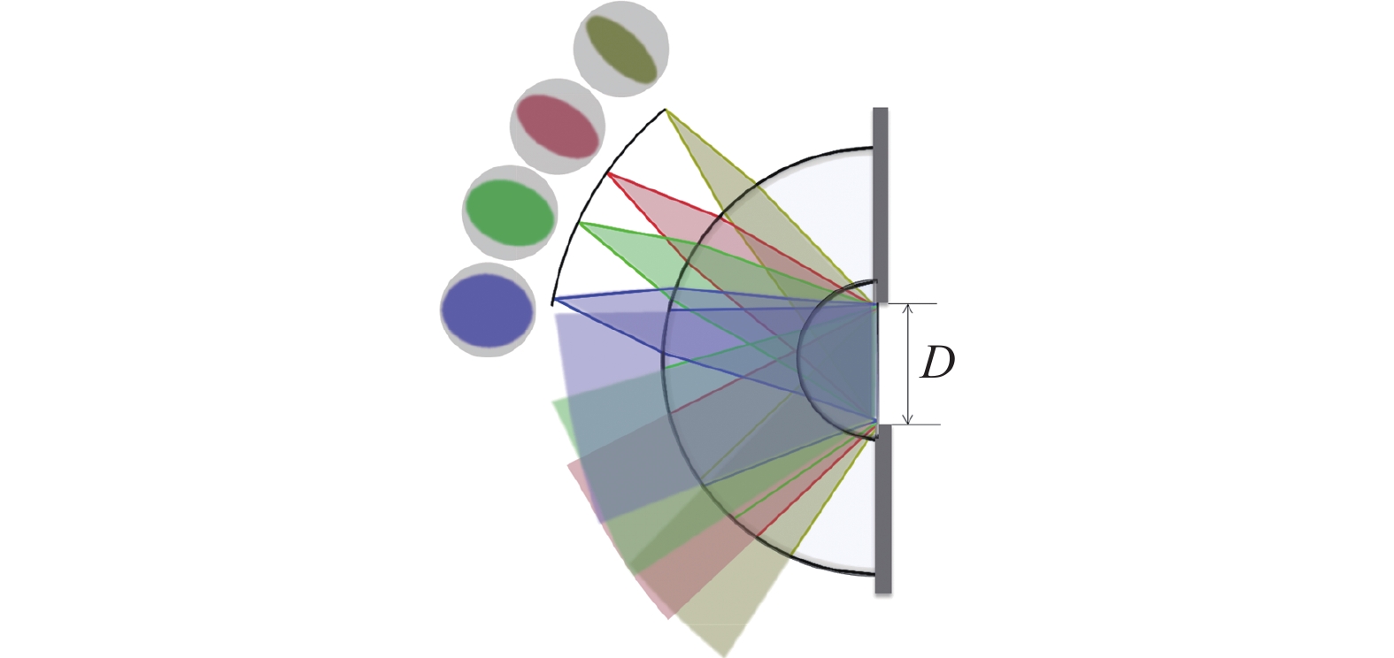
      图1所示为一个同心反射式手机镜头全视场的能量分布图,由于轴外视场实际入瞳孔径为轴上视场垂轴方向的入瞳孔径在轴外视场垂轴方向上的投影,呈视场角余弦乘积的关系,因此大量轴外光线被阻拦,使轴上到达像面的光束宽度大于轴外视场,产生渐晕现象,导致整个像面照度分布不均匀[12-13],影响光学系统的成像性能。

      Figure 1.  Vignetting of reflective monocentric lens

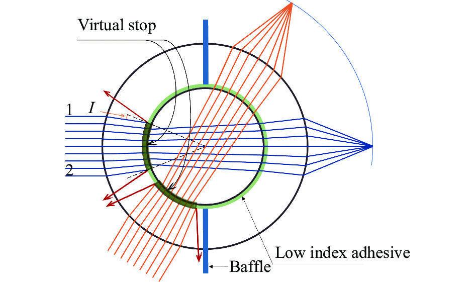
      在同心透镜的两片透镜之间注入某种胶合剂,其折射率低于两边透镜的折射率,并在中心透镜处设置挡板避免杂散光。如图2所示,轴上视场的上边缘光线1由第一片透镜入射至胶层时,即从光密介质入射到光疏介质,如果入射角I满足临界条件,将发生全内反射[14],光线全部返回,无法到达像面,下边缘光线2也是如此。同理,对于轴外视场也存在这种情况,这样,所有入射角大于临界角的光线都会被遮拦,相当于在两片透镜之间形成了一个“虚拟”的孔径光阑对光束进行控制,称之为 “虚拟光阑”。

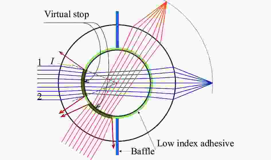
      Figure 2.  Monocentric lens with virtual stop
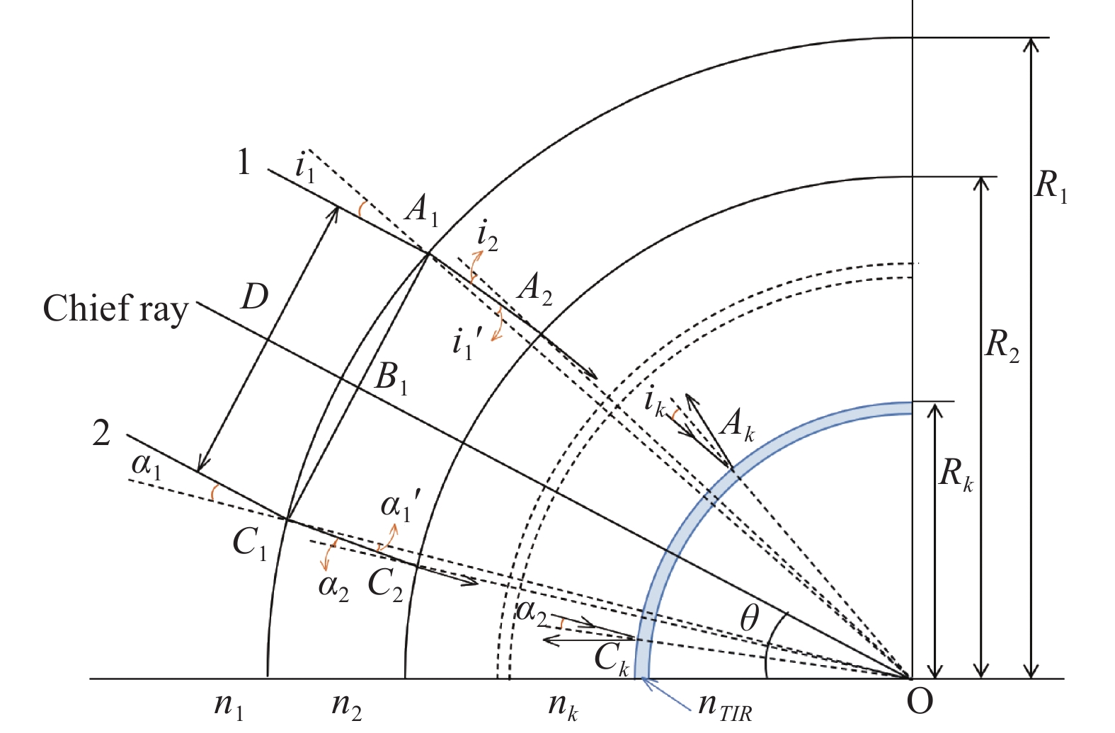
      图3所示,视场角为$ \theta $的平行光束,入射光束宽度为D,同心透镜内的k个表面同心,任何角度入射的主光线都可以看作光轴,则上下边缘光线1、2关于光轴对称。

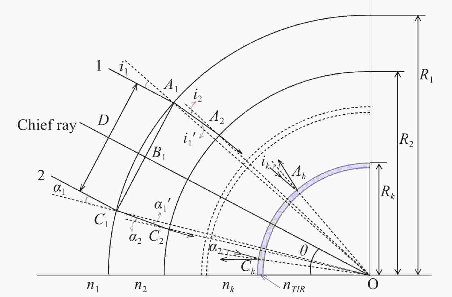
      Figure 3.  Monocentric lens ray tracing

      在△$ O{A_1}{B_1} $中:

      在点$ {A_1} $处,根据折射定律有:

      在△$ O{A_1}{A_2} $中,根据正弦定理有:

      以此类推:

      当光束的边缘光线1在第k个面处达到临界角的条件时将发生全反射,根据全反射临界角公式有:

      可得:

      同理:

      若透镜在空气中,可得到光束宽度:

      可知,使用虚拟光阑的同心透镜,入射光束宽度D只与内球的半径和胶层折射率有关,而与视场角无关,可以消除系统渐晕。

    • 根据市场上手机镜头总长和工作距的要求[15],参考笔者课题组设计的反射式同心透镜与虚拟光阑的建立条件,确定手机镜头的参数如表1所示。

      ParameterValue
      Waveband/nm486-656 (F, d, C)
      Relative aperture1/1.8
      Full field of view/(°)100
      Focal length/mm2.7
      Total length/mm$ \leqslant $2.7
      Back focal length/mm$ \geqslant $0.5

      Table 1.  Optical design parameters
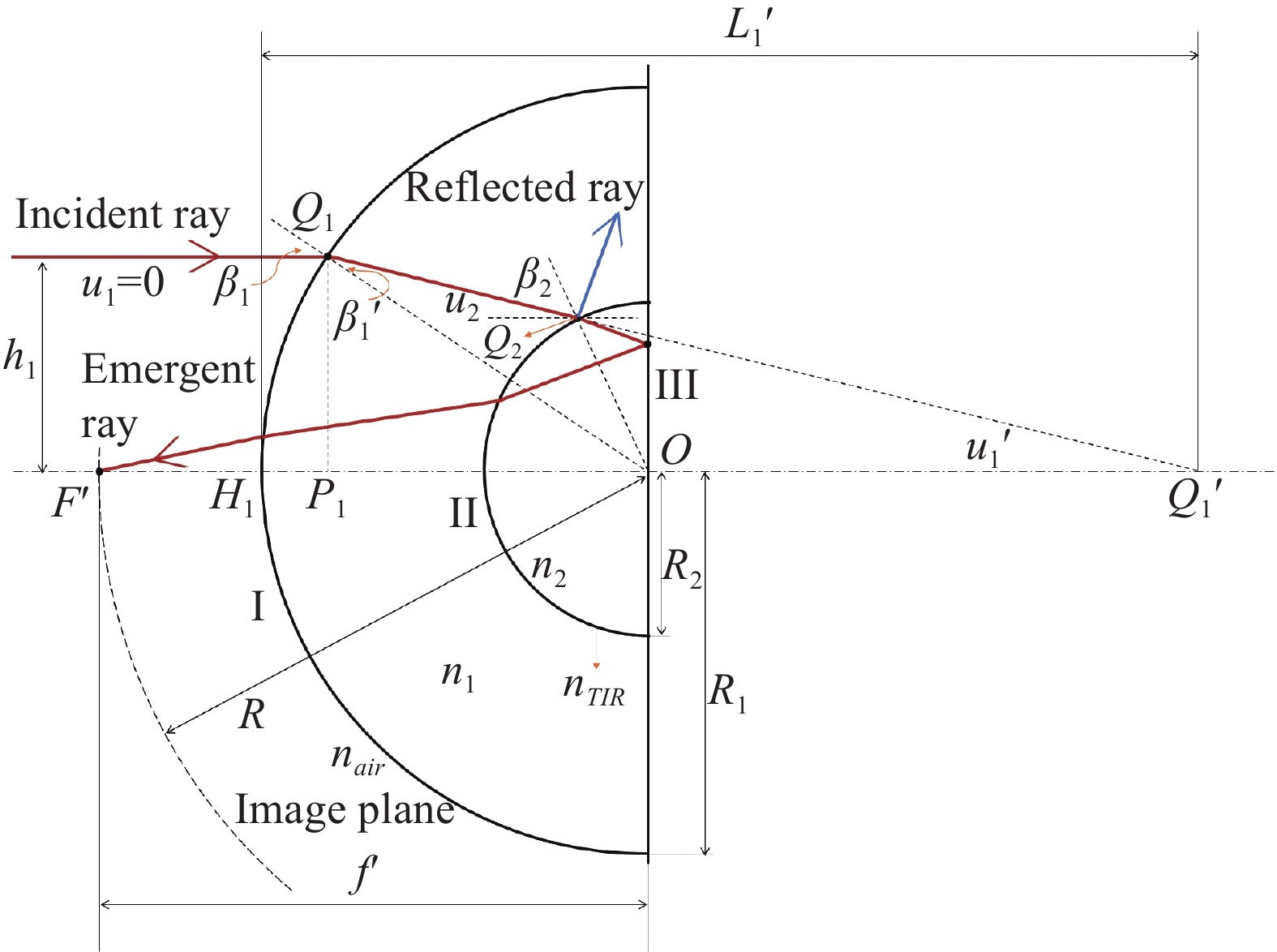
      图4所示,两片透镜中间设置了低折射率胶层,过同心透镜中心点$ O $且垂直于反射面的直线作为光轴,引出一条投射高度为$ {h_1} $的平行于光轴的光线,经过四次折射和一次反射,交于光轴上的点为焦点$ {F'} $,光学系统焦距为$ {f'} $,角度、半径和折射率的定义如图4所示。

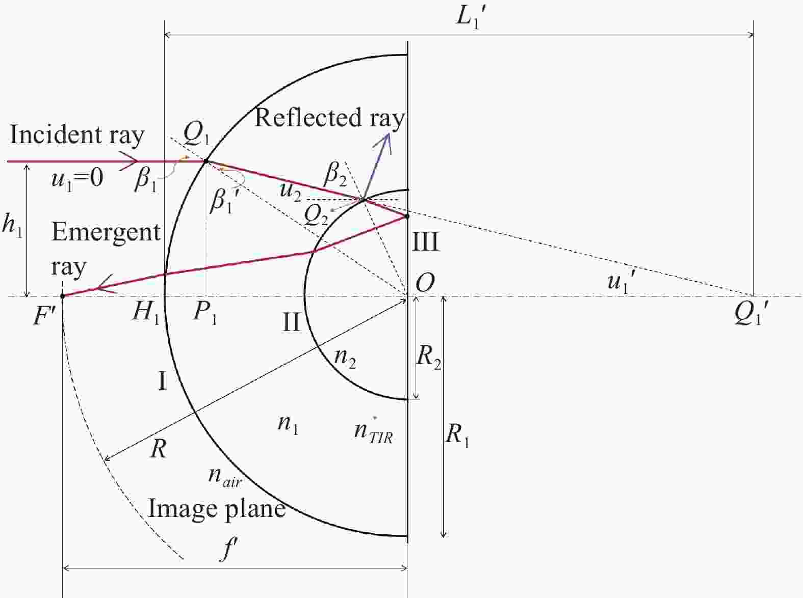
      Figure 4.  Optical path diagram of monocentric reflective lens

      表面Ⅰ与光轴交点为$ {H_1} $,高度为$ {h_1} $的光线与表面Ⅰ的交点为$ {Q_1} $,入射角为$ {\;\beta _1} $,出射角为$ \;\beta _1' $,入射光孔径角为$ {u_1} $,过点$ {Q_1} $做光轴的垂线交光轴于$ {P_1} $点,出射光的延长线与光轴交于点$ Q_1' $。入射光经过表面Ⅰ折射后交表面Ⅱ于点$ {Q_2} $,入射角为$ {\;\beta _2} $。经反射面Ⅲ反射,再经两次折射与光轴交于点$ {F'} $,即像方焦点。在$ \Delta O{P_1}{Q_1} $中:

      $ {P_1} $处,根据折射定律有:

      表面Ⅰ的像方孔径角$ u_1' $$ {\;\beta _1} $$ \;\beta _1' $的关系为:

      $ {H_1}Q_1' = L_1' $,即光线经表面Ⅰ折射后的像距:

      根据过渡公式,在实际光路计算中有:

      中间胶层选用美国Norland生产的胶合剂NOA1315,设其折射率为$ {n_{TIR}} $,当光线在胶合层发生全反射时,根据全反射条件有:

      联立公式(10)~公式(14),可以得到:

      同心透镜像面也与各表面同心,所以像面半径
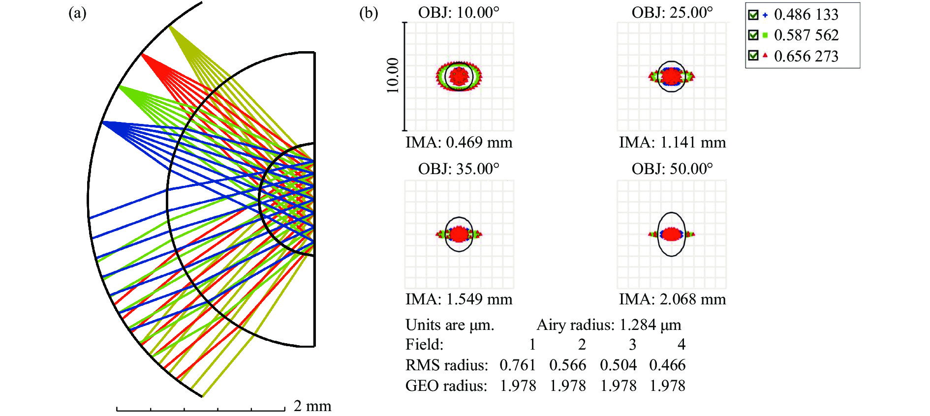
$ R $即为同心透镜焦距$ {f'} $。根据以上条件计算,表面Ⅰ的半径$ {R_1} $为1.9 mm,表面Ⅱ的半径$ {R_2} $为0.57 mm,初始结构经过优化后得到$ F $数为1.8、焦距为2.7 mm、总长为2.7 mm的同心反射式手机镜头,结果如图5(a)所示。由于同心反射式透镜的结构特点,轴上部分视场不可见,该设计的视场范围为10°~50°,系统的点列图结果如图5(b)所示,四个视场的弥散斑RMS半径最大值为0.761 μm,接近衍射极限。

      Figure 5.  (a) Layout and (b) spot diagram of mobile phone lens after optimization

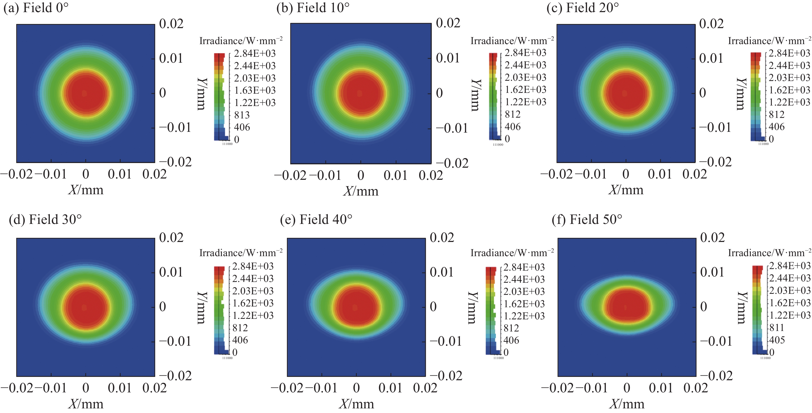
    • 为清晰地观察不同视场的光斑变化,对结构进行非序列光线追迹,光源和接收器视场角为50°,调整光源和接收器的位置和角度进行光线追迹,软件仿真分析可得到0°~50°视场的光斑照度(该结构实际有效视场为10°~50°,文中为了方便数据处理,0°~10°视场的仿真数据也在图中给出)。如图6所示,随着视场的增大,光斑形状逐渐改变,相应的照度也逐渐降低,其中50°边缘视场的照度衰减为中心视场照度的0.64倍。

      Figure 6.  Spots of reflective monocentric mobile phone lens using conventional stop

    • 建立虚拟孔径光阑的同心反射式透镜模型如图7所示,设置了孔径较大的挡板用于遮挡其他杂散光。调整光源和接收器的位置及角度,得到不同视场的光斑如图8所示。0°~35°视场的光斑半径始终保持在0.015 mm, 从40°视场开始,光斑形状逐渐发生变化,当视场增大至50°时,相对照度在0.85以上,得到的光斑相比图6中50°视场的光斑更加圆整。

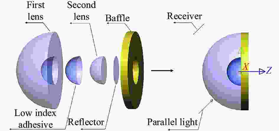
      Figure 7.  Reflective monocentric mobile phone lens model using virtual stop

      Figure 8.  Spots of reflective monocentric mobile phone lens using virtual stop

    • 采用两种不同光阑的手机镜头的相对照度曲线如图9所示,为了方便进行结果比较,同心反射式结构的仿真结果视场也从0°开始,但是实际有效的成像视场角为10°~50°。传统孔径光阑的手机镜头相对照度如曲线1所示,采用虚拟光阑的手机镜头相对照度如曲线2所示,曲线3为一相同参数的传统广角镜头相对照度。结果表明,使用传统孔径光阑的同心反射式手机镜头随着视场的增大,相对照度平缓下降,渐晕逐渐加大,最大视场相对照度为0.64,使用虚拟光阑的同心反射式手机镜头,在0°~28°视场的相对照度保持不变,最大视场的相对照度在0.85以上,采用基于全内反射的虚拟光阑进行光束限制,可有效提升系统像面的照度均匀性,改善成像性能。

      Figure 9.  Relative illumination

    • 文中对同心透镜相对照度的改善方法进行了研究,通过在反射式同心透镜中设置全内反射面建立虚拟光阑以减小渐晕。结合手机镜头要求,在全内反射的条件下对两片反射式同心透镜进行光路计算,得到了系统的初始结构,优化后的手机镜头焦距为2.7 mm,F数为1.8,最大视场角为±50°。此外,分析了使用传统孔径光阑和虚拟光阑的两种同心反射式手机镜头的相对照度,分析结果表明,采用虚拟光阑的手机镜头在0°~28°视场的相对照度保持不变,最大视场的相对照度在0.85以上,而采用传统孔径光阑的手机镜头最大视场的相对照度仅为0.64,可见虚拟光阑的选用可以改善同心透镜像面的照度均匀性。文中的方法不仅适用于手机镜头的设计,也可应用于其他同心结构的大视场高成像性能的小型光学镜头设计中。

Reference (15)

Catalog

    /

    DownLoad:  Full-Size Img  PowerPoint
    Return
    Return