Volume 52 Issue 12
Dec.  2023
Turn off MathJax
Article Contents

Qiu Peng, Zou Sicheng, Zhang Xiaoming, Wang Jianfeng, Lin Qin, Jiang Xiaojun. Study on performance testing techniques for astronomical optical cameras[J]. Infrared and Laser Engineering, 2023, 52(12): 20230316. doi: 10.3788/IRLA20230316
Citation: Qiu Peng, Zou Sicheng, Zhang Xiaoming, Wang Jianfeng, Lin Qin, Jiang Xiaojun. Study on performance testing techniques for astronomical optical cameras[J]. Infrared and Laser Engineering, 2023, 52(12): 20230316. doi: 10.3788/IRLA20230316

Study on performance testing techniques for astronomical optical cameras

doi: 10.3788/IRLA20230316
Funds:  National Natural Science Foundation of China (12003077); National Key Research & Development Program of China (2020YFA0406501); Specialized Research Fund for State Key Laboratories
  • Received Date: 2023-05-29
  • Rev Recd Date: 2023-07-17
  • Available Online: 2023-12-22
  • Publish Date: 2023-12-22
  •   Objective  Cameras is a critical component of an optical telescope observation system, and their performance significantly affects the quality and efficiency of astronomical observations. Acquiring camera performance parameters is beneficial in enhancing precision and efficacy of astronomical observations. Numerous worldwide photosensitive chips and camera manufacturers have devised their own performance to test standards based on their experience, to make it difficult to compare products from different manufacturers based on their performance parameters. Although camera performance test can be conducted according to the EMVA1288 standard, and data sheets conforming to EMVA1288 standard can be provided, the standard primarily caters to the machine vision industry cameras, and some of the performance test settings are incompatible with the needs of astronomical optical cameras. Consequently, research on testing technology for astronomical optical cameras is imperative.   Methods  In astronomical optical observations, the common used cameras are CCD (Fig.1) and CMOS (Fig.2). After analyzing the requirements of astronomical optical observations, the performance test items for astronomical optical cameras are determined to be gain, readout noise, full well capacity, dynamic range, linearity, bias stability, pixel readout noise statistics, photo response non-uniformity (PRNU), and dark current. The photon transfer curve (PTC) method and so on are selected for testing performance items, and definitions and testing methods for each item are explained. In order to verify the feasibility of this set of test items, test methods, test experiments, and data processing methods, the Andor Marana sCMOS and Andor iKon-L 936 CCD cameras (Fig.4) are tested in the laboratory using a testing system set up on a dark optical platform (Fig.5). The gain, readout noise, full well capacity, linearity, bias stability, pixel readout noise statistics, dynamic range, PRNU, and dark current of the sCMOS camera's 12-bit setting and CCD camera's 1 MHz 4× setting are tested, respectively.   Results and Discussions   A series of performance tests were conducted on the CCD and sCMOS cameras in a laboratory, obtaining performance parameters for the sCMOS 12-bit and the CCD 1 MHz 4× settings (Tab.4): gain, readout noise, full well capacity (Fig.6, Fig.7), linearity (Fig.8, Fig.9), bias stability (Fig.10), pixel readout noise statistics (Fig.11), dynamic range, PRNU, dark current (Fig.12, Fig.13, Fig.14). By comparing the performance test results of the two cameras, the Marana sCMOS 12-bit setting showed approximately half lower readout noise, 17 times higher dark current, 3 magnitude lower dynamic range, and twice as high PRNU compared to the iKon-L936 CCD 1 MHz 4× setting. Both cameras demonstrated high linearity and bias stability. The sCMOS camera exhibited glow, making it unsuitable for long-exposure observations. Through the laboratory tests of the sCMOS and CCD cameras, the performance parameters of cameras were obtained, and the feasibility of the testing items, testing methods, testing experiments, and data processing methods were verified.   Conclusions  Cameras are essential components of optical telescope observation systems. Acquiring camera performance parameters plays a significant role in formulating astronomical observation plans, adjusting observation strategies, data processing, and diagnosing faults. To enhance the accuracy and efficiency of astronomical optical observations, research on the performance testing of astronomical optical cameras has been conducted. By introducing CCD and CMOS cameras commonly used in astronomical optical observations and analyzing the performance requirements of cameras in astronomical optical observations, camera performance testing items, testing methods, testing experiments, and data processing methods have been established. These testing items include gain, readout noise, full well capacity, dynamic range, linearity, bias stability, pixel readout noise statistics, PRNU, and dark current.   To validate the feasibility of this methodology, a detection experiment was constructed based on the defined testing items, testing methods, testing experiments, and data processing methods. A comparative test was conducted using the Andor Marana sCMOS and Andor iKon-L936 CCD cameras to verify the testing items, methods, and data processing methods. Through performance testing experiments on the cameras, the feasibility of the testing items, testing methods, testing experiments, and data processing methods was confirmed. This research enables testing of all settings of a camera, allowing for the acquisition of performance parameters across the entire settings.   The proposed method facilitates comparisons between different settings of the same camera or between different cameras, assisting users in selecting cameras or cameras settings that better suit their observational needs, thereby obtaining better observation data. Regular performance testing of cameras can be conducted, and a comprehensive database of performance parameters throughout the camera's lifecycle can be established. This database would facilitate the management of camera health status and diagnosis of faults in the observation system.
  • [1] European Machine Vision Association. EMVA Standard 1288: Standard for Standard for Characterization of Image Sensors and Cameras. Release 3.1[S]. Barcelona: European Machine Vision Association, 2016.
    [2] 毛忠辉. CMOS图像传感器成像性能测试技术研究[D]. 中国科学院大学, 2022.

    Mao Zhonghui. Study on imaging performance test technology of CMOS image sensor[D]. Changchun: University of Chinese Academy of Sciences(Changchun Institute of Optics, Fine Mechanics and Physics, Chinese Academy of Sciences), 2022. (in Chinese)
    [3] 盆晓敏. 基于EMVA Standard 1288的CMOS图像传感器测试系统研究[D]. 哈尔滨工程大学, 2015.

    Pen Xiaomin. The research of CMOS image sensor testing system based on EMVA standard 1288[D]. Harbin: Harbin Engineering University, 2015. (in Chinese)
    [4] 王祖军, 薛院院, 姚志斌, 等. 基于EMVA1288标准的图像传感器辐照效应参数测试系统的研制[J]. 半导体光电, 2017, 38(04): 515-520.

    Wang Zujun, Xue Yuanyuan, Yao Zhibin, et al. Development of image sensor radiation effect parameters testing system based on EMVA1288 standard [J]. Semiconductor Optoelectronics, 2017, 38(4): 515-520. (in Chinese)
    [5] 罗志远, 许骏, 刘黎明, 等. 天文CMOS相机测试平台及控制系统的实现[J]. 天文研究与技术, 2019, 16(03): 345-352.

    Luo Zhiyuan, Xu Jun, Liu Liming, et al. The Implementation of astronomical CMOS camera test platform and control system [J]. Astronomical Research and Technology, 2019, 16(3): 345-352. (in Chinese)
    [6] Oxford Instruments. CCD architecture: full frame CCD, frame transfer and interline CCD. [2023-05-29]. https://andor.oxinst.com/learning/view/article/ccd-sensor-architectures.
    [7] Janesick J R. Scientific Charge-Coupled Devices[M]. Belling-ham, Washington, DC: SPIE Press Book, 2001.
    [8] Holst G C. CCD Arrays, Cameras, and Displays[M]. Belling-ham, Washington, DC: SPIE Press Book, 1998.
    [9] 田睿, 刘艳滢. 基于FPGA大面阵数字CCD相机驱动电路的设计[J]. 红外与激光工程, 2007(S2): 574-577.

    Tian Rui, Liu Yanying. Design of the drive circuit of the large array CCD camera based on FPGA [J]. Infrared and Laser Engineering, 2007, 36(S2): 574-577. (in Chinese)
    [10] 李宪圣, 万志, 刘则洵等. 大视场空间相机CCD性能测试及筛选方法[J]. 红外与激光工程, 2014, 43(07): 2245-2250. doi:  10.3969/j.issn.1007-2276.2014.07.038

    Li Xiansheng, Wan Zhi, Liu Zexun, et al. Method of CCD test and screening for space camera with wide field of view [J]. Infrared and Laser Engineering, 2014, 43(7): 2245-2250. (in Chinese) doi:  10.3969/j.issn.1007-2276.2014.07.038
    [11] Janesick J. Dueling detectors[EB/OL]. (2002-01-01)[2023-05-29]. https://spie.org/news/dueling-detectors?SSO=1.
    [12] Edmund Optics. Imaging electronics 101: Understanding camera sensors for machine vision applications[EB/OL]. [2023-05-29]. https://www.edmundoptics.com/knowledge-center/application-notes/imaging/understanding-camera-sensors-for-machine-vision-applications/.
    [13] Oxford Instruments Group. Rolling shutter vs global shutter sCMOS camera mode[EB/OL]. [2023-05-29]. https://andor.oxinst.com/learning/view/article/rolling-and-global-shutter.
    [14] Baumer Inc. Rolling shutter, global shutter—two principles of exposure[AN201906][EB/OL]. [2023−05−29]. https://www.baumer.com/ca/en/service-support/technical-information-industrial-cameras/rolling-shutter-global-shutter-two-principles-of-exposure-/a/rolling-shutter-global-shutter.
    [15] 蒋鑫, 龚惠兴, 丁雷等. 高速小目标成像系统中的探测器选型问题[J]. 红外与激光工程, 2007(S2): 513-516.

    Jiang Xin, Gong Huixin, Ding Lei, et al. Choice of image sensor in high-speed small target imaging system [J]. Infrared and Laser Engineering, 2007, 16(S2): 513-516. (in Chinese)
    [16] Qiu Peng, Mao Yongna, Lu Xiaomeng, et al. Evaluation of a scientific CMOS camera for astronomical observations [J]. Research in Astronomy and Astrophysics, 2013, 13(5): 615-628.
    [17] Qiu Peng, Zhao Yong, Zheng Jie, et al. Research on performances of back-illuminated scientific CMOS for astronomical observations [J]. Research in Astronomy and Astrophysics, 2021, 21(10): 268. doi:  10.1088/1674-4527/21/10/268
    [18] Kitchin C R. Astrophysical Techniques[M]. Fourth Edition. Boca Raton: CRC Press, 2003.
    [19] Janesick J R. Photon Transfer[M]. Bellingham, Washington, DC: SPIE Press Book, 2007.
    [20] 赫英威, 李平, 吴厚平, 等. 积分球辐射光源照度均匀性研究[J]. 应用光学, 2012, 33(03): 548-553.

    He Yingwei, Li Ping, Wu Houping, et al. Output irradiance uniformity of integrating sphere source [J]. Journal of Applied Optics, 2012, 33(3): 548-553. (in Chinese)
    [21] 王传晋, 叶彬浔. 天文可见光探测器[M]. 北京: 中国科学技术出版社, 2013.

    Wang Chuanjin, Ye Binxun. Astronomical Visible Light Detector[M]. Beijing: China Science and Technology Press, 2013. (in Chinese)
    [22] 严明, 白琼, 李刚等. 瞬态成像模式下高帧频CMOS图像传感器性能研究[J]. 红外与激光工程, 2022, 51(08): 441-449. doi:  10.3788/IRLA20210694

    Yan Ming, Bai Qiong, Li Gang, et al. Study on the performance of high-speed CMOS image sensors in transient imaging mode [J]. Infrared and Laser Engineering, 2022, 51(8): 20210694. (in Chinese) doi:  10.3788/IRLA20210694
    [23] 邹思成, 王钢. 大天区面积多目标光纤光谱天文望远镜科学级CCD相机低噪声设计和检测[J]. 兵工学报, 2008(04): 434-439.

    Zou Sicheng, Wang Gang. Development and test of scientific CCD camera for large sky area mult-i object fiber spectroscopic telescope [J]. Acta Armamentarii, 2008, 29(4): 434-439. (in Chinese)
    [24] 张涛, 李新阳, 李剑峰等. 基于自适应多点法的sCMOS实时非均匀性校正[J]. 光电工程, 2021, 48(05): 86-93. doi:  10.12086/oee.2021.210036

    Zhang T, Li X Y, Li J F, et al. sCMOS real-time nonuniformity correction based on adaptive multipoint method [J]. Opto-Electronic Engineering, 2021, 48(5): 86-93. (in Chinese) doi:  10.12086/oee.2021.210036
  • 加载中
通讯作者: 陈斌, bchen63@163.com
  • 1. 

    沈阳化工大学材料科学与工程学院 沈阳 110142

  1. 本站搜索
  2. 百度学术搜索
  3. 万方数据库搜索
  4. CNKI搜索

Figures(14)  / Tables(2)

Article Metrics

Article views(55) PDF downloads(24) Cited by()

Related
Proportional views

Study on performance testing techniques for astronomical optical cameras

doi: 10.3788/IRLA20230316
  • 1. Key Laboratory of Optical Astronomy, National Astronomical Observatories, Chinese Academy of Sciences, Beijing 100101, China
  • 2. State Key Laboratory of Space Weather, Chinese Academy of Sciences, Beijing 100190, China
  • 3. Qian Xuesen Laboratory of Space Technology, China Academy of Space Technology, Beijing 100094, China
  • 4. University of Chinese Academy of Sciences, Beijing 100049, China
Fund Project:  National Natural Science Foundation of China (12003077); National Key Research & Development Program of China (2020YFA0406501); Specialized Research Fund for State Key Laboratories

Abstract:   Objective  Cameras is a critical component of an optical telescope observation system, and their performance significantly affects the quality and efficiency of astronomical observations. Acquiring camera performance parameters is beneficial in enhancing precision and efficacy of astronomical observations. Numerous worldwide photosensitive chips and camera manufacturers have devised their own performance to test standards based on their experience, to make it difficult to compare products from different manufacturers based on their performance parameters. Although camera performance test can be conducted according to the EMVA1288 standard, and data sheets conforming to EMVA1288 standard can be provided, the standard primarily caters to the machine vision industry cameras, and some of the performance test settings are incompatible with the needs of astronomical optical cameras. Consequently, research on testing technology for astronomical optical cameras is imperative.   Methods  In astronomical optical observations, the common used cameras are CCD (Fig.1) and CMOS (Fig.2). After analyzing the requirements of astronomical optical observations, the performance test items for astronomical optical cameras are determined to be gain, readout noise, full well capacity, dynamic range, linearity, bias stability, pixel readout noise statistics, photo response non-uniformity (PRNU), and dark current. The photon transfer curve (PTC) method and so on are selected for testing performance items, and definitions and testing methods for each item are explained. In order to verify the feasibility of this set of test items, test methods, test experiments, and data processing methods, the Andor Marana sCMOS and Andor iKon-L 936 CCD cameras (Fig.4) are tested in the laboratory using a testing system set up on a dark optical platform (Fig.5). The gain, readout noise, full well capacity, linearity, bias stability, pixel readout noise statistics, dynamic range, PRNU, and dark current of the sCMOS camera's 12-bit setting and CCD camera's 1 MHz 4× setting are tested, respectively.   Results and Discussions   A series of performance tests were conducted on the CCD and sCMOS cameras in a laboratory, obtaining performance parameters for the sCMOS 12-bit and the CCD 1 MHz 4× settings (Tab.4): gain, readout noise, full well capacity (Fig.6, Fig.7), linearity (Fig.8, Fig.9), bias stability (Fig.10), pixel readout noise statistics (Fig.11), dynamic range, PRNU, dark current (Fig.12, Fig.13, Fig.14). By comparing the performance test results of the two cameras, the Marana sCMOS 12-bit setting showed approximately half lower readout noise, 17 times higher dark current, 3 magnitude lower dynamic range, and twice as high PRNU compared to the iKon-L936 CCD 1 MHz 4× setting. Both cameras demonstrated high linearity and bias stability. The sCMOS camera exhibited glow, making it unsuitable for long-exposure observations. Through the laboratory tests of the sCMOS and CCD cameras, the performance parameters of cameras were obtained, and the feasibility of the testing items, testing methods, testing experiments, and data processing methods were verified.   Conclusions  Cameras are essential components of optical telescope observation systems. Acquiring camera performance parameters plays a significant role in formulating astronomical observation plans, adjusting observation strategies, data processing, and diagnosing faults. To enhance the accuracy and efficiency of astronomical optical observations, research on the performance testing of astronomical optical cameras has been conducted. By introducing CCD and CMOS cameras commonly used in astronomical optical observations and analyzing the performance requirements of cameras in astronomical optical observations, camera performance testing items, testing methods, testing experiments, and data processing methods have been established. These testing items include gain, readout noise, full well capacity, dynamic range, linearity, bias stability, pixel readout noise statistics, PRNU, and dark current.   To validate the feasibility of this methodology, a detection experiment was constructed based on the defined testing items, testing methods, testing experiments, and data processing methods. A comparative test was conducted using the Andor Marana sCMOS and Andor iKon-L936 CCD cameras to verify the testing items, methods, and data processing methods. Through performance testing experiments on the cameras, the feasibility of the testing items, testing methods, testing experiments, and data processing methods was confirmed. This research enables testing of all settings of a camera, allowing for the acquisition of performance parameters across the entire settings.   The proposed method facilitates comparisons between different settings of the same camera or between different cameras, assisting users in selecting cameras or cameras settings that better suit their observational needs, thereby obtaining better observation data. Regular performance testing of cameras can be conducted, and a comprehensive database of performance parameters throughout the camera's lifecycle can be established. This database would facilitate the management of camera health status and diagnosis of faults in the observation system.

    • 相机是光学望远镜观测系统的重要组成部分,而相机的性能则是影响天文观测质量和效率的重要因素。提高光学望远镜系统天文观测能力主要有两个途径:第一是增大望远镜口径,望远镜口径越大,集光本领越强,在相同观测环境下探测到的目标越暗;第二是提高望远镜的观测效率,比如通过镀膜提高镜面的反射率或者透射率、清洗主镜等。而提高望远镜观测效率最直接的方法之一就是根据观测的需求选择合适的相机,这需要清楚相机的性能参数。

      目前望远镜台站越来越多,对天文观测精度和效能的要求越来越高,准确知晓相机性能参数,对于天文观测精度和效能的提升具有帮助。与此同时,定期对相机开展性能测试,能够把被动的不定时维修转变为主动的常规维护,提高相机检测效能,实现对相机的健康状态管理。所以,对相机开展性能检测具有现实意义。

      国际上许多知名感光芯片和相机厂商依据自己的经验制定各自的性能测试标准,由于这些测试定义、测试方法、测试条件、测试单位等差异,有些性能测试标准并不对外公布,导致各家产品很难依照其性能参数进行客观对比。2004年2月,欧洲机器视觉协会(European Machine Vision Association, EMVA)成立了标准制定工作组,制定了一个适合机器视觉行业的感光芯片与相机性能测试标准EMVA1288。经过十几年的发展,该标准不断地发展完善,目前已经更新到了4.0版(2021年6月发布)。该标准现在已经被国外主流的感光芯片与相机生产商所承认,也正被大量的机器视觉行业用户所接受和使用;在国内也正被越来越多的相机生产商及相关行业用户所认可[1-5]

      基于EMVA1288 标准,国内开展了一些研究。2015年,哈尔滨工程大学盆晓敏等,基于EMVA1288标准,在实验室搭建测试实验,对CMOS进行了增益(Gain)、暗电流(Dark Current)、动态范围(Dynamic Range, DR)、光响应不均匀性和暗信号不均匀性的测试[3]。2017年,西北核技术研究所王祖军等基于EMVA1288标准的图像传感器,开展了辐照效应参数测试系统研究,在实验室搭建了一套光电图像传感器辐照效应测试系统,能够实现测量计算暗电流、饱和输出、响应度、随机噪声、动态范围和增益等参数[4]。2019年,中国科学院云南天文台罗志远等基于EMVA1288标准和天文相机测试方法,在实验室搭建了一套天文CMOS相机测试系统,并利用这套系统开展了CMOS相机固有图形噪声中竖状条纹的消除研究,提出了单像元分段校正的方法用于竖状条纹的消除[5]

      虽然按照EMVA1288标准能够对相机开展性能测试,并给出符合EMVA1288 标准的数据手册,但是该标准主要针对机器视觉行业相机,其有些性能检测设定并不符合天文光学观测对相机的需求,有些天文光学观测所关注的相机性能参数并未被检测,有些对检测结果的描述也不符合天文光学观测对相机性能的表述习惯。所以,开展天文光学相机性能检测技术研究十分必要。

      文中将基于天文光学观测,介绍天文光学观测常用相机、天文光学相机性能检测项目及方法、天文光学相机实验室性能检测方法验证与分析、总结与展望。

    • 目前,天文光学观测常用的相机有电荷耦合器件(Charge-coupled Device, CCD)和互补金属氧化物半导体(Complementary Metal Oxide Semiconductor, CMOS)。CCD因结构不同还可以分为全帧CCD (Full Frame CCD, FFCCD)、帧转移CCD (Frame Transfer CCD, FTCCD)、电子倍增CCD (Electron multiplying CCD, EMCCD)等,其中全帧CCD为目前天文光学观测使用的主流相机。

    • 全帧CCD是天文观测中最常使用的相机之一,它具有高密度的像素阵列,并且所有像素均参与感光,所以能够产生高分辨率的数字图像。它的结构如图1所示。

      Figure 1.  Schematic diagram of FFCCD structure[6]

      FFCCD感光区的光电二极管通过光电效应接收外界光电子并转换成电子存储起来。在进行读取时,积累的电荷必须垂直转移到下一行,由串行读出寄存器水平读出每个像素,这被称为“逐行扫描”。由于FFCCD把所有像素都用于感光,因此在电荷传输时,这些像素将被用于处理电荷传输而不能继续捕捉新的影像。在像素传输过程中,如果传感器继续接收到光线,将会影响成像质量,为了抑制这种现象的发生,需要配置机械快门,在读出时用来隔离入射光。机械快门有它自己的缺点,如快门效应、使用寿命有限等。

      FFCCD的数据传输速率受到输出放大器带宽和模拟数字转换器(Analog to Digital Converter, ADC)转换速度的影响,所以它的读出速率并不快。如果继续将FFCCD靶面做大,那么它的读出速度将会更慢,对于要求短曝光、快读出的天文观测来说就无法发挥自身优势。限制FFCCD靶面大小还有电荷转移效率[7-10]

    • CMOS诞生于20世纪80年代,起初作为一种重要的芯片在计算机上使用,随着技术的发展逐渐作为感光材料被广泛应用于人们的日常生活中。

      CMOS像元集成了模拟信号处理电路、数字转换电路、行选、列选、放大器等。与CCD不同,CMOS在一个像元里就完成了电荷产生、收集、及电荷包转移、测量,每个像元输出的是电压信号(见图2图3[11-12]

      Figure 2.  The four main processes of CMOS are completed in one pixel[11]

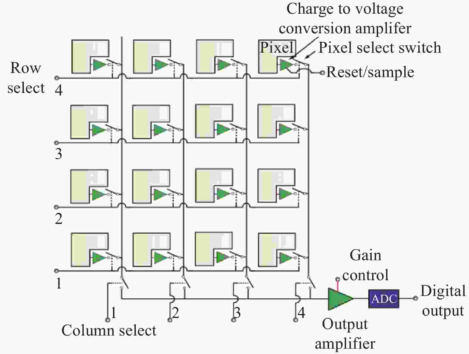
      Figure 3.  Schematic diagram of a CMOS[12]

      CMOS使用电子快门:卷帘快门、全局快门。对于卷帘快门来说,数据读出是从上至下逐行的,这与机械的焦平面快门很像,在拍摄快速移动的物体时会出现斜坡图像、晃动等现象。对于全局快门来说,像素可以在曝光时间积累电荷,曝光结束后电荷被同时传送到存储区域,然后信号从此区域读出。在全局快门下所有像素同时重置、同时传输到存储区域并读出,故相比卷帘门来说,拍摄快速移动物体没有变形。相较全局快门来说,卷帘快门读出结构相对简单,这会产生更少的噪声,实现较低的像素间距,方便研制更高分辨率的探测器[13-14]

      传统CMOS相机由于量子效率低、填充因子低、动态范围小、噪声高、均匀性差等原因,没有被广泛应用于专业天文观测中[15]。近十几年随着技术快速发展,CMOS性能得到了有效提升,2009年,出现了科学级CMOS(scientific CMOS, sCMOS)技术,该技术基于CMOS的架构,通过片上相关多采样技术来降低噪声、调整半导体掺杂比例等提高像元满阱容量、大小增益双路读出合成高动态范围图像技术提高动态范围、二维无缝拼接技术实现大靶面等,克服了CMOS的一些缺点,实现了低噪声、高帧频、高动态范围、高分辨率、大靶面等。sCMOS作为CMOS一种类型,主要应用于科研领域。近些年,越来越多的sCMOS相机被应用于天文光学观测,该类相机能够在快速目标观测、位置测量的巡天观测、偏置导星、太阳观测等天文应用中发挥重要作用[16-17]

    • 对于天文光学观测使用的相机来说,理想的相机要求如下:量子效率高、波长响应范围宽、靶面大、填充因子高、噪声低、读出速度快、电荷转移效率高、像元满阱高、动态范围大、线性度好、稳定性高、暗电流低、功耗低、抗辐射等。但这些却是相互制约的,如读出速度快往往就会导致噪声高、通过制冷降低暗电流的同时也会降低量子效率等,对于用户来说,在使用相机时,需根据观测需求选择合适的相机。

      天文光学观测可以大致分为三个步骤,分别是观测之前的准备工作;使用望远镜进行天文观测;以及观测完毕后对观测数据进行处理与分析。清楚地知道相机各个档位的增益、读出噪声(Readout Noise, RN)、满阱电荷(Full Well Capacity, FWC)、动态范围、线性度可以帮助人们在天文观测之前合理地制定观测策略。在天文观测过程中,根据相机各个档位的性能参数,通过对获得图像进行分析,可以对观测策略进行实时调整,以及对系统隐患、故障进行辅助诊断。在观测完成之后,根据相机的增益、读出噪声、暗电流等参数,可以对观测数据进行精确的数据处理。明确相机的性能参数,在天文观测事前、事中和事后都具有重要的作用和意义。

    • 通过上述分析,以实现相机性能简单、通用检测为目的,以检测结果能够体现天文光学观测对相机性能的基本需求为要求,确定了天文光学相机性能检测项目为增益、读出噪声、满阱电荷、线性度、本底稳定性、像元读出噪声统计、像元响应不均匀性(Photo Response Non-Uniformity, PRNU)、暗电流,选用光子转移曲线法(Photon Transfer Curve, PTC)等。

    • 增益是指输出图像上的一个数字单位(Analog to Digital Units, ADU)代表多少个光生电子,单位为e/ADU。读出噪声是相机在整个信号读出过程中引入的噪声,单位为e RMS。满阱电荷是相机像元在饱和之前可以容纳的最大电荷。一般情况下,当像元亮度接近像元满阱电荷时,电荷就会开始溢出,此时光子转移曲线的线性急剧变差,一般定义非线性度大于3%所对应像元的收集电子数为满阱电荷[18-19]

      增益、读出噪声和满阱电荷可以通过光子转移曲线法来获得,该方法是通过拍摄一系列平场(Flat)来绘制光子转移曲线,通过光子转移曲线来计算相机的系统增益、读出噪声和满阱电荷[19]。使用该方法首先需要有稳定的光源。如果在实验室进行检测可以使用积分球,当相机受光面直径小于积分球光源出口直径一半,感光芯片和积分球出口之间的距离与积分球出口直径的比值在3~5之间时,可在相机受光面上获得均匀性优于99%的照度场[20]。如果不具备实验室环境,可以在稳定房间角落点亮发光二极管,调节电流可以改变亮度,利用房间漫反射形成一个均匀稳定的弱光环境;检查图像是否均匀,如果不均匀需要让相机换一个角度或位置,也可以在相机受光面前添加平整白色打印纸,增加漫反射来均匀光线。

      在黑暗环境下,拍摄两张0 s曝光的本底(Bias):B1B2。调节光源亮度,拍摄一系列曝光时间依次增加的平场,每次拍摄两张F1F2。通常情况下,对于带有机械快门的相机,需考虑快门效应,通过调节光源亮度,使其在5~10 s曝光时间达到图像饱和;对于带电子快门的相机,可以忽略快门效应的影响,3 s以内曝光时间达到图像饱和,提高检测效率。

      光子转移曲线计算方法如公式(1)~(6)所示 1

      式中:Fdif为通过两张相同曝光时间的平场F1F2相减获得的;Bdif为通过两张本底B1B2相减获得的;Gain为增益;RN为读出噪声;σ为标准偏差;Mean为平均值。

      在进行像元满阱测试时,为了避免ADC先达到饱和,需设置待测相机工作的高增益模式,通过拍摄一系列曝光时间依次增加的平场,绘制光子转移曲线,当线性发生急剧变化时,此临界点对应的输出电荷量即为相机满阱值。如果选择低增益模式,有可能ADC先达到饱和,此时测得的像元满阱实际是ADC饱和时所对应的电荷数。

    • 如果相机输出数据与曝光积累的光电子成正比,则器件处于线性工作状态。相机线性度检测可采用稳定强度光源照射,通过改变曝光时间来获取一系列强度依次增加直至饱和的平场,计算每幅图像固定区域所有像元输出的平均值。将得到的多组不同曝光时间与信号强度的数据,绘制曲线后进行线性拟合,得到线性曲线,如公式(7)所示:

      式中:Sout为不同曝光时间下输出的信号强度;Sideal为对应曝光时间在拟合直线上的值,该数值表示理想线性状态下的输出信号强度。通过计算可以获得一系列不同曝光时间的非线性度值,其中最大的即为相机的非线性度[7]

      测试时需要注意,拟合的直线应在相机响应的线性范围内,当信号较弱时,由于陷阱引起的暂留电荷,通常情况下,当电荷小于10~30 e时,已无法正常转移,使有些器件有一个阈值,低于此值,线性度较差;当信号过强时,像元位阱中电荷接近满阱,所积电荷可使驱动钟脉冲发生畸变,造成电荷耦合变坏,开始偏离线性[21]。因此,实际测试时,可以选择满阱容量的20%至满阱位置作为测试区域。也可使用线性度来表示,如公式(8)所示:

    • 暗电流是相机在无光照的情况下产生的电荷,单位是e·pixel-1·s-1[7, 21]

      获取相机暗电流,需要相机在工作温度下,拍摄获取一系列不同曝光时间的暗场图像,每个曝光时间至少拍摄3张图像,用于去除坏像素和宇宙射线的影响。对于深度制冷的相机来说,暗电流通常比较小,需要进行长时间曝光才行,如360 s、720 s、1440 s、1800 s和3600 s等,可根据实际情况和需求合理设定曝光时间。

      将处理后的暗场减去本底,乘以系统增益,就可以获得暗电流和曝光时间的关系曲线,从而计算出暗电流。原则上,每个像元的暗电流都有差别,通常列出的是它们的平均值。

      由于某些相机会有残余电荷,因此,测试前需要尽量长时间地清扫或者使用特殊擦洗模式(如果相机具有该功能),以确保残余电荷不会给暗电流测试带来误差。

    • 用均匀光照射相机时,每个像元输出信号的强度会有差异,这个差异即为相机像元响应的不均匀性,这种差异可以通过平场修正的方法来处理。由于天文相机通常需要深度制冷,暗电流很低,这种情况下可以忽略暗电流带来的影响,用公式(9)表述为:

      式中:PN为像元响应的不均匀性;σA为平场像元ADU的标准偏差;Mean(A)为平场像元ADU的平均值。

      获得像元满阱一半左右的平场,选择中心区域100 pixel×100 pixel,计算像元强度的标准偏差和平均值,得到像元响应的不均匀性,作为相机的响应非均匀性。也可将整幅图按照32 pixel×32 pixel划分成多个区域,计算每个区域的标准偏差及平均值,得到每个区域的像元响应不均匀性,最后将所有区域的像元响应不均匀性平均后作为相机的响应非均匀性[7, 21-23]

    • 根据天文观测对相机的需求,列出了天文观测所关注的天文光学相机的性能指标,并给出了对应的测试方法。基于现有的实验室设备及条件,选用sCMOS和CCD相机进行性能检测,完成检测实验。

      检测方法验证实验使用的两款相机分别是Andor Marana sCMOS和Andor iKon-L 936 CCD (如图4所示),两款都是使用科学级背照式感光芯片而研制的科学级相机,均已应用在天文光学观测上。

      Figure 4.  The Andor Marana sCMOS camera (a) and the Andor iKon-L 936 CCD camera (b) (https://andor.oxinst.com/)

      在光学暗室对两款天文在用相机开展了一系列的测试,测试包括读出增益、噪声、满阱电荷、线性度、暗电流、满阱电荷、动态范围、响应不均匀性、本底噪声分布、本底稳定性等。

    • 在暗室光学平台上搭建测试系统,如图5所示,从左到右依次为:待测相机、暗箱、积分球、稳定光源。使用Thorlabs 365 nm M365L2作为光源,分别使用相机拍摄黑暗环境下的0 s曝光的本底两帧:B1B2;使用稳定光源积分球拍摄曝光时间依次增加的平场,每次拍摄各两帧F1F2;按照2.2.1条光子转移曲线的方法获得相机的增益、读出噪声和满阱电荷。

      Figure 5.  Set up of test platform in an optical dark room

      选择图像中心区域[600:1400, 600:1400],sCM-OS相机12-bit档位下绘制的光子转移曲线,如图6所示。

      Figure 6.  PTC of Marana sCMOS camera in the 12-bit setting

      从PTC可以看出,在ADU为3700左右,曲线开始急剧下落,可以确定满阱位置;增益、读出噪声、满阱电荷分别约为0.55 e/ADU、3.61 e、2044 e

      在PTC中,拟合曲线采用直线Y=aX+b进行拟合,利用公式(7)计算每个点的非线性度,对PTC的非线性进行分析。由于sCMOS或者CCD系统的线性在输入光量极低和接近满阱的高端都会迅速变坏,通常选择ADC位深的20%至满阱位置进行分析计算。如图6所示,sCMOS 12-bit档位的PTC非线性约为1.42%。

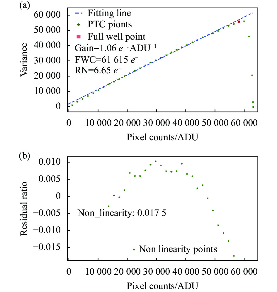
      按上述方法对iKon-L CCD 1 MHz 4×档位进行了测试,得到的PTC如图7所示。从图中可以看出,iKon-L CCD 1 MHz 4×档位下,当ADU为58000左右,曲线开始急剧下落,可以确定该档位下的满阱位置;该档位的增益、读出噪声、满阱电荷分别约为1.06 e·ADU−1、6.65 e、61600 e;计算该档位下的非线性度,选择ADC位深的20%至满阱位置进行,约为1.71%。

      Figure 7.  PTC of iKon-L 936 CCD camera in the 1 MHz 4× setting

    • 如果相机输出数据和输入信号成正比,则设备工作处于线性状态。相机具有良好的线性对于天文观测很重要,只有线性系统才能精确比较不同大小的输入信号。

      在稳定光源下,曝光时间依次增加,获得一系列平场即可评估探测器的线性度。3.1节中已经获得了这些平场,选择中心区域[600:1400, 600:1400],对该区域的输出信号求均值,与曝光时间结合可以得出相机的线性度曲线。

      sCMOS相机12-bit档位下绘制的线性度曲线如图8所示,与3.1节对应,ADC位深的20%至满阱位置进行计算,线性度约为99.71%。图中标注位置是PTC图像中的满阱位置,虽然从线性曲线上可以看出还远不到线性曲线的拐点,但是在PTC曲线中已经超过了线性范围,故在实际天文观测中,需控制曝光时间,将观测目标ADU控制在3700以下。

      Figure 8.  Linearity curve of Marana sCMOS camera in the 12-bit setting

      对于iKon-L CCD,采用了上述同样的方法,使用3.1节中已经获得的平场数据,选择中心区域[600:1400, 600:1400],对该区域的输出信号求均值,考虑曝光时间可以得出相机的线性度曲线。其中CCD 1 MHz 2×档位下的线性曲线如图9所示,同样选择ADC位深的20%至满阱位置进行计算,线性度约为99.95%。在实际观测中,如使用该档位需将观测目标ADU控制在58000以内。

      Figure 9.  Linearity curve of iKon-L 936 CCD camera in the 1 MHz 4× setting

    • 本底的稳定性对天文观测来说很重要,如果在观测过程中本底不稳定,就不利于高精度的观测。为了对这两款相机的本底稳定性进行测试,每2 min拍摄一张本底,分别获取了至少200张不同档位的本底图像,通过对中心区域[600:1400, 600:1400]求均值进行统计分析,即可获得至少400 min内的本底变化情况。

      按上述统计方法对sCMOS 12-bit和CCD 1 MHz 4×档位的本底进行了分析,结果如图10所示。sCMOS的12-bit本底ADU在207.4左右,连续采集400 min,起伏1 ADU左右,本底稳定性为99.89%;CCD 1 MHz 4×档位下的本底ADU在2216左右,连续采集600 min,起伏2 ADU左右,本底稳定性为99.96%。

      Figure 10.  Time series samples of bias counts of the sCMOS camera in the 12-bit (a) and the CCD camera in the 1 MHz 4× (b) settings

      通过测试表明,两款相机两个档位的本底都比较稳定。

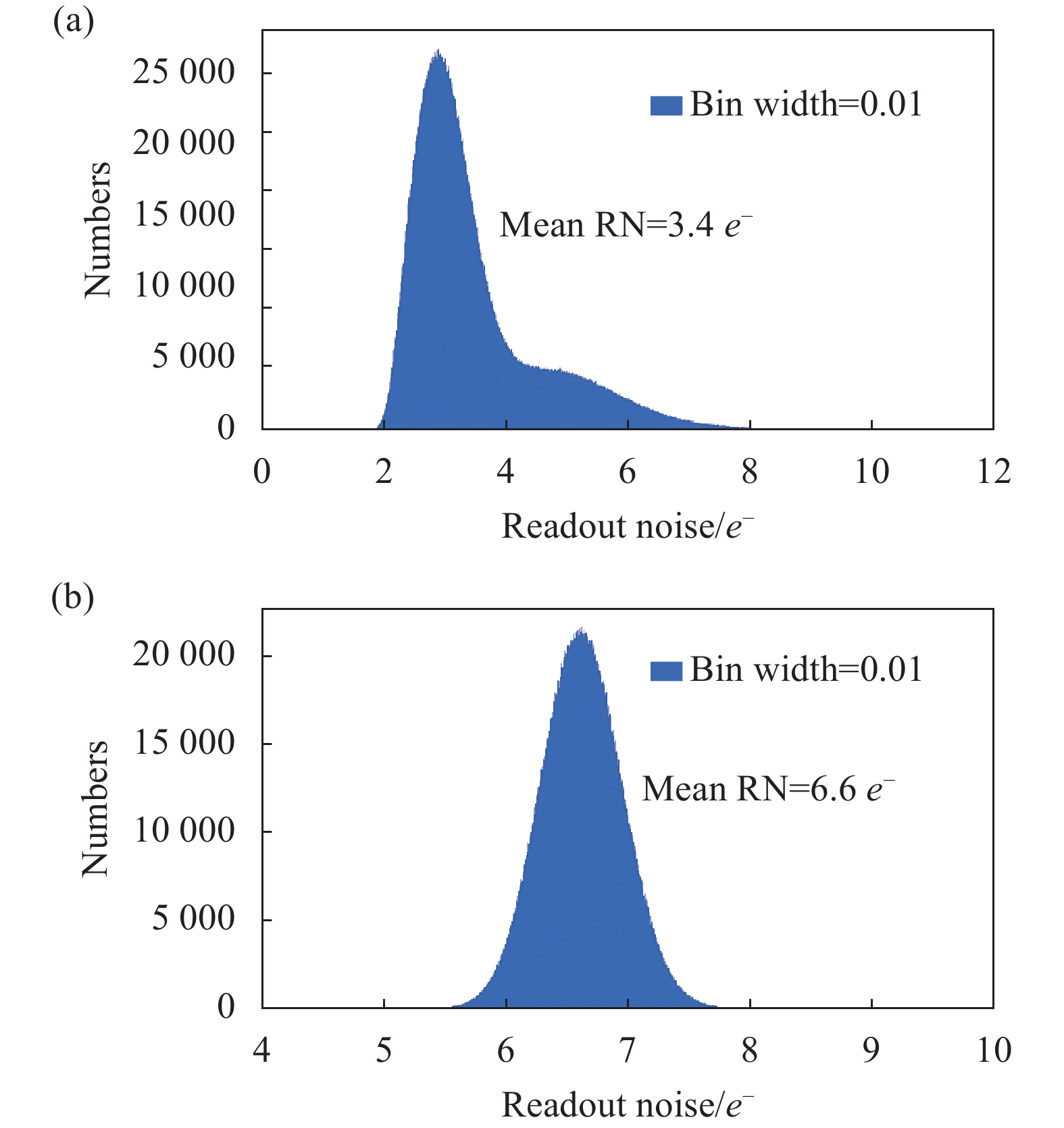
    • 为了分析图像像元的读出噪声情况,使用3.3节已采集的200张本底,计算对应每一个像元ADU的标准偏差;标准偏差乘以增益即为该像元的读出噪声。对图像全部像元进行读出噪声的统计,均值即为读出噪声。

      按上述统计方法对sCMOS的12-bit和CCD 1 MHz 4×档位的本底进行分析,结果如图11所示。CCD的1 MHz 4×档位像元读出噪声的统计呈高斯分布,读出噪声为6.62 e;sCMOS的12-bit档位像元读出噪声的统计中呈高斯轮廓,高斯轮廓右下角有延伸,延伸的部分即为像元噪声比较高的统计,计算两个档位读出噪声为3.44 e。与3.1节通过PTC方法计算读出噪声相比,两者计算的档位读出噪声基本一致。

      Figure 11.  Histograms of number density of pixel RN measured with the sCMOS camera in the 12-bit (a) and the iKon-L CCD camera in the 1 MHz 4× (b) settings

    • 对于密集星场、巡天等天文观测,动态范围大的相机可以记录更多的信息。根据上述获得的数据,可以计算出相机各个档位的动态范围,便于观测前根据相机性能制定合适的观测计划。相机动态范围可以通过满阱电荷除以读出噪声来进行估算。

      根据3.1节测得的结果,sCMOS的12-bit和CCD 1 MHz 4×档位的动态范围分别为:568:1,9159:1。通过计算,可以对比相机不同档位的动态范围,但是该数值并不能直观地体现一幅天文图像在线性范围内最亮目标和最暗目标的星等差值,可以通过理论计算进行分析。单个目标星信噪比(signal-to-noise ratio, SNR)如公式(10)所示:

      式中:R*为相机接收到的目标源信号;Rsky为相机接收到的天空背景信号;t为相机的曝光时间;npix为测光时目标所占的像素数;D为相机的暗电流;Gain为相机的增益;RN为相机的读出噪声。

      式中:ΔM为星等差;M1为目标1的星等;M2为目标2的星等;F1为目标1的流量;F2为目标2的流量。

      假设若要分辨出最暗目标,该目标信噪比要大于等于3,不考虑天光背景和暗电流的影响,假设单个目标所占的像元为3×3,根据3.1节测试结果见表1;可以求出该情况下,sCMOS 12-bit和CCD 1 MHz 4×档位的图像中最亮目标(达到满阱)和最暗目标(信噪比为3)的星等差分别为4.35和7.44星等。

      CameraFWC/
      e
      RN/
      e
      Gain/
      e·ADU−1
      Flux/e
      (SNR =3)
      sCMOS2 0443.610.5537.3
      CCD 61 6006.651.0664.3

      Table 1.  Performance parameters of the cameras setting when the SNR of a single target is 3

    • 使用3.1节中满阱约50%的平场,选择中心区域100 pixel×100 pixel,来评估相机像元响应不均匀性。

      通过计算,sCMOS 12-bit和CCD 1 MHz 4×档位的像元响应不均匀性分别为3.49%和1.78%。

      为了提高天文观测的精度,可以使用张涛等提出的自适应多点非均匀性校正方法来改善sCMOS像元不均匀性大的问题[24]

    • 暗电流是探测器在不感光的情况下,自身产生的热生电荷。暗电流存在起伏,对于天文观测来说是噪声;同时暗电流占用了像元的阱深容量,导致存放信号变小,所以对于天文观测来说,减少暗电流很重要。天文在用相机通常通过降低探测器的制冷温度来降低暗电流。

      实测sCMOS和CCD分别在室温20 ℃左右环境下,制冷温度分别可以达到−45 ℃和−80 ℃,拍摄多幅本底,然后使用IRAF进行合并;拍摄不同曝光时间的暗场图像,每个曝光时间拍摄三幅。暗电流图像减去合并的本底,然后使用IRAF对相同曝光的暗电流图像进行合并去除宇宙线的影响。

      在MaxIm DL软件中打开曝光时间依次增加的暗电流图像,将sCMOS 12-bit和CCD 1 MHz 4×档位暗电流图像按照相同的对比度进行线性显示,暗电流变化情况如图12图13所示。

      Figure 12.  Changes in dark images obtained with the sCMOS camera in the 12-bit setting

      Figure 13.  Changes in dark images obtained with the CCD camera in 1 MHz 4× the setting

      实测sCMOS曝光时间最长可以设置为600 s,CCD没有曝光时间限制。从暗电流图像可以看出,该sCMOS芯片在上部有几处发光点,发出的辉光随着曝光时间的增加而增加,曝光时间过长辉光会影响到周围的像元;而CCD芯片在长时间积分的情况下并没有任何辉光的情况发生。对于sCMOS相机,由于受辉光的影响,整个靶面中呈现出明显不均匀的情况,曝光时间在10 s之内12-bit档位的暗电流图像变化不是很大。对于CCD相机来说,随着曝光时间的增加,暗电流在整个靶面增加,未出现明显不均匀的现象。

      对于sCMOS,为了分析暗电流和辉光的特性,发光点位置从近到远分别选择[1000:1050, 200:250],[1000:1050, 500:550],[1000:1050, 1000:1050],[1000:1050, 1700:1750] 共四个区域进行统计分析,ADU乘以增益可以得到暗电流电子数,除以曝光时间可以得到每秒每像元暗电流的电子数。如图14所示,虽然有辉光出现,但是暗电流和辉光带来的影响是线性增加的,所以如需长曝光观测,可以通过做暗场修正来处理暗电流和辉光带来的影响。但是,辉光影响到像元的满阱、动态范围、信噪比等无法修正。通过计算可得sCMOS 12-bit档位的四个区域暗电流和辉光为1.04 、0.68、0.38、0.24 e·pixel−1·s−1。如果sCMOS未受辉光的影响,假设远离发光点的位置处为芯片本身的暗电流,故12-bit档位下暗电流约为0.24 e·pixel−1·s−1

      Figure 14.  Dark current obtained with the sCMOS camera in the 12-bit (a) and CCD camera in the 1 MHz 4× setting (b)

      CCD比sCMOS的暗电流要低很多,选择中心区域[800:1200, 800:1200]进行统计分析,曝光10 min以下基本上很难测试出暗电流,需要更长时间的积分才行,依次获得不同曝光时间的暗电流图像,经上述方法进行分析后,CCD 1 MHz 4×档位下暗电流约为0.014 e·pixel−1·s−1

    • 为了对第2节提出的检测项目、检测方法、检测实验和数据处理方法进行验证,选用Marana sCMOS和iKon-L 936 CCD,在实验室开展了性能检测实验,得到了两款相机的性能参数,如表2所示。

      CameraSettingGain/
      e·ADU−1
      RN/
      e
      FWC/
      e
      FWC point/
      ADU
      LinearityStability of biasDRPRNUDark current/
      e·pixel−1·s−1
      Marana sCMOS12-bit0.553.612 044370099.71%99.89%568:1
      4.35 mag
      3.49%0.24
      iKon-L 936 CCD1 MHz 4×1.066.65616005800099.95%99.96%9159:1
      7.44 mag
      1.78%0.014

      Table 2.  Performance test results of the sCMOS and CCD

      通过检测结果可以明确相机档位的具体性能参数,对于天文观测方案的制定、观测策略的调整、数据处理、故障诊断等都具有重要作用;可实现对相同相机不同档位、或者不同相机档位之间的对比,为选择适合需求的档位或者相机进行观测提供了依据;定期对相机进行检查可以建立该相机全生命周期的数据库,可以对相机进行健康状态管理、故障诊断等。

    • 相机是光学望远镜观测系统的重要组成部分,明确相机性能参数,对于天文观测方案的制定、观测策略的调整、数据处理、故障诊断等都具有重要作用。为了提高天文光学观测的精度和效能,开展了天文光学相机性能检测的技术研究。通过介绍天文光学观测使用的CCD和sCMOS相机,并对天文光学观测对相机的性能需求进行分析,给出了相机性能检测项目、检测方法、检测实验和数据处理方法,检测项目包括增益、读出噪声、满阱电荷、线性度、本底稳定性、像元响应不均匀性、暗电流等。

      根据制定的检测项目、检测方法、检测实验和数据处理方法,搭建检测实验,对比测试了Andor Marana sCMOS和Andor iKon-L 936 CCD相机。测试结果显示,Marana sCMOS 12-bit档位相较iKon-L 936 CCD 1 MHz 4×档位,读出噪声低约1倍,暗电流高17倍,动态范围约低3星等,像元响应不均匀性约高1倍;两款相机都具有较高的线性度和本底稳定性;该sCMOS具有辉光,不适合长时间的曝光观测。该方法可检测适用于天文光学观测的相机性能参数,并使用天文常用单位进行表述,便于开展天文实测工作。

      文中仅对相机某一个档位进行了性能检测,如使用该检测方法对相机所有档位进行测试,能够获得相机全档位的性能参数,对于天文观测方案的制定、观测策略的调整、数据处理、故障诊断等都具有重要作用。该方法可以实现对相同相机不同档位、或者不同相机档位之间的对比,帮助用户选择适合其观测需求的相机档位或者相机进行天文观测,以便获得更好的观测数据。可以定期对相机进行性能检测,建立相机全生命周期性能参数的数据库,便于相机健康状态管理和观测系统故障诊断。

Reference (24)

Catalog

    /

    DownLoad:  Full-Size Img  PowerPoint
    Return
    Return