


 下载:
下载:


-
超材料指由亚波长共振单元按特定方式排列而成的、可以实现奇异物理特性的人工复合材料。超材料由于其非凡的材料特性以及由此产生的对宽谱(从可见光到太赫兹波段)电磁波的通用显著操纵能力而引起了人们的广泛关注[1-2]。超表面是超材料的二维等价物[3-7],光学超表面利用亚波长结构与光的相互作用来调节振幅、相位和偏振等特性,具有超轻、超薄、易于集成的优点,易于制备平面化集成化的光学设备与器件,如光束偏转器[8]、涡旋相位板[9-10]、全息图[11]、超透镜[12-14]。透镜是在光学领域中应用十分广泛的核心光学元件。基于超表面的超透镜是一种由致密平面内的非均匀光学天线阵列组成的透镜。相对于传统透镜结构,它可以改善笨重且巨大的光学系统。由于其对传输和反射电磁波的相位具有前所未有的控制能力,已成为发展小型化光学透镜的通用手段。基于不连续相位原理,超表面可以对光实现局部操纵,以理想的方式传递突变相移,打破了对沿光路连续相位累积的依赖。太赫兹光谱存在着许多优越的特性从而使太赫兹波段受到人们广泛的关注与应用,并且其拥有着非常广阔的应用前景。因为太赫兹的脉冲在皮秒数量级,其在时域频谱的信噪比很高,所以太赫兹波是成像系统中的一个最佳选择波源[15]。
近年来,研究者已经从理论或实验上实现了各式各样的单焦点超透镜[16],然而对双焦点或多焦点超透镜的研究较少。多焦点超透镜将一束入射光纵向或横向聚焦到不同的位置,因此在光通信、多成像系统、光学层析成像技术、光学数据存储等方面有着重要的应用。2015年,Chen Xianzhong等[17]设计了由三个子透镜组成的三焦点超透镜,其中每个子透镜对应一个焦点。2018年,Wang Wei等[18]通过交替摆放两个子透镜单元,设计了偏振依赖的横向或者纵向分开的双焦点超透镜。2020年,Zhou Tao等[19]通过多路复用多个子透镜,设计了自旋依赖的多焦点超透镜。虽然已经实现了一些双焦点或多焦点超透镜[17-20],但它们大部分都是将多个单焦点超透镜基于复用的形式组合成一个多焦点超透镜,导致不可避免的串扰和较低的聚焦效率,而且不便于控制不同焦点之间的相对强度。如果想调制不同的聚焦强度比,设计者不得不重新设计超透镜,这是非常耗时且不便于实际应用的。鉴于已有的双焦点超透镜存在上述问题,笔者将超透镜的每个晶胞单位的几何相位和传播相位同时调控,通过改变入射光束的偏振态来灵活地调制超透镜的两个焦点之间的相对强度。另外,透镜的数值孔径(NA)决定了其聚焦分辨率和聚光能力,通过巧妙地参数设计使该透镜具有很高的数值孔径和聚焦效率。所提出的强度可调的高数值孔径以及高效率的横向离轴双焦点超透镜在光学领域将具有很大的潜在应用价值。此外,还研究了斜入射和多波段下的聚焦效果及其离轴特性,为集成光子器件的设计和制造提供了新的途径。
-
超透镜技术通常涉及两种相位:传输相位和几何相位。传输相位是通过改变单元结构的几何参数,利用等效折射率来实现对相位的调控。因此,通过控制单元结构的几何尺寸,可以得到覆盖0~2π范围的传输相位。几何相位也称为Pancharatnam-Berry (PB)相位,通过改变单元结构的方位角来实现对圆偏振散射光相位的调控。因此,通过控制单元结构的方位角,可以得到覆盖0~2π范围的几何相位。可以实现聚焦功能的超透镜须拥有传统球面透镜的功能,从超透镜发出的电磁波在焦平面处要发生相长干涉。根据等光程原理,单焦点超透镜中任意一点的相位可表示为:
$$ \varphi (x,y) = {{2\pi } \mathord{\left/ {\vphantom {{2\pi } \lambda }} \right. } \lambda }\left( {\sqrt {{x^2} + {y^2} + {f^2}} - f} \right) $$ (1) 式中:
$\lambda $ 为入射波长;x和y为超透镜平面坐标;$f$ 为超透镜的焦距。只要选定了$\lambda $ 和$f$ ,任意位置的结构单元所满足的相位也随之确定。为了设计一个对于圆偏振(CP)光有两个横向分开焦点的二维聚焦超透镜。左旋圆偏振(LCP)光入射时,透镜各点的相位可表示为:$$ {\varphi _{RL}} = {{2\pi } \mathord{\left/ {\vphantom {{2\pi } \lambda }} \right. } \lambda }\left[ {\sqrt {{{\left( {x - {x_0}} \right)}^2} + {f^2}} - f} \right] $$ (2) 右旋圆偏振(RCP)光入射时,透镜各点的相位可表示为:
$$ {\varphi _{LR}} = {{2\pi } \mathord{\left/ {\vphantom {{2\pi } \lambda }} \right. } \lambda }\left[ {\sqrt {{{\left( {x + {x_0}} \right)}^2} + {f^2}} - f} \right] $$ (3) 式中:
$x{}_0$ 为焦点偏离中心位置的距离。对于半波片来说,透射光只含有交叉偏振光,基于几何相位和传输相位可以得到
${\varphi _{RL/LR}} = {\phi _{xx}} \pm 2\theta $ ,其中${\phi _{xx}}$ 为x线偏振(XLP)光入射时x线偏振透射光所对应的相位。也就是说,通过为单元结构选择合适的几何尺寸和旋转角度,可以分别得到其在LCP和RCP光入射时所对应的相位。进一步来说,如果单元结构同时工作于LCP和RCP入射光,那么XLP光所对应的传输相位和旋转角度满足的方程可分别写为:$$ {\phi _{xx}} = \frac{1}{2}\left[ {\left( {{\varphi _{RL}} - 2{n_1}\pi } \right) + \left( {{\varphi _{LR}} - 2{n_2}\pi } \right)} \right] $$ (4) $$ \theta = \frac{1}{4}\left[ {\left( {{\varphi _{RL}} - 2{n_1}\pi } \right) - \left( {{\varphi _{LR}} - 2{n_2}\pi } \right)} \right] $$ (5) 式中:
${n_1}$ 和${n_2}$ 为整数。因此,通过选择具有合适的几何尺寸和旋转角的单元结构,可以实现任意的相位分布,从而可以设计具有任意横向距离为$2{x_0}$ 的双焦点超透镜。 -
设计了对于LCP和RCP入射光都具高透射效率和良好会聚功能的超透镜,聚焦原理图如图1(a)所示,每个单元结构对于LCP和RCP光都具有会聚作用。选择入射波长为300 μm(频率为1.0 THz),经过一系列的调研及实验仿真模拟,最终选择了硅微砖和聚4-甲基戊烯-1(TPX)基底作为基本结构单元,具体如图1(b)~(d)所示。晶体硅在该波段具有高折射率(n=3.41)且没有吸收损耗。TPX是一种最轻的耐热透明塑料,它在1.0 THz具有非常小的吸收损耗,其折射率为1.47,介于硅和空气的有效折射率之间,可以实现阻抗匹配和高的透射效率。为了确保高效率,通过时域有限差分法(FDTD)进行仿真计算,优化后的参数为:单位晶胞尺寸P=150 μm,硅微砖高度H=195 μm。然后通过对臂长L和臂宽W进行仿真扫描,得到一系列透射率高达90%且相位覆盖0~2π的硅微砖。令焦距
$f$ =1200 μm,${x_0}$ =6P=900 μm,为了实现公式(2)、(3)所描述的双焦点超透镜的相位剖面,任意位置的硅微砖必须拥有符合公式(4)、(5)所对应的传输相位和旋转角度。这样就可以得到每个硅微砖具体的几何参数,其同时满足LCP和RCP光聚焦的相位分布。
图 1 (a) 双焦点超透镜聚焦示意图;(b)~(c) 具有高度H、长度L、宽度W的硅微砖的侧视图和俯视图,其中单位晶胞尺寸为P;(d)具有旋转角度为θ的硅微砖的俯视图;(e) 构建的双焦点超透镜的俯视图
Figure 1. (a) Schematic of focusing of the bifocal metalens; (b)-(c) Side and top views of silicon microbricks with height H, length L and width W, and the unit cell size is P; (d) Top view of the silicon microbrick with rotation angle θ; (e) Top view of the constructed bifocal metalens
-
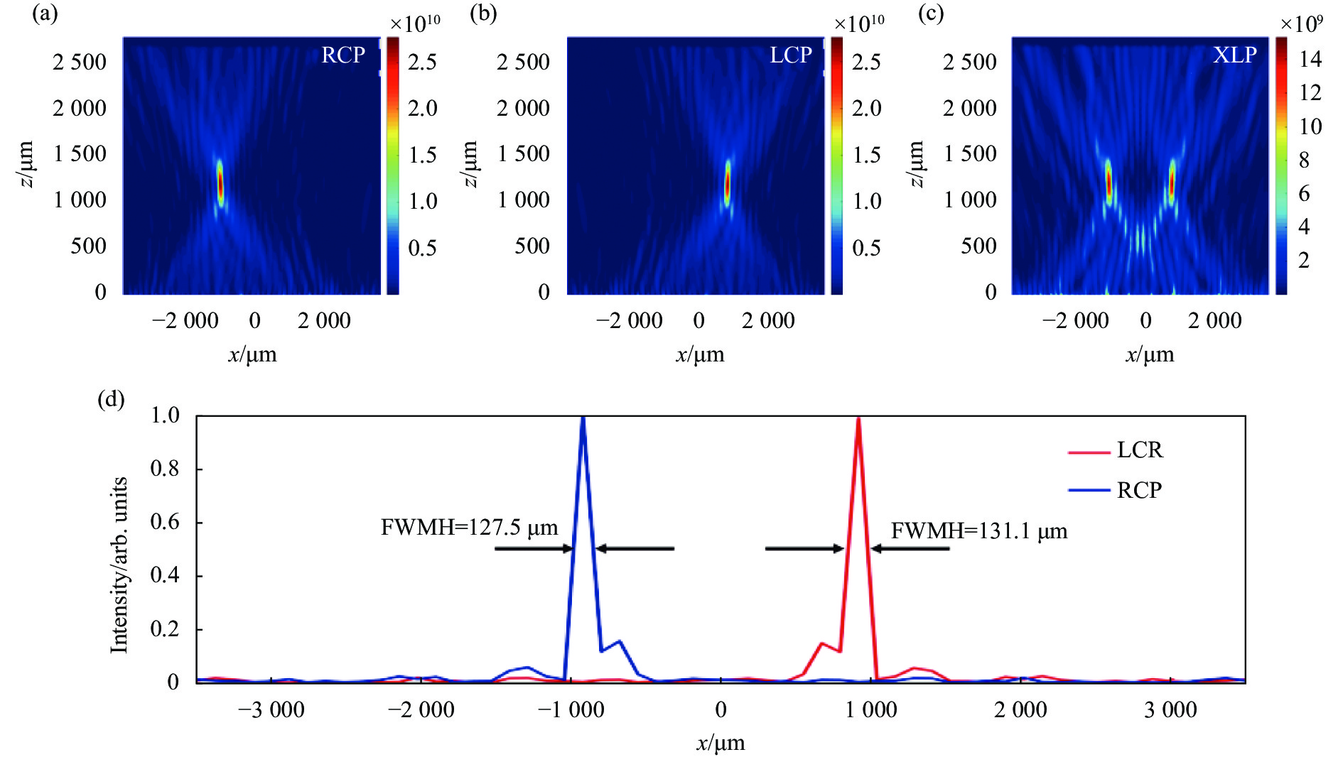
选取了49个硅微砖组成了一个沿x轴方向的超透镜,如图1(e)所示,由于设置的焦距为1200 μm,其数值孔径高达0.95。基于FDTD数值仿真时,y方向设置周期边界条件,z方向设置完美匹配层边界条件。如图2(a)所示,当RCP光入射时,透射的LCP光被聚焦在(−900 μm,1200 μm)处。如图2(b)所示,当LCP光入射时,透射的RCP光被聚焦在(900 μm,1200 μm)处。可以发现,超透镜对于LCP和RCP光都可以实现很好的单焦点聚焦,且聚焦的位置和预设的位置符合得非常好。半高全宽(FWHM)是描述焦点光斑大小的常用参数。当RCP光入射时,如图2(d)中蓝线所示,焦点的FWHM为127.5 μm。当LCP光入射时,如图2(d)中红线所示,焦点的FWHM为131.1 μm。在较大的数值孔径下获得了较小的光斑尺寸,这意味着超透镜对于LCP和RCP光同时具有优秀的聚焦效果。由透镜的衍射极限公式
$ d = {{0.5\lambda } \mathord{\left/ {\vphantom {{0.5\lambda } {NA}}} \right. } {NA}} $ , 可求得该超透镜的理论分辨极限为158 μm,可以看出,LCP和RCP光入射下的半高宽均小于该值,因此所设计的超透镜打破了衍射极限。更为重要的是,在RCP和LCP入射光下,该超透镜的聚焦效率均为65%,远远高于等离子体超透镜的聚焦效率,也远远高于基于多路复用的介电质超透镜的聚焦效率,具有重要的实际应用价值。由于XLP光可以被分解成具有相同振幅的LCP和RCP分量,那么当XLP光入射时将会有两个强度几乎相等的焦点。当XLP光入射时,图2(c)显示了其聚焦场的强度分布,与理论分析一致,该超透镜产生了间距相距1800 μm的聚焦强度几乎一致的两个焦点。值得注意的是,两个焦点具有不同的偏振态,左位置焦点的偏振态为左旋圆偏振,右位置焦点的偏振态为右旋圆偏振。
图 2 双焦点超透镜在RCP (a)、LCP (b)和XLP (c)光入射下的聚焦场的强度分布;(d) RCP(蓝线)和LCP(红线)光分别入射产生通过焦点的沿着x轴的强度分布曲线
Figure 2. Intensity distribution of the bifocal metalens under the RCP (a), LCP (b) and XLP (c) incidence light, respectively; (d) Intensity distribution curve along the x-axis through the focal point under the RCP (blue line) and LCP (red line) incidence light, respectively
-
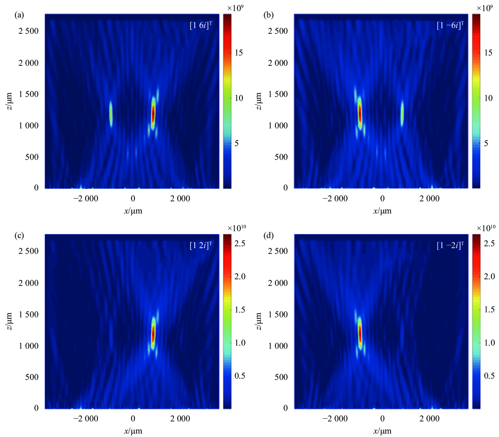
由于椭圆偏振光束可以分解为两个正交圆偏振态:左旋圆偏振态和右旋圆偏振态,因此对于所设计的双焦点超透镜,当椭圆偏振光入射时,透射场中依然会出现两个偏振态分别为LCP和RCP的两个焦点,其中左侧焦点的偏振态为LCP,其对应椭圆偏振入射光的RCP分量;右侧焦点的偏振态为RCP,其对应椭圆偏振入射光的LCP分量。当改变椭圆偏振入射光的椭圆度时,透射的LCP和RCP分量的比例也会变化,导致左右位置的两个焦点相对强度的改变。也就是说,通过改变椭圆偏振光的长短轴的比例,可以灵活地调制左右位置焦点的相对强度。 仿真计算了四种椭圆偏振入射光所对应的聚焦现象,如图3(a)~(d)所示。当入射光为
$ {E_{in}} = \left[ {\begin{array}{*{20}{c}} 1 \\ {6i} \end{array}} \right] $ 时,如图3(a)所示,左位置焦点的强度变弱,右位置焦点的强度变强。当入射光为$ {E_{in}} = \left[ {\begin{array}{*{20}{c}} 1 \\ { - 6i} \end{array}} \right] $ 时,与前一个情况正好相反,如图3(b)所示,左位置焦点的强度变强,右位置焦点强度变弱。当入射光为$ {E_{in}} = \left[ {\begin{array}{*{20}{c}} 1 \\ {2i} \end{array}} \right] $ 时,如图3(c)所示,左位置焦点的强度将变得更弱,右位置焦点的强度则会变得更强;当入射光为$ {E_{in}} = \left[ {\begin{array}{*{20}{c}} 1 \\ { - 2i} \end{array}} \right] $ 时,相较于图3(b),图3(d)显示左位置焦点的强度将变得更强,右位置焦点的强度则会变得更弱。由图2(a)~(c)可知,当入射光为$ {E_{in}} = \left[ {\begin{array}{*{20}{c}} 1 \\ i \end{array}} \right] $ 时,只出现右位置焦点;当入射光为$ {E_{in}} = \left[ {\begin{array}{*{20}{c}} 1 \\ { - i} \end{array}} \right] $ 时,只出现左位置焦点;当入射光为$ {E_{in}} = \left[ {\begin{array}{*{20}{c}} 1 \\ 0 \end{array}} \right] $ 时,左右位置焦点强度几乎相同。综上所述,通过改变入射光束的偏振态,可以灵活地调节两焦点之间的相对强度。在实际应用中,通过旋转放置超透镜前的四分之一波片可以调制左右位置两个焦点的相对强度,这种强度可调的超透镜可以方便且高效地应用在光学层析成像技术、光学数据存储等领域。
图 3 当入射光分别为
$ {[ {\begin{array}{*{20}{c}} 1\;\;{6i} \end{array}} ]^{\text{T}}} $ (a),$ {[ {\begin{array}{*{20}{c}} 1\;\;{ - 6i} \end{array}} ]^{\text{T}}} $ (b),$ {[ {\begin{array}{*{20}{c}} 1\;\;{2i} \end{array}} ]^{\text{T}}} $ (c) 和$ {[ {\begin{array}{*{20}{c}} 1\;\;{ - 2i} \end{array}} ]^{\text{T}}} $ (d) 时,聚焦场的强度分布Figure 3. Intensity distribution of the focusing field when the incident light is
$ {[ {\begin{array}{*{20}{c}} 1\;\;{6i} \end{array}} ]^{\text{T}}} $ (a),$ {[ {\begin{array}{*{20}{c}} 1\;\;{ - 6i} \end{array}} ]^{\text{T}}} $ (b),$ {[ {\begin{array}{*{20}{c}} 1\;\;{2i} \end{array}} ]^{\text{T}}} $ (c) and$ {[ {\begin{array}{*{20}{c}} 1\;\;{ - 2i} \end{array}} ]^{\text{T}}} $ (d), respectively -
平面超透镜虽然可以纠正球面像差,但是对于斜入射的光束仍然具有离轴像差。所设计的离轴透镜在一定角度内可以很好地在理想的空间位置实现成像。为了进一步证明该设计的广角聚焦特性,研究了双焦点超透镜在RCP光和LCP光以不同的角度(10°、20°)入射下的聚焦行为。定义焦距的离轴角为
$\alpha = {\rm arctan}\left( {{{{x_0}} \mathord{\left/ {\vphantom {{{x_0}} f}} \right. } f}} \right)$ ,离轴角向左为负,向右为正。RCP和LCP光以10°的角度斜入射时,如图4(a)和(b)所示,离轴角分别为−25°和42°;RCP光和LCP光以20°的角度斜入射时,如图4(c)和(d)所示,离轴角分别为−13°和48°。可见随着斜入射角度的增大,离轴角也会增大,与实际情况相符。从图4(a)~(d)中还可以看到,当入射角度为10°和20°时,RCP光和LCP光的透射电场分布都为向右凸的抛物面,且此时超透镜仍然维持了很好的聚焦能力,这意味着所设计的双焦点超透镜可以实现一定范围内的广角聚焦。
图 4 当RCP光以10°(a)和20°(c)分别入射时聚焦场的强度分布;当LCP光以10°(b)和20°(d)分别入射时聚焦场的强度分布
Figure 4. Intensity distribution of the focusing field when the RCP light incidence with the angle of 10° (a) and 20° (c), respectively; Intensity distribution of the focusing field when the LCP light incidence with the angle of 10° (b) and 20° (d), respectively
-
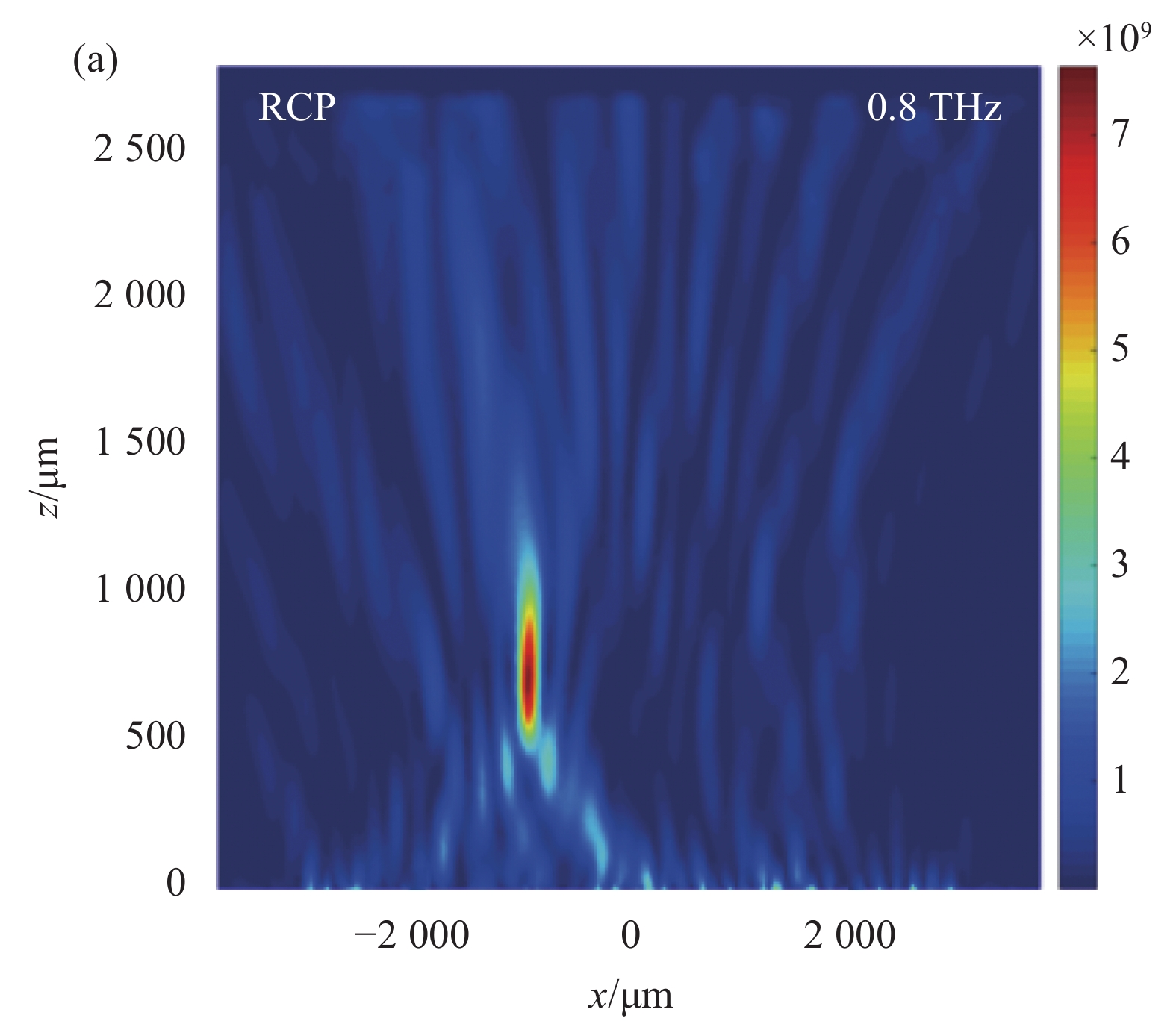
此外,还研究了双焦点超透镜在不同波段下的RCP光和LCP光垂直入射所产生的聚焦行为,如图5(a)~(d)所示,双焦点超透镜在0.8~1.2 THz的较宽频率范围内仍然有很好的聚焦效果。当用频率为0.8 THz的 RCP光和LCP光垂直入射时,焦点向下偏移到750 μm,此时的离轴角分别为−50°和50°;而当用频率1.2 THz的 RCP光和LCP光垂直入射时,焦点向上偏移至1700 μm,此时的离轴角分别为−28°和28°。因此,随着频率的减小,透镜的焦距随之变小,离轴角的绝对值随之变大;随着频率的增大,透镜的焦距随之变大,离轴角的绝对值则随之变小。

图 5 频率为0.8 THz的 RCP(a)和LCP(b)光垂直入射时聚焦场的强度分布;频率为1.2 THz的RCP(c)和LCP(d)光垂直入射时聚焦场的强度分布
Figure 5. Intensity distribution of the focusing field when the RCP (a) and LCP (b) light incidence with the frequency of 0.8 THz; Intensity distribution of the focusing field when the RCP (c) and LCP (d) light incidence with the frequency of 1.2 THz

-
文中设计了一种强度可调的高数值孔径的横向双焦点超透镜。根据入射光的偏振态,超透镜可以沿横向将入射光聚焦到一个或者两个焦点。由于超透镜的设计是基于几何相位和传输相位两种相位调控模式,超透镜的每个晶胞单元同时对LCP和RCP光同时起作用,其聚焦效率对于LCP和RCP光都达到了65%。当LCP或RCP光入射时,超透镜只有一个焦点;当椭圆偏振光或者线偏振光入射时,超透镜有两个焦点。更重要的是,不需要设计新的超透镜,只通过改变椭圆偏振光的偏振态就可以调制两个焦点的相对强度,在实际应用中非常高效和方便。最后仿真验证了该透镜的广角特性以及宽带特性。所设计的双焦点超透镜在多功能超表面、多成像系统和集成设备方面具有十分重要的应用价值及广阔的发展前景。
High numerical aperture bifocal metalens with regulatory focusing intensity
-
摘要: 基于超表面对光波的振幅、相位和偏振进行调控来实现聚焦与成像的超透镜受到广泛关注。设计了一种聚焦强度可调的高数值孔径的双焦点超透镜,并进行了理论分析和仿真验证。仿真结果表明,该超透镜能有效地将圆偏振入射光聚焦到半高宽为0.44λ的光斑上,对应的数值孔径高达0.95。此外,通过改变入射光的偏振态,可以灵活地调制两个焦点的相对强度,而不同于以往的双焦点超透镜需要对光强进行重新组合。更重要的是,当圆偏振光入射时,它的聚焦效率可达65%,可适用在0.8~1.2 THz的较宽频率范围和0°~20°的入射角内,同时该工作为多焦点超透镜的设计提供了重要思路,也将在多成像系统、光学层析成像技术等许多领域具有较高的应用价值。Abstract: The metalenses with focusing and imaging based on metasurfaces, which can manipulate the amplitude, phase, and polarization of light waves, have attracted enormous attentions. A high numerical aperture bifocal metalens with regulatory focusing intensity was designed, and both theoretical analysis and simulation verification were demonstrated. The simulation results reveal that the designed metalens can focus circularly polarized incident light efficiently to a spot of full width at half-maximum as small as ~0.44λ, and the corresponding numerical aperture reaches up to 0.95. Besides, the relative intensity of two focal points can be adjusted flexibly through changing the polarization states of the incident light, which is unlike previous bifocal metalenses with repatterned intensity. More importantly, when the circularly polarized light is incident, the focusing efficiency is both up to 65%, and it is available for a relatively broad frequency range from 0.8 to 1.2 THz and a wide incident angles of 0°-20°. This work provides an important idea for designing the multi-focal metalenses, and it will also have high application value in many fields such as multi-imaging system, optical tomography.
-
Key words:
- physical optics /
- metalens /
- phase manipulation /
- dielectric metasurface /
- polarized light
-
图 1 (a) 双焦点超透镜聚焦示意图;(b)~(c) 具有高度H、长度L、宽度W的硅微砖的侧视图和俯视图,其中单位晶胞尺寸为P;(d)具有旋转角度为θ的硅微砖的俯视图;(e) 构建的双焦点超透镜的俯视图
Figure 1. (a) Schematic of focusing of the bifocal metalens; (b)-(c) Side and top views of silicon microbricks with height H, length L and width W, and the unit cell size is P; (d) Top view of the silicon microbrick with rotation angle θ; (e) Top view of the constructed bifocal metalens
图 2 双焦点超透镜在RCP (a)、LCP (b)和XLP (c)光入射下的聚焦场的强度分布;(d) RCP(蓝线)和LCP(红线)光分别入射产生通过焦点的沿着x轴的强度分布曲线
Figure 2. Intensity distribution of the bifocal metalens under the RCP (a), LCP (b) and XLP (c) incidence light, respectively; (d) Intensity distribution curve along the x-axis through the focal point under the RCP (blue line) and LCP (red line) incidence light, respectively
图 3 当入射光分别为
$ {[ {\begin{array}{*{20}{c}} 1\;\;{6i} \end{array}} ]^{\text{T}}} $ (a),$ {[ {\begin{array}{*{20}{c}} 1\;\;{ - 6i} \end{array}} ]^{\text{T}}} $ (b),$ {[ {\begin{array}{*{20}{c}} 1\;\;{2i} \end{array}} ]^{\text{T}}} $ (c) 和$ {[ {\begin{array}{*{20}{c}} 1\;\;{ - 2i} \end{array}} ]^{\text{T}}} $ (d) 时,聚焦场的强度分布Figure 3. Intensity distribution of the focusing field when the incident light is
$ {[ {\begin{array}{*{20}{c}} 1\;\;{6i} \end{array}} ]^{\text{T}}} $ (a),$ {[ {\begin{array}{*{20}{c}} 1\;\;{ - 6i} \end{array}} ]^{\text{T}}} $ (b),$ {[ {\begin{array}{*{20}{c}} 1\;\;{2i} \end{array}} ]^{\text{T}}} $ (c) and$ {[ {\begin{array}{*{20}{c}} 1\;\;{ - 2i} \end{array}} ]^{\text{T}}} $ (d), respectively
图 4 当RCP光以10°(a)和20°(c)分别入射时聚焦场的强度分布;当LCP光以10°(b)和20°(d)分别入射时聚焦场的强度分布
Figure 4. Intensity distribution of the focusing field when the RCP light incidence with the angle of 10° (a) and 20° (c), respectively; Intensity distribution of the focusing field when the LCP light incidence with the angle of 10° (b) and 20° (d), respectively
图 5 频率为0.8 THz的 RCP(a)和LCP(b)光垂直入射时聚焦场的强度分布;频率为1.2 THz的RCP(c)和LCP(d)光垂直入射时聚焦场的强度分布
Figure 5. Intensity distribution of the focusing field when the RCP (a) and LCP (b) light incidence with the frequency of 0.8 THz; Intensity distribution of the focusing field when the RCP (c) and LCP (d) light incidence with the frequency of 1.2 THz
-
[1] Yu Nanfang, Genevet P, Kats M A, et al. Light propagation with phase discontinuities: Generalized laws of reflection and refraction [J]. Science, 2011, 334(6054): 333-337. doi: 10.1126/science.1210713 [2] Sun Shulin, He Qiong, Xiao Shiyi, et al. Research progress on gradient meta-surfaces [J]. Laser & Optoelectronic Progress, 2013, 50(8): 080009. (in Chinese) doi: 10.3788/LOP50.080009 [3] Huang Lingling, Wei Qunshuo, Wang Yongtian. Development and applications of wavefront modulation technology based on new functional metasurfaces [J]. Infrared and Laser Engineering, 2019, 48(10): 1002001. (in Chinese) doi: 10.3788/IRLA201948.1002001 [4] Yang Wenhong, Xiao Shumin, Song Qinghai, et al. All-dielectric metasurface for high-performance structural color [J]. Nature Communications, 2020, 11(1): 1864. doi: 10.1038/s41467-020-15773-0 [5] Li Xiong, Ma Xiaoliang, Luo Xiangang. Principles and applica-tions of metasurfaces with phase modulation [J]. Opto-Electronic Engineering, 2017, 44(3): 255-275. (in Chinese) [6] Fan Qingbin, Wang Daopeng, Huo Pengcheng, et al. Auto-focusing airy beams generated by all-dielectric metasurface for visible light [J]. Optics Express, 2017, 25(8): 9285-9294. doi: 10.1364/OE.25.009285 [7] Chen Shuqi, Li Zhi, Zhang Yuebian, et al. Phase manipulation of electromagnetic waves with metasurfaces and its applications in nanophotonics [J]. Advanced Optical Materials, 2018, 6(13): 1800104. doi: 10.1002/adom.201800104 [8] Guo Zhongyi, Zhu Lei, Guo Kai, et al. High-order dielectric metasurfaces for high-efficiency polarization beam splitters and optical vortex generators [J]. Nanoscale Research Letters, 2017, 12(1): 512. doi: 10.1186/s11671-017-2279-2 [9] Bao Yanjun, Ni Jincheng, Qiu Chengwei. A minimalist single-layer metasurface for arbitrary and full control of vector vortex beams [J]. Advanced Materials, 2020, 32(6): 201905659. [10] Cheng Kaixiang, Hu Zhengda, Wang Yiqing, et al. High performance terahertz vortex beam generator based on square-split-ring metasurfaces [J]. Optics Letters, 2020, 45(21): 6054-6057. doi: 10.1364/OL.401231 [11] Lin Zemeng, Huang Lingling, Xu Zhentao, et al. Four-wave mixing holographic multiplexing based on nonlinear metasurfaces [J]. Advanced Optical Materials, 2019, 7(21): 1900782. doi: 10.1002/adom.201900782 [12] Arbabi A, Horie Y, Ball A J, et al. Subwavelength-thick lenses with high numerical apertures and large efficiency based on high-contrast transmission arrays [J]. Nature Communications, 2015, 6(9): 7069. [13] Wang Jicheng, Ma Jing, Shu Zhenqiu, et al. Tunable terahertz metalens based on multifocusing bidirectional arrangement in different dimensions [J]. IEEE Photonics Journal, 2019, 11(1): 4600311. [14] Xing Tonglu, Bai Tairong, Tang Yang, et al. Characteristics of a bidirectional multifunction focusing and plasmon-launching lens with multiple periscope-like waveguides [J]. Optics Express, 2020, 28(14): 20334-20344. doi: 10.1364/OE.395816 [15] He Jingwen, Dong Tao, Zhang Yan. Development of metasurfaces for wavefront modulation in terahertz waveband [J]. Infrared and Laser Engineering, 2020, 49(9): 20201033. (in Chinese) doi: 10.3788/IRLA20201033 [16] Azad A K, Efimov A V, Ghosh S, et al. Ultra-thin metasurface microwave flat lens for broadband applications [J]. Applied Physics Letters, 2017, 110(22): 224101. doi: 10.1063/1.4984219 [17] Chen Xianzhong, Chen Ming, Mehmood M Q, et al. Longitudinal multifoci metalens for circularly polarized light [J]. Advanced Optical Materials, 2015, 3(9): 1201-1206. doi: 10.1002/adom.201500110 [18] Wang Wei, Kang Chenxu, Liu Xiangmin, et al. Spin-selected and spin-independent dielectric metalenses [J]. Journal of Optics, 2018, 20(9): 95102. doi: 10.1088/2040-8986/aad6fd [19] Zhou Tao, Du Juan, Liu Yongsheng, et al. Helicity multiplexed terahertz multi-foci metalens [J]. Optics Letters, 2020, 45(2): 463-466. doi: 10.1364/OL.381105 [20] Chen Qinmiao, Li Yan, Liu Li, et al. Polarization-multiplexed metalens via spin-independent manipulation of spin-orbit interactions [J]. Journal of Optics, 2020, 22(8): 85103. doi: 10.1088/2040-8986/ab9ba9 -

 点击查看大图

计量
- 文章访问数: 291
- HTML全文浏览量: 60
- PDF下载量: 74
- 被引次数: 0


