


-
随着5G通信、物联网和智能电网的大规模应用,硅材料为基础的电子器件已经逼近摩尔定律的极限,很难满足当前技术需求。因此,应用小型化、高效率和低能耗的第三代电子元件成为新时代技术攻关的重大命题[1-2]。碳化硅(SiC)材料具有化学稳定性强、硬度高、热膨胀系数低等特点[3],也成为空间反射镜材料的重要代表[4]。然而,SiC属于硬脆材料,可加工性较差,在加工过程中易产生脆断和裂纹[4]。因此,需要不断改进SiC材料精密抛光技术,以实现克服上述问题,满足上述需要的目的。
日本中部大学Suzuki H等在传统抛光装备中融入了谐振装置,提出一种超声振动辅助抛光方法[5],该方法实现了SiC材料较高的材料去除率和表面质量,但是谐振装置具有输出位移小、工作时间较短的缺陷,振动频率和振幅不易调整,制约了材料表面质量和加工效率的进一步改善。非谐振模式的柔性铰链装置具有较大范围的工作频率和相对准确的运动可控性,有利于形成均匀的振动轨迹,以改善被加工材料表面的表面质量。南京理工大学朱志伟等开发了柔性铰链结构和压电驱动相结合的非谐振振动装置,实现了三轴解耦平移运动,已应用于硬脆材料的纳米切削领域[6-7]。长春工业大学谷岩等提出了一种辊式非谐振振动抛光方法,建立了工件亚表面损伤模型,通过实验验证了该方法的有效性[8-9]。
化学机械抛光通过机械磨削和化学腐蚀实现表面平整,是目前常用的半导体器件抛光方法。但是SiC是一种坚硬的惰性材料,普通氧化剂氧化效果不理想,而光催化反应是一种氧化性很强的化学反应,可以产生强氧化剂羟基自由基,有效氧化SiC基体,产生二氧化硅氧化层,然后通过磨粒去除氧化层[10]。紫外光催化抛光技术是基于紫外光催化反应原理提出的。SiC经过氧化表面形成氧化层,减小了抛光过程中磨料的去除力,SiC表面损伤会更小,也提高了抛光刀具的使用寿命。通过调节光催化参数,主动调节抛光液氧化性强弱。同时,通过降低抛光液的热挥发和热分解,减少污染物的产生,实现绿色抛光。沈阳工业大学何艳等采用UV- TiO2光催化辅助对单晶SiC进行实验,表面粗糙度和去除率分别达到了0.47 μm和1.03 μm/h[11]。衢州大学尹涛等探究了UV光催化高压气体对4H-SiC化学机械抛光特性的影响,通过在抛光过程中通入高压O2,增加了抛光液的化学反应能力,提高了材料去除率[12]。清华大学潘国顺等用光催化衬垫对SiC进行抛光,通过制备二氧化钛光催化衬垫,产生更加持久的化学反应来去除SiC材料,获得了具有原子阶梯结构的低粗糙度超光滑表面[13]。国内外研发团队虽然对光催化抛光技术做了大量研究,但是在抛光过程中,光催化溶液会出现团聚现象,阻碍了光催化反应的进行。哈尔滨工业大学高博等使用光电联合机械抛光技术并制备CeO2- TiO2复合光催化剂,使其难以沉淀和团聚,通过电极偏压提高了光催化的活性,获得了无刮擦表面[14]。SiC材料的抛光逐渐使用复合抛光方法,实现各种抛光工艺的优势互补,以获得最佳的抛光性能。
基于此,文中集光催化抛光和振动抛光于一体,提出了光催化振动复合抛光新方法。通过振动缓解光催化剂的沉淀和团聚促进光催化反应的进行,从而减少抛光过程中对SiC表面的机械损伤,提高工件表面的材料去除率,降低其表面粗糙度,为我国生产高精度、低成本的零部件提供理论参考。
-
光催化氧化反应[15]是在紫外光的照射下,二氧化钛颗粒表面产生电子/空穴(e−/h+)对,空穴与氢氧根离子反应生成羟基自由基。
$$ {\rm{TiO}}{_2} + {\text{hv}} \to {{{e}}^ - } + {{\rm{h}}^ + } $$ (1) $$ {\rm{OH}}{^ - } + {{\text{h}}^ + } \to \cdot {\rm{OH}} $$ (2) 空气中的氧气参与电子的捕获,当吸附在二氧化钛表面的氧气与电子反应会生成氧自由基,也阻碍电子和空穴的复合[16]。
$$ {{\rm{O}}_2} + {{{e}}^ - } \to \cdot {\rm{O}}_2^ - $$ (3) 羟基自由基借助机械活化作用[17],将SiC表面生成二氧化硅氧化层,反应方程式如下:
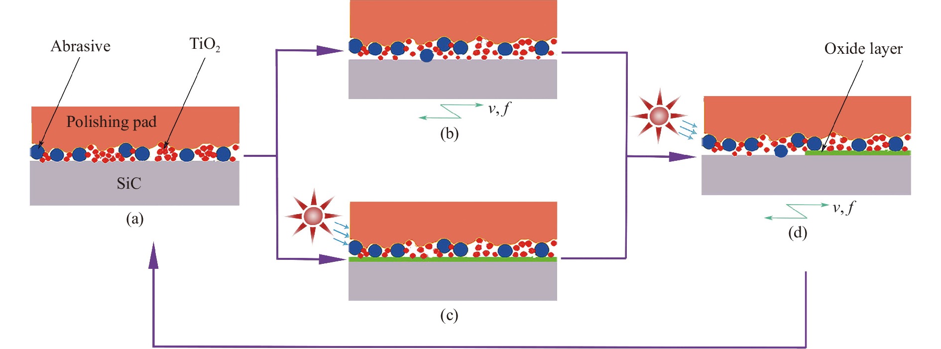
$$ {\text{SiC}} + 4 \cdot {\rm{OH}} + {{\rm{O}}_2} \to {\rm{SiO}}{_2} + 2{{\rm{H}}_2}{\rm{O}} + {\rm{CO}}{_2} $$ (4) 抛光过程如图1所示。光催化反应生成电子和空穴时间约为1 fs,电子和空穴复合的时间约为10~100 ns,光催化剂的反应时间约为10−3 s[17],复合的速率高于光催化剂反应速率,很容易造成电子和空穴没有参与到光催化反应就复合了。光催化剂发生了团聚(图1(a)),使部分光催化剂粒子得不到紫外光的照射,加剧了上述过程。在一定频率(f)和振幅(v)的振动下促进磨粒的分散,缓解光催化剂的团聚效应,实现磨粒和光催化剂均匀分布(图1(b));在紫外光的作用下,光催化剂在SiC表面生成了一层氧化层(图1(c)),在抛光压力和磨粒的磨削作用下,SiC与磨料相对运动,去除反应层,羟基自由基再与新的SiC表面反应,这样化学反应与机械作用交替进行,最终实现SiC材料的抛光(图1(d))。

图 1 光催化振动复合抛光原理图:(a)抛光初始状态;(b)振动条件下抛光过程;(c)光催化条件下抛光过程;(d)振动和光催化复合作用下抛光过程
Figure 1. Schematic diagram of photocatalytic-vibrated composite polishing: (a) Polished initial state; (b) Polishing process under vibration; (c) Polishing process under photocatalytic conditions; (d) Polishing process under the combined action of vibration and photocatalysis
由抛光原理图可以得出:在光催化振动复合抛光方法中,光催化反应和振动抛光需要协调配合。若光催化反应产生的氧化层不能及时去除,就会阻碍SiC表面产生新的氧化层,从而影响抛光效率,并且过多的氧化层会增加SiC的表面粗糙度。若振动抛光在抛光过程中起主导作用,光催化反应滞后,易在SiC表面产生划痕,影响SiC的表面精度。
-
甲基橙是一种常用的酸碱指示剂,也可以作为光催化剂的指示剂[18]。光催化剂在紫外光的照射下,产生强氧化剂羟基自由基·OH,羟基自由基与甲基橙发生反应,使甲基橙褪色。通过控制紫外光和振动条件,测定甲基橙溶液在不同条件下的褪色时间,探究紫外光催化下抛光液的氧化性。
-
根据TiO2电子发生跃迁从价带到导带所需的光能量计算波长为387.5 nm[19],因此选择波长365 nm的LED紫外面光源,它的光子能量达到了光催化剂被激发所需的能量。此节采用COUSZ公司的高功率LED紫外面光源。
实验中选择的光催化剂由化学试剂TiO2、过氧化氢、去离子水、磷酸配置而成,pH值调节为3,与甲基橙溶液混合,甲基橙呈现红色,实验参数如表1所示。将混合溶液放置在磁力搅拌器上搅拌均匀,然后进行对照实验,对照条件为是否有振动和光照,每4 min观察反应变化,如图2所示。
表 1 光催化氧化降解甲基橙实验参数
Table 1. Experimental parameters of photocatalytic oxidation degradation of methyl orange
Parameter Value UV wavelength/nm 365 TiO2/g·L−1 4 H2O2/vol% 3 pH 3 Frequency/Hz 200 Amplitude/V 20 UV light intensity/mW·cm−2 3000 
图 2 甲基橙褪色过程图
Figure 2. Map of fading process of methyl orange
-
由图2可知,将甲基橙加入到酸性抛光液后呈现为红色,在无紫外光照射下不变色,此时抛光液未产生羟基自由基;在一定强度紫外光照射下,抛光液开始褪色,在第4 min,抛光液出现了分层现象,上层为淡黄色,下层为粉色;在第12 min,下层逐渐褪为淡紫色;在第20 min时抛光液全部褪为淡黄色,此时并没有完全褪为白色。从这一过程中抛光液出现的分层现象可以看出,抛光液上层褪色速率高于下层抛光液。而在紫外光和振动条件下,在第4 min全部褪为粉色;在第12 min褪为白色。这一过程中,抛光液褪色均匀,没有分层现象,褪色效果也更加明显。
从上述过程可以得出:在紫外光照射下,抛光液产生了强氧化物,强氧化物使甲基橙褪色;振动对于加快抛光液的褪色时间是有效的,同时也加快了强氧化物的生成。在没有振动的条件下,抛光液每个部分氧化速率不同出现了分层现象,这是因为随着抛光液的沉淀和光催化剂的团聚,抛光液中的粒子影响了紫外光的透射,导致不同深度的抛光液曝光率不同,照射到最深层抛光液的紫外光强度减弱,影响了羟基自由基的生成。当加入振动后,振动降低了抛光液中的粒子团聚和沉淀,使光催化剂在抛光液中均匀分散,没有粒子团遮挡紫外光,不同深度的抛光液照射到的紫外光强度近似,二氧化硅表面生成自由电子和空穴的速率相同,促进了光催化反应均匀进行,所以没有出现分层现象,并且降解时间更快。
-
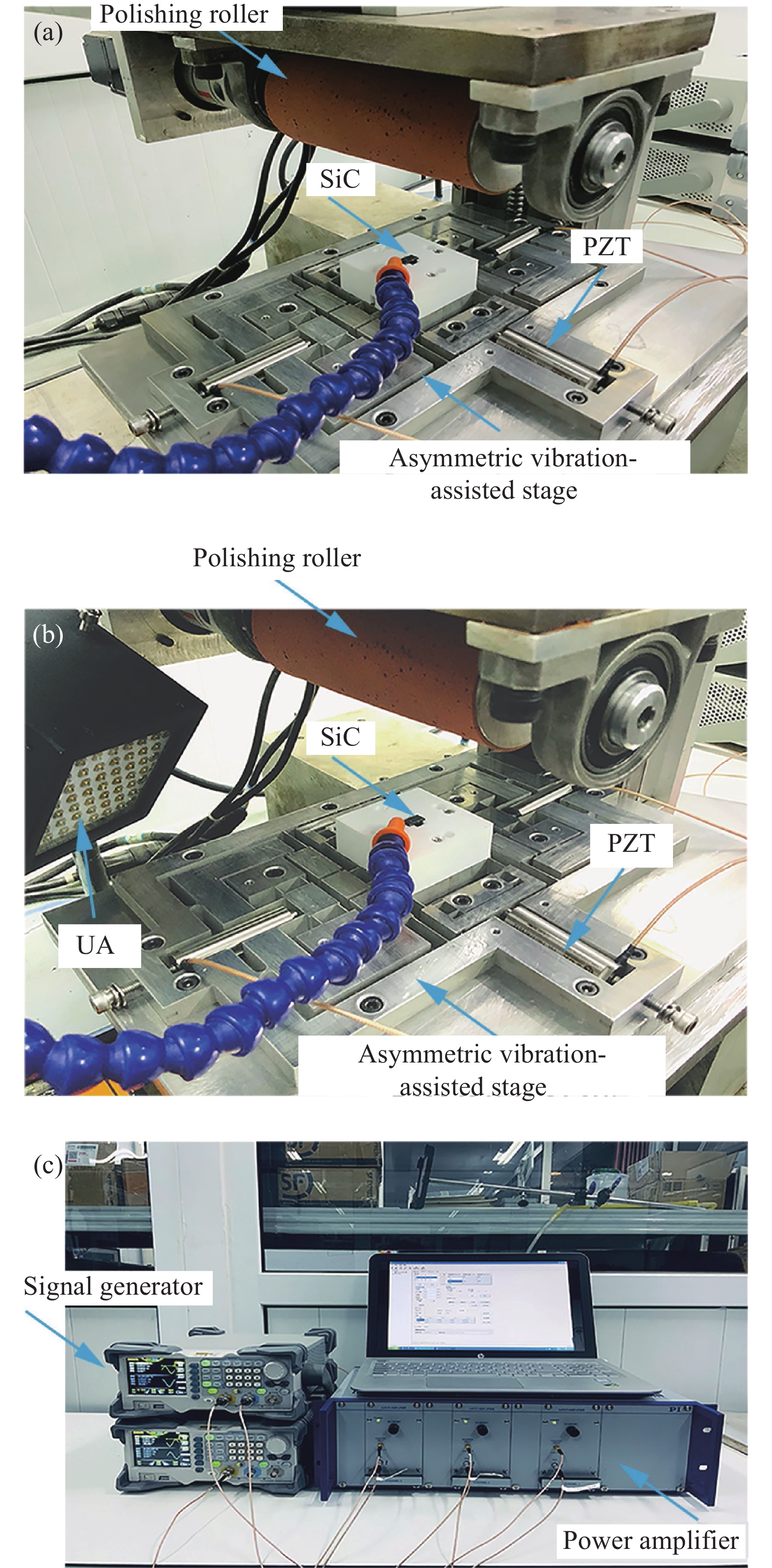
抛光实验采用自研辊式机床,振动辅助抛光装置,聚氨酯抛光垫,SiC尺寸为10 mm×10 mm×5 mm,将SiC固定在3D打印块上,3D打印块固定在振动辅助抛光装置上,利用信号发生器产生一定频率、振幅的电压信号,该信号通过功率放大器驱动压电,使振动辅助抛光装置产生振动,抛光垫粘贴在抛光辊上,抛光液通过电动供液系统输送到SiC与抛光辊之间,在抛光的同时,使用LED紫外面光源照射SiC表面,加工过程如图3所示。

图 3 SiC加工过程:(a)振动条件下加工过程;(b)光催化振动复合加工过程;(c)振动信号驱动图
Figure 3. SiC processing process diagram: (a) Machining process under vibration conditions; (b) Photocatalytic-vibrated composite processing process; (c) Vibration signal driver diagram
图3(a)为在没有紫外光、只有振动下的加工过程;图3(b)为光催化振动复合加工过程。振动辅助抛光装置在二维方向上振动,有利于抛光液中磨粒和光催化剂的均匀分散,降低抛光面上的划痕,促进光催化反应,使氧化层更加高效地去除。
-
为了获得高质量的加工表面,将抛光工艺分为粗抛和精抛。粗抛的目的是获得平整的加工基面,减少凹坑和凸起,然后通过精抛进一步降低表面粗糙度。粗抛选用的是全自动磨抛机(AutoPOL GP-1A,迈格仪器(苏州)有限公司),经过粗抛后的SiC表面粗糙度(Ra)为70 nm。
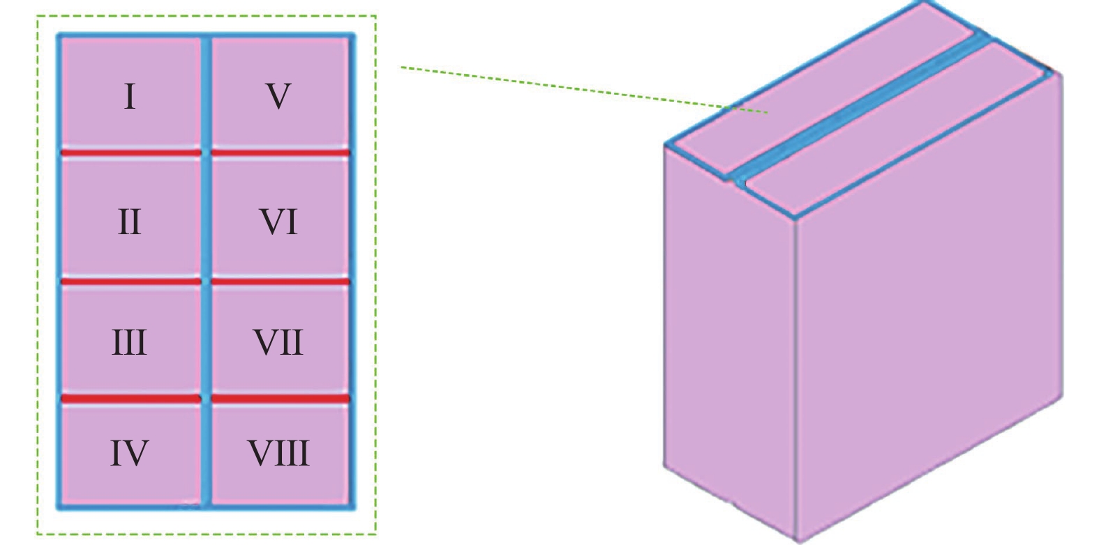
在粗抛的基础上对SiC基片进行精抛,工艺参数选择如下:辊式机床转速5 rad/s,进给0.2 mm/s,磨粒粒径1 μm,振动装置振幅30 μm,频率200 Hz,光照强度3000 mW/cm2。将磨粒与光催化剂混合制成抛光液,通过磁力搅拌器搅拌均匀。抛光后,将SiC放入无水乙醇中,清洗掉表面用于粘结的石蜡,最后放置在空气中晾干。采用白光干涉仪(Newview9000, Zygo)检测SiC表面粗糙度,测量位点如图4所示。
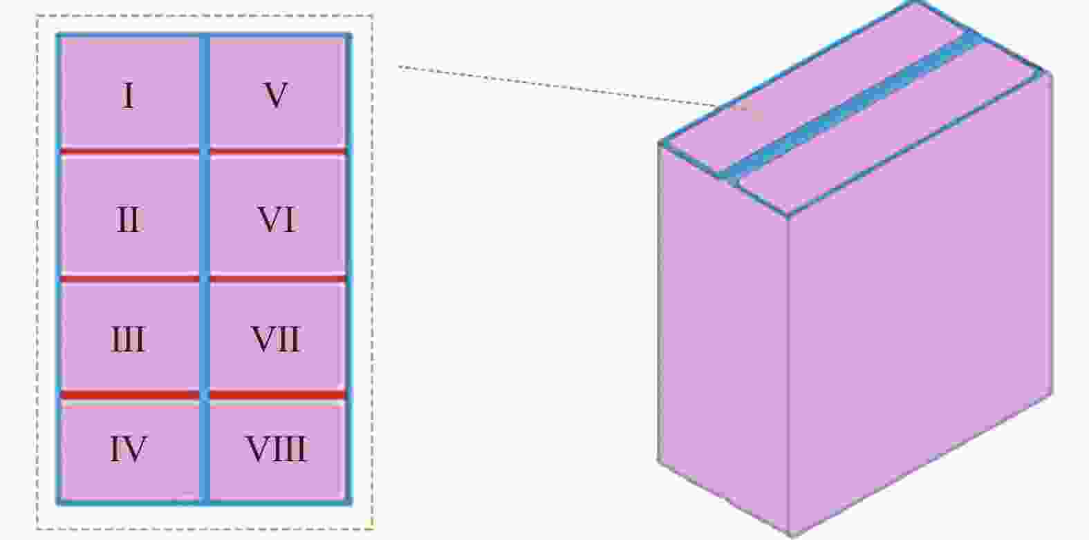
图 4 SiC测量位点图
Figure 4. Diagram of SiC measurement site
-
采用1 μm粒径金刚石磨粒抛光SiC,对SiC的表面粗糙度和表面形貌进行跟踪监测,对比光催化抛光、光催化和振动复合抛光的表面质量,如图5所示。图5(a)为SiC粗抛后的表面,图5(b)为在光催化条件下SiC表面效果,图5(c)为光催化和振动条件下抛光的表面效果,两个实验控制变量为是否存在振动作用,其余变量相同,选用SiC表面八个位点的粗糙度的平均值和标准差作为评价指标。

图 5 SiC抛光表面效果图:(a)粗抛后碳化硅表面;(b)光催化条件下碳化硅表面;(c)光催化和振动条件下碳化硅表面
Figure 5. Effect drawing of SiC polished surface: (a) SiC surface after rough polishing; (b) SiC surface under photocatalytic conditions; (c) SiC surfaces under photocatalytic and vibrational conditions
图5(b)和图5(c)中的表面纹理是振动的效果,表面纹理被打断是由于振动装置固有特性造成的。由图可知,光催化作用下SiC表面粗糙度为43 nm,光催化和振动复合抛光作用下SiC表面粗糙度为33 nm,光催化和振动复合抛光的表面粗糙度低于振动抛光。这是抛光液对SiC氧化形成氧化层的化学作用和磨料去除氧化层的机械作用共同作用的结果。
SiC光催化抛光和光催化振动抛光位点粗糙度如表2所示,可以看出,抛光前的SiC表面粗糙度范围在66~75 nm采用光催化抛光的SiC表面粗糙度范围在34~60 nm,而采用光催化和振动抛光方法的SiC表面粗糙度范围在31~39 nm。对比三个实验可以得出,光催化和振动结合的抛光方法粗糙度最低,抛光效果最好。由柱状图可知,抛光前SiC表面粗糙度均值最高,然后依次降低,光催化和振动抛光SiC表面粗糙度均值为34.875 nm。粗糙度标准差反映了SiC表面粗糙度是否均匀,三种抛光实验条件下,粗糙度标准差先升高再降低,在光催化条件下,SiC表面粗糙度不一致,表面质量还有待提高;在光催化和振动条件下,标准差最小,总体表面质量较好。
表 2 SiC表面粗糙度测量结果 (单位:nm)
Table 2. Measuremeent results of SiC surface roughness (Uint: nm)
Roughness Site I II III IV V VI VII VIII Before polishing 70 66 68 73 66 69 72 75 Photocatalytic 38 56 45 50 48 60 34 47 Photocatalysis and vibration 31 38 33 35 39 37 32 34 光催化振动复合抛光是光催化反应与振动抛光不断交替、相互协调的过程。振动抛光有较高的材料去除效率[20],分散磨粒和光催化剂,光催化反应生成的SiO2氧化层在磨粒作用下被去除,降低了振动抛光中的抛光力。由图6可以看出,光催化抛光粗糙度标准差较大,这是由于磨粒和光催化剂分散不均,导致抛光的不均匀;由表2可知,复合抛光比光催化抛光粗糙度平均提高了12.375 nm,可以表明,在同等条件下振动抛光对光催化抛光有促进作用。

图 6 SiC表面粗糙度统计图
Figure 6. Statistic of SiC surface roughness
光催化剂在SiC表面分布不均匀,光催化剂也存在团聚现象,使催化剂粒子不能充分得到紫外光的照射,进而影响了催化剂粒子价带电子的跃迁,阻碍了空穴和自由电子的生成,不能产生足够的羟基自由基,导致SiC表面氧化不均匀,甚至存在局部没有被氧化,然后在抛光辊的作用下,一部分区域是去除氧化层,一部分是机械去除,使SiC表面抛光压力,去除率不同,最终造成粗糙度差异较大。随着振动的引入,在光催化和振动的复合作用下,磨粒和光催化剂可以均匀地分布在SiC表面,每个光催化剂粒子受到的紫外光照射强度相同,促进光催化反应的进行,在SiC表面形成一层厚度均匀的氧化层,在抛光辊的作用下,SiC表面抛光压力、去除率近似,最终形成良好的抛光表面。
-
文中通过降解甲基橙实验,比较了有无振动条件下甲基橙的降解时间:其中,有振动条件下降解最快,12 min由红色褪为白色,振动缓解了光催化剂团聚现象,加快了甲基橙的降解过程。进行了有无振动条件下的抛光对比实验,结果表明:引入振动的抛光过程碳化硅陶瓷(SiC)表面粗糙度均值最低,标准差最小,表面最平整;采用转速5 rad/s、磨粒粒径1 μm、振幅30 μm、频率200 Hz、光照强度3000 mW/cm2的抛光工艺,可以获得表面粗糙度(Ra)为31 nm的光滑SiC表面。该实验也验证了光催化振动复合抛光的有效性。
Ultraviolet photocatalytic-vibrated composite polishing
-
摘要: 为了满足工业领域的不同要求,研究了碳化硅(SiC)陶瓷超光滑表面且无表面损伤的抛光工艺,提出了一种紫外光催化振动复合抛光新方法。基于紫外光催化反应理论,论述了光催化振动复合抛光的加工机理,进行了不同的实验。首先进行了甲基橙降解实验,研究了光催化振动复合抛光氧化性对振动的依赖关系;接着进行了紫外光催化振动复合抛光对比实验,研究了振动前后SiC的抛光效果,验证了新抛光方法的有效性。实验结果表明,光催化反应生成的强氧化性羟基自由基能够将高硬度的SiC氧化成质地较软的二氧化硅,振动的引入减少了光催化反应中光催化剂的团聚,提高了抛光过程中氧化和去除的均匀性,从而提高了抛光过程中SiC的表面质量,最终获得了粗糙度为31~39 nm的光滑表面。Abstract: In order to meet the different requirements of the industrial field, the polishing process of silicon carbide (SiC) ceramic with an ultra-smooth surface and no surface damage is studied, and a new method of ultraviolet photocatalytic-vibrated composite polishing is proposed. Based on the theory of ultraviolet photocatalytic reaction, the processing mechanism of photocatalytic-vibrated composite polishing was discussed, and different experiments were carried out. First, the methyl orange degradation experiment was carried out to study the dependence of the oxidative property of photocatalytic vibration composite polishing on vibration; then, the ultraviolet photocatalytic-vibrated composite polishing comparison experiment was carried out to study the polishing effect of SiC before and after vibration, and to verify the new polishing method’s effectiveness. The experimental results show that the strong oxidizing hydroxyl radicals generated by the photocatalytic reaction can oxidize high-hardness SiC into softer silica. The introduction of vibration not only reduces the agglomeration of the photocatalyst in the photocatalytic reaction, but also improves the uniformity of oxidation and removal, and thus improves the surface quality of SiC during polishing, and finally, a smooth surface with a roughness of 31–39 nm is obtained.
-
Key words:
- composite polishing /
- ultraviolet light /
- vibrate /
- silicon carbide ceramics /
- agglomeration
-
图 1 光催化振动复合抛光原理图:(a)抛光初始状态;(b)振动条件下抛光过程;(c)光催化条件下抛光过程;(d)振动和光催化复合作用下抛光过程
Figure 1. Schematic diagram of photocatalytic-vibrated composite polishing: (a) Polished initial state; (b) Polishing process under vibration; (c) Polishing process under photocatalytic conditions; (d) Polishing process under the combined action of vibration and photocatalysis
图 3 SiC加工过程:(a)振动条件下加工过程;(b)光催化振动复合加工过程;(c)振动信号驱动图
Figure 3. SiC processing process diagram: (a) Machining process under vibration conditions; (b) Photocatalytic-vibrated composite processing process; (c) Vibration signal driver diagram
图 5 SiC抛光表面效果图:(a)粗抛后碳化硅表面;(b)光催化条件下碳化硅表面;(c)光催化和振动条件下碳化硅表面
Figure 5. Effect drawing of SiC polished surface: (a) SiC surface after rough polishing; (b) SiC surface under photocatalytic conditions; (c) SiC surfaces under photocatalytic and vibrational conditions
表 1 光催化氧化降解甲基橙实验参数
Table 1. Experimental parameters of photocatalytic oxidation degradation of methyl orange
Parameter Value UV wavelength/nm 365 TiO2/g·L−1 4 H2O2/vol% 3 pH 3 Frequency/Hz 200 Amplitude/V 20 UV light intensity/mW·cm−2 3000  下载: 导出CSV
表 2 SiC表面粗糙度测量结果 (单位:nm)
Table 2. Measuremeent results of SiC surface roughness (Uint: nm)
Roughness Site I II III IV V VI VII VIII Before polishing 70 66 68 73 66 69 72 75 Photocatalytic 38 56 45 50 48 60 34 47 Photocatalysis and vibration 31 38 33 35 39 37 32 34
下载: 导出CSV
-
[1] Mai Yubing, Xie Xinrong. The research progress of the third generation semiconductor materials SiC [J]. Guangdong Chemical Industry, 2021, 48(9): 151-152, 155. (in Chinese) [2] Liu Xinyang. Reflections on development and innovation trend of 5 G semiconductor industry [J]. ZTE Technology Journal, 2021, 27(4): 51-52. (in Chinese) [3] Wang Xing, Bao Jianxuan. Effects of nano-SiC powder on rheological behavior of SiC slurry and mechanical properties of RBSC [J]. Infrared and Laser Engineering, 2014, 43(S1): 197-202. (in Chinese) [4] Zhang Lei, Shao Mengqi, Xue Zhipeng, et al. Optomechanical structure design and experiment of high-resolution video camera for micro-nano satellite (Invited) [J]. Infrared and Laser Engineering, 2021, 50(10): 20210447. (in Chinese) [5] Suzuki H, Hamada S, Okino T, et al. Ultraprecision finishing of micro-aspheric surface by ultrasonic two-axis vibration assisted polishing [J]. CIRP Annals-Manufacturing Technology, 2010, 59(1): 347-350. doi: 10.1016/j.cirp.2010.03.117 [6] Zhu Z, To S, Zhu W, et al. Optimum design of a piezo-actuated tri-axial compliant mechanism for nano-cutting [J]. IEEE Transactions on Industrial Electronics, 2017, 65(8): 6362-6371. [7] Zhao D, Zhu Z, Huang P, et al. Development of a piezoelectrically actuated dual-stage fast tool servo [J]. Mechanical Systems and Signal Processing, 2020, 144: 106873. doi: 10.1016/j.ymssp.2020.106873 [8] Gu Y, Duan X, Lin J, et al. Design, analysis, and testing of a novel 2-DOF vibration-assisted polishing device driven by the piezoelectric actuators [J]. The International Journal of Advanced Manufacturing Technology, 2020, 111(1-2): 1-23. doi: 10.1007/s00170-020-06079-y [9] Chen X, Gu Y, Lin J, et al. Study on subsurface damage and surface quality of silicon carbide ceramic induced by a novel non-resonant vibration-assisted roll-type polishing [J]. Journal of Materials Processing Technology, 2020, 282: 116667. doi: 10.1016/j.jmatprotec.2020.116667 [10] Lu Jiabin, Xiong Qiang, Yan Qiusheng, et al. Effect of chemical reaction rate in ultraviolet photocatalytic auxiliary SiC polishing process [J]. Surface Technology, 2019, 48(11): 148-158. (in Chinese) [11] He Yan, Yuan Zewei, Duan Zhenyun, et al. High-productively ultraprecise polishing technique polishing of single crystal SiC wafer [J]. Journal of Harbin Institute of Technology, 2019, 51(1): 115-121. (in Chinese) [12] Yin T, Zhao P, Doi T, et al. Effect of using high-pressure gas atmosphere with UV photocatalysis on the CMP characteristics of a 4H-SiC substrate [J]. ECS Journal of Solid State Science and Technology, 2021, 10(2): 024010. [13] Zhou Y, Pan G, Zou C, et al. Chemical mechanical polishing (CMP) of SiC wafer using photo-catalyst incorporated pad [J]. ECS Journal of Solid State Science & Technology, 2017, 6(9): P603-P608. [14] Gao B, Zhai W J, Zhai Q, et al. Novel photoelectrochemically combined mechanical polishing technology for scratch-free 4H-SiC surface by using CeO2-TiO2 composite photocatalysts and PS/CeO2 core/shell abrasives [J]. Applied Surface Science, 2021, 570: 151141. doi: 10.1016/j.apsusc.2021.151141 [15] Fagan R, Mc Cormack D E, Dionysiou D D, et al. A review of solar and visible light active TiO2 photocatalysis for treating bacteria, cyanotoxins and contaminants of emerging concern [J]. Materials Science Semiconductor Processing, 2016, 42(1): 2-14. [16] Lu Jiabin, Xiong Qiang, Yan Qiusheng, et al. Effects of lights modes and abrasives on UV-photocatalysis assisted polishing of 6H-SiC single crystal [J]. Diamond & Abrasives Engineering, 2019, 39(3): 9. (in Chinese) [17] 何艳. 光催化辅助抛光碳化硅晶片工艺及机理研究[D]. 沈阳: 沈阳工业大学, 2019. He Yan. Study on the technique and mechanism of photocatalysis assisted polishing silicon carbide wafer[D]. Shenyang: Shenyang University of Technology, 2019. (in Chinese) [18] Khan S A, Zahera M, Khan I A, et al. Photocatalytic degradation of methyl orange by cadmium oxide nanoparticles synthesized by the sol-gel method [J]. Optik, 2022, 251: 168401. [19] Liu Jindong, Li Haorong, Lin Guoqing, et al. Research progres of titanium dioxide in the field of solar cells [J]. Guangdong Chemical Industry, 2021, 48(20): 117, 96. (in Chinese) [20] Chee S K, Suzuki H, Okada M, et al. Precision polishing of micro mold by using piezoelectric actuator incorporated with mechanical amplitude magnified mechanism [J]. Advanced Materials Research, 2011, 325: 470-475. doi: 10.4028/www.scientific.net/AMR.325.470 -

 点击查看大图
计量
- 文章访问数: 163
- HTML全文浏览量: 36
- PDF下载量: 29
- 被引次数: 0


