


 下载:
下载:


-
飞秒激光脉冲具有峰值功率高、脉冲宽度窄和光谱宽的特点,目前已在物理、化学、材料生物等基础学科领域[1-5]和精密测距、激光加工等研究领域[6-8]被广泛应用。飞秒脉冲光纤激光器相比于固体激光器具有长度长、结构紧凑、柔韧性好和散热性能好等特点,在近年来迅速发展成为超短脉冲激光领域内的热点之一。同时,如何获得高能量、高质量的飞秒脉冲也是国际光纤光学科研工作者关注的焦点。在飞秒级光纤放大系统中,种子源对于整个系统的输出和稳定性起着至关重要的作用,通常采用飞秒量级的光纤锁模激光器作为种子源。但是,相比于皮秒激光器,飞秒激光器的结构更加复杂,造价昂贵且稳定性不高。同时,飞秒激光器较宽的初始光谱在非线性放大过程中容易受到增益整形作用的影响,从而降低了输出脉冲的质量。因此,采用光纤皮秒激光器作为种子源,对于在光纤放大器中获得高质量的飞秒脉冲输出具有重要意义。
孤子压缩和非线性脉冲压缩是实现脉冲从皮秒量级过渡到飞秒量级的两种常用方法。孤子压缩可以在具有负色散的普通单模光纤中实现小于100 fs的脉冲输出[9],但是输出能量有限,为纳焦耳量级,虽然利用充有惰性气体的空芯光纤作为非线性介质可以提高输出能量[10],但是结构复杂、稳定性差。而非线性脉冲压缩并不需要复杂的光纤结构,因此被广泛应用[11-12]。为了近一步提升输出的单脉冲能量,可以在光纤放大器中利用非线性光谱展宽作用实现皮秒脉冲到飞秒脉冲的压缩。但是,脉冲在进行非线性放大的过程中,自相位调制(Self-phase modulation,SPM)效应会引入无法压缩的非线性啁啾,严重降低了输出脉冲的质量。自相似放大技术概念的引入良好地解决了这一问题。
自相似放大技术是指种子源在正色散增益光纤放大器中传输时,主动利用光纤中的SPM效应,在放大信号光脉冲的同时展宽光谱,输出可通过压缩去啁啾得到近变换极限的线性啁啾抛物线型脉冲。2000年,Fermann M E等人首次在总增益30 dB的掺镱光纤中实现了自相似放大,获得了脉冲宽度68 fs,峰值功率80 kW的抛物线脉冲输出[13]。在之后的近20年间,自相似放大的理论和实践日趋成熟[14-16],但自相似放大器的种子源大多采用飞秒激光器,而皮秒激光器却鲜有报道[17],如何在自相似放大中实现皮秒脉冲到飞秒脉冲的压缩越来越受到科研工作者的关注。
随着自相似理论的不断发展,应用也越加广泛,但其仍存在诸多研究空白,其中就包括增益分布对自相似放大过程的影响。光纤中的增益分布是指光纤中不同位置的增益大小的分布趋势,增益分布的不同会直接影响到反转粒子数密度的分布,从而使脉冲放大过程的峰值功率和单脉冲能量发生变化,改变放大过程中的非线性效应和演化速度,进而影响自相似放大过程。可以说,光纤中不同的增益分布会产生截然不同的自相似放大过程,通过改变增益分布可以有效减弱增益整形作用的影响,同时提高脉冲在自相似放大过程中的演化效率和稳定性,在基于皮秒种子源光纤放大器中得到高质量的飞秒激光脉冲输出。
文中建立了以掺Yb3+光纤为基础的自相似脉冲放大数值模型,模拟研究了皮秒脉冲在不同增益分布下的自相似放大过程。模拟结果显示,在不同的增益分布下,皮秒脉冲自相似放大器中都可以得到高质量的百飞秒脉冲输出,实现最佳的自相似放大过程。在相同的放大器参数下,信号光脉冲在正向泵浦方式下的自相似演化速度快于反向泵浦;对于不同的放大器参数,正向泵浦更适合中心波长较长、入射能量较低的信号光脉冲,反向泵浦更适合中心波长较短、入射能量较高的信号光脉冲。
-
在数值模拟中,建立了掺Yb3+双包层光纤非线性脉冲放大器的数值模型,其中光纤放大器中的色散和非线性过程由非线性薛定谔方程描述,光纤放大器中的增益由速率方程和传输方程来描述。为了简化复杂的理论模型,首先忽略了较弱的高阶色散和高阶非线性效应带来的影响,主要考虑脉冲在增益光纤中的群速度色散和自相位调制作用,非线性薛定谔方程可简化为公式(1);其次,在不考虑激发态吸收和背景损耗的条件下,由于信号光的脉冲间隔远小于上能级寿命,等效于连续信号光,可以用稳态方程式(2)~(5)来表示。稳态方程组是关于传输距离z的耦合常微分方程,可用四阶龙格-库塔公式(Runge-Kutta)以迭代的方法求解。通过结合公式(2)~(5)可算出脉冲在光纤长度z上的每一小段dz中放大的结果,然后计算得出脉冲在放大后的振幅,最后将其代入公式(1)中利用分步傅里叶算法[18]求解,并在整个增益光纤长度上依次迭代计算即可较为准确地模拟出放大脉冲在群速度色散和自相位调制共同作用下的自相似演化情况。
$$i\frac{{\partial A({\textit{z}},t)}}{{\partial {\textit{z}}}} = \frac{{{\beta _2}}}{2}\frac{{{\partial ^2}A({\textit{z}},t)}}{{\partial {t^2}}} - \gamma {\left| {A({\textit{z}},t)} \right|^2}A({\textit{z}},t)$$ (1) $${N_2}({\textit{z}}) = \frac{{\dfrac{{{\lambda _p}}}{{{A_p}hc}}{\sigma _a}({\lambda _p}){P_p}({\textit{z}}) + \dfrac{1}{{{A_s}hc}} \displaystyle\sum\limits_k {{\lambda _k}{\sigma _a}({\lambda _k}){P_s}({\lambda _k},{\textit{z}})} }}{{\dfrac{{{\lambda _p}}}{{{A_p}hc}}\left[ {{\sigma _a}({\lambda _p}) + {\sigma _e}({\lambda _p})} \right]{P_p}({\textit{z}}) + \dfrac{1}{\tau } + \dfrac{1}{{{A_s}hc}} \displaystyle\sum\limits_k {{\lambda _k}\left[ {{\sigma _a}({\lambda _k}) + {\sigma _e}({\lambda _k})} \right]{P_s}({\lambda _k},{\textit{z}})} }}{N_{Yb}}$$ (2) $${N_1}({\textit{z}}) = {N_{Yb}} - {N_2}({\textit{z}})$$ (3) $$ - \frac{{{\rm d}{P_p}({\textit{z}})}}{{{\rm d}{\textit{z}}}} = \left[ {{\sigma _e}\left( {{\lambda _p}} \right){N_2}({\textit{z}}) - {\sigma _a}({\lambda _p}){N_1}({\textit{z}})} \right]{P_p}({\textit{z}}){\varGamma _p}$$ (4) $$\frac{{{\rm d}{P_s}({\textit{z}})}}{{{\rm d}{\textit{z}}}} = \sum\limits_k {\left[ {{\sigma _e}\left( {{\lambda _k}} \right){N_2}({\textit{z}}) - {\sigma _a}({\lambda _k}){N_1}({\textit{z}})} \right]{P_s}({\textit{z}},{\lambda _k}){\varGamma _s}} $$ (5) 在公式(1)中,A(z,t)表示延时系脉冲的慢变包络,β2
和γ分别表示光纤中的二阶色散和非线性系数。在公式(2)~(5)中,为了简化运算,假设光纤沿长度的方向掺杂均匀,掺杂密度为NYb,信号光和泵浦光在光纤的横截面上均匀分布,面积分别为As和Ap,Γs和Γp分别表示信号光和泵浦光的功率填充因子。τ表示激光上能级寿命,N2 (z)和N1(z)表示激光上、下能级粒子数密度分布,Pp(z)和Ps(z)表示泵浦光和信号光的平均功率,λp表示泵浦光的中心波长,λk表示脉冲光谱被分成K个波段后的每个波段的中心波长,σa(λk)和σe(λk)分别表示在λk处Yb3+离子的吸收截面和发射截面,Ps(z,λk)表示λk处信号光平均功率。 在自相似放大理论中,常引入M因子来描绘自相似脉冲的演化程度[19],如公式(6)所示:
$${M^2} = \frac{{\displaystyle\int {{{\left( {{{\left| A \right|}^2} - {{\left| {{A_p}} \right|}^2}} \right)}^2}{\rm d}t} }}{{{{\displaystyle\int {\left| A \right|} }^4}{\rm d}t}}$$ (6) 式中:A为自相似放大脉冲的振幅包络;Ap为抛物线脉冲的振幅包络。M 因子表示在相同的脉冲能量和峰值功率下,脉冲时域强度|A|2与抛物线脉冲时域强度|Ap|2的差距。M 因子的数值越小,脉冲越接近抛物线形;M 因子的数值越大,脉冲越偏离抛物线形,即偏离自相似 演化。通常情况下,当 M≤0.04 时,即可近似认为脉 冲与抛物线形相一致,实现了自相似演化。
评价去啁啾后的放大脉冲质量通常用Strehl ratio(SR)表示[20],如公式(7)所示:
$$SR{\rm{ = }}\frac{{1/{{\displaystyle\int {\left| {{A_c}} \right|} }^2}{\rm d}t}}{{1/\displaystyle\int {{{\left| {{A_{TL}}} \right|}^2}} {\rm d}t}}$$ (7) 式中:Ac为压缩后放大脉冲的时域包络;ATL为脉冲光谱对应的傅里叶变换极限脉冲的时域包络。由公式(7)可以看出,Strehl ratio取1时表示光谱对应的傅里叶变换极限脉冲。同时,Strehl ratio越接近1,说明还原后的去啁啾放大脉冲越接近变换极限脉冲,放大过程中脉冲主要积累线性啁啾,自相似演化程度越高。
在超短激光脉冲自相似放大的研究中,已经较为详细地探讨了脉冲宽度对自相似演化过程的影响[21],发现脉冲宽度在1 ps附近具有较好的演化效果。基于以上研究成果,笔者在模拟中采用1.2 ps的无啁啾高斯脉冲作为种子源,脉冲重复频率50 MHz,剩余模拟参数见表1,未设定的参数将作为讨论条件出现在模拟中。
-
增益分布是指光纤中不同位置的增益系数的分布,其由反转集居数密度分布决定,与泵浦方式、光纤长度、泵浦功率(总增益系数)密切相关。在自相似放大过程中,增益分布直接决定脉冲能量的增益,影响放大中的非线性过程,因此不同的增益分布产生不同的自相似放大过程。所以,只有选择合适的增益分布,才能得到最佳的自相似放大结果,实现信号光脉冲从皮秒量级到飞秒量级的过渡,得到高质量、窄脉宽的脉冲输出。
首先探究泵浦方式对自相似放大过程和结果的影响。图1(a)表示采用正向泵浦方式的脉冲放大过程,泵浦源放置于增益光纤之前,信号光与泵浦光沿增益光纤的传输方向相同。图1(b)表示采用反向泵浦方式的脉冲放大过程,泵浦源放置于增益光纤之后,信号光与泵浦光沿增益光纤的传输方向相反。
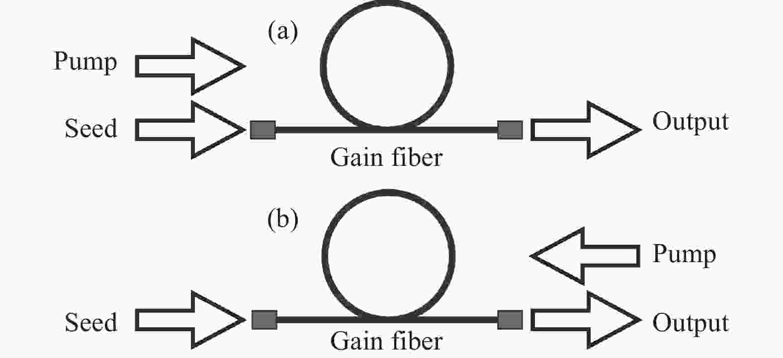
图 1 自相似放大在不同泵浦方式下的示意图。(a)正向泵浦,(b)反向泵浦
Figure 1. Self-similar amplification in different pump schemes. (a) Forward pump, (b) backward pump
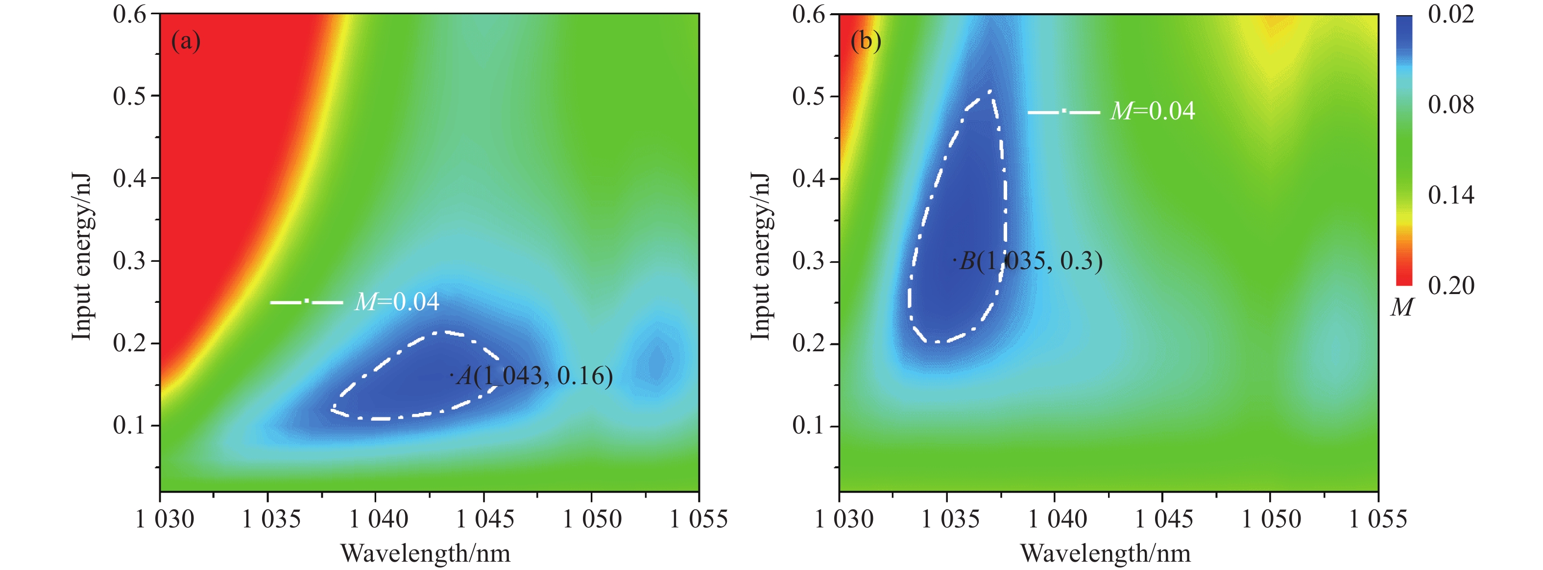
对于自相似放大,信号光脉冲能量是决定是否能实现自相似演化的重要因素之一,也决定了演化速度。同时根据增益谱线的分布趋势[18],信号光脉冲的中心波长决定了增益整形作用对自相似演化的影响,所以也是重要参数之一。这样,为了分析信号光脉冲能量与中心波长对自相似放大的影响,在数值模拟中遍历不同的信号光中心波长和脉冲能量,固定总增益30 dB和入射脉宽1.2 ps,在2 m的增益光纤中获得这两种参量不同取值时放大输出脉冲的M因子,形成如图2所示的伪彩图。横坐标表示信号光脉冲的中心波长,纵坐标表示信号光脉冲的入射能量,伪彩图的颜色代表M因子的强度,达到自相似演化参数区域为白色曲线(M=0.04的等高线)围成的蓝色区域。在此基础上,分析不同泵浦方式下自相似放大的特点。
从图2可以看出,不同泵浦方式下M因子分布不同,这说明不同增益分布对信号光脉冲的自相似演化参数区域影响较大。图2(a)中的A点表示当信号光脉冲中心波长为1 043 nm,入射能量为0.16 nJ时,在正向泵浦方式下进行自相似演化时达到的最佳输出点,此时M因子的值为0.031;图2(b)中的B点表示当信号光脉冲中心波长为1 035 nm,入射能量为0.3 nJ时,在反向泵浦方式下进行自相似演化时达到的最佳输出点,此时M因子的值为0.022。下面对A点和B点的信号光脉冲经自相似放大得到的输出脉冲指标进行对比。

图 2 不同泵浦方式下放大脉冲的M因子与脉冲中心波长和入射能量关系的伪彩图。(a)正向泵浦,(b)反向泵浦。A和B点分别表示M值在(a)和(b)的最低点,即自相似演化的最佳点
Figure 2. M-factors versus pulse central wavelength and input energy of amplified pulses in different pump schemes. (a) Forward pump, (b) backward pump. Point A and B represent the minimum value of M-factors in (a) and (b), which are the best points of self-similar evolution
从图3可以看出,A点和B点的放大光谱产生了明显的由SPM效应引起的光谱调制,说明SPM效应在非线性放大过程中起关键作用,这也是自相似放大的重要特征。同时,放大脉冲的时域形状与抛物线形拟合完全重合,说明已演化到抛物线形。在图3(a)中,A点得到的压缩后脉冲基底较小,脉冲质量较好,其时域宽度为133 fs,由光谱计算得到的变换极限脉冲宽度为132 fs,在误差允许的范围内,两者基本相等。去啁啾脉冲的斯特列尔比SR为0.924,说明放大过程只积累了线性啁啾,经腔外压缩后达到了变换极限,放大过程实现了自相似演化。在图3(b)中,B点得到的压缩后脉冲时域宽度为105 fs,由光谱计算得到的变换极限脉冲宽度为104.8 fs,去啁啾脉冲的斯特列尔比SR为0.916,说明在B点也实现了自相似放大,并通过压缩得到了近变换极限的脉冲输出。这里可以得出结论,无论采用哪种泵浦方式,都可以采用皮秒信号光脉冲实现自相似放大过程,得到高质量的百飞秒量级的脉冲输出。
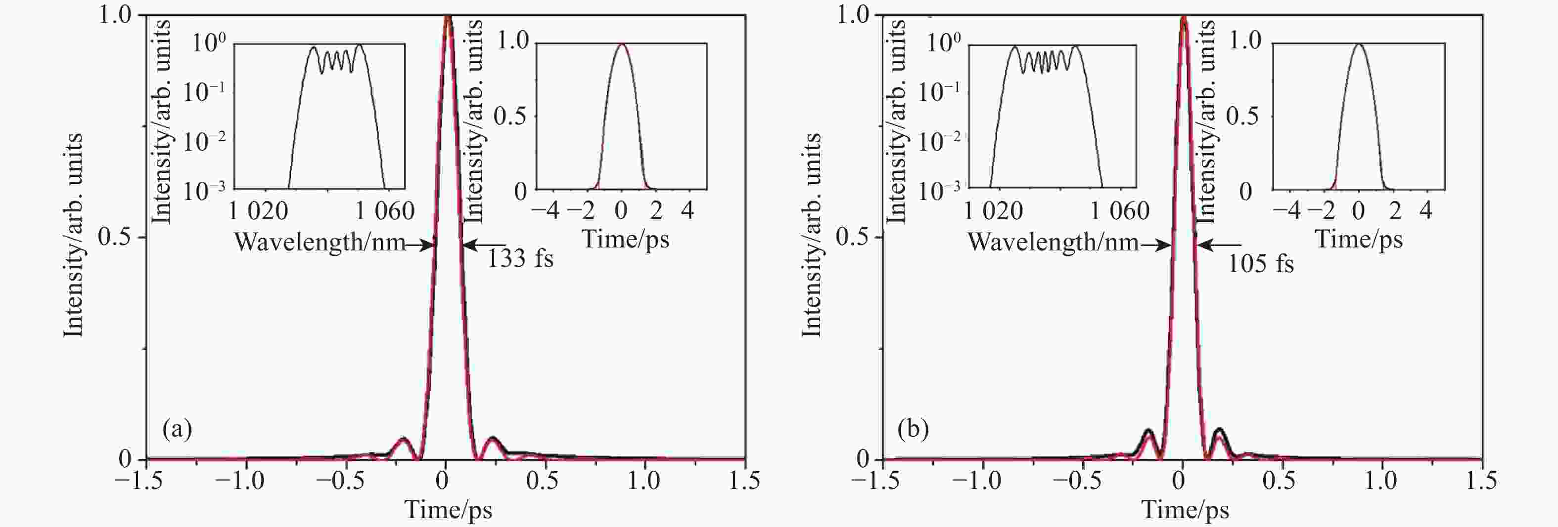
图 3 信号光脉冲在不同泵浦方式下的放大结果。(a) A点处的信号光脉冲在正向泵浦下传输到光纤2 m处的去啁啾时域强度,(b) B点处的信号光脉冲在反向泵浦下传输到光纤2 m处的去啁啾时域强度。黑色实线表示信号光脉冲,红色实线表示对应的变换极限脉冲。内插图分别为对应的光谱(左)和压缩前脉冲时域(右),其中黑线和红线代表信号光脉冲和抛物线拟合
Figure 3. Amplification results of seed pulses in different pump schemes. (a) De-chirped pulse profile of the seed pulse of point A transmitting to the end of the 2 m-long fiber in forward-pumping scheme, (b) de-chirped pulse profile of the seed pulse of point B transmitting to the end of the 2 m-long fiber in backward-pumping scheme. Black lines and red lines are seed pulses and transform-limited pulses. Insets: corresponding spectra (left) and amplified pulses before compression (right). Black lines and red lines are seed pulses and parabolic fittings
根据图2伪彩图所呈现的规律,正向泵浦与反向泵浦方式下的自相似演化区域没有交集,即不存在同一信号光脉冲在不同增益分布下同时实现自相似放大输出,这是因为在不同的泵浦方式下脉冲的自相似演化速度是不同的,在增益光纤中传输时正向泵浦方式下脉冲的自相似演化快于反向泵浦。下面通过模拟同一信号光脉冲在正、反泵浦方式下的自相似演化过程来进一步解释这个结论。
(1) 信号光脉冲参数同为正向泵浦方式下的最佳自相似演化点
将信号光脉冲设为图2(a)中A点处的参数,在2 m长的增益光纤中分别采用正向泵浦与反向泵浦方式进行放大,其自相似演化过程如图4所示。
图4(a)表示脉冲放大过程中峰值功率和M因子随光纤长度的演化。从图中可以看出,在两种泵浦方式下,M因子都是单调递减的,说明都在向抛物线形自相似放大演化。正向泵浦下,M因子在输出端达到最小值0.031,放大脉冲演化到自相似子;反向泵浦下,M因子在输出端也达到最小值0.071,但放大脉冲并未过渡到抛物线形。从峰值功率来看,在两种泵浦方式下都是单调递增的,正向泵浦在光纤的后半段上升速度明显降低,在光纤输出端达到87 kW后基本不再增加;反向泵浦在放大过程中上升的速度越来越快,在光纤输出端达到最大值98 kW。这是因为在反向泵浦方式下,反转粒子数分布沿增益光纤长度方向单调递增,离光纤输出端越近,增益越高。整个放大过程中,正向泵浦方式下的峰值功率在信号光脉冲传输到光纤末段前一直高于反向泵浦,说明在增益光纤中产生的非线性效应更强。图4(b)表示放大过程中的脉冲宽度和10 dB光谱宽度随光纤长度的变化。可以看出,在整个放大过程中脉冲宽度和光谱宽度都是单调递增的,脉冲在时域和频域上同时展宽。这是因为脉冲在正色散光纤中传输时,非线性效应的产生需要一定的单脉冲能量,而自相位调制效应与脉冲的时域形状相关,脉冲时域形状的变化又会反过来展宽光谱,使光谱和脉冲同时展宽。从图中还可以看出,正向泵浦下的时域和频域展宽位置都早于反向泵浦,展宽量也更高。结合图4(a)和(b)分析可知,脉冲在正向泵浦方式下峰值功率提升更快,脉宽和谱宽展宽量更高,M值下降和脉宽与谱宽展宽的位置更早,说明正向泵浦下信号光脉冲过渡到自相似演化过程中的非线性效应更强,自相似演化速度也更快。图4(c)和(d)分别表示正向泵浦和反向泵浦方式下脉冲在光纤中放大时的光谱演化伪彩图,可以明显看出,正向泵浦下光谱的展宽位置要早于反向泵浦,并且光谱的展宽量更高,这与图4(b)中的结果一致,更直观地体现出正向泵浦下自相似演化速度更快。
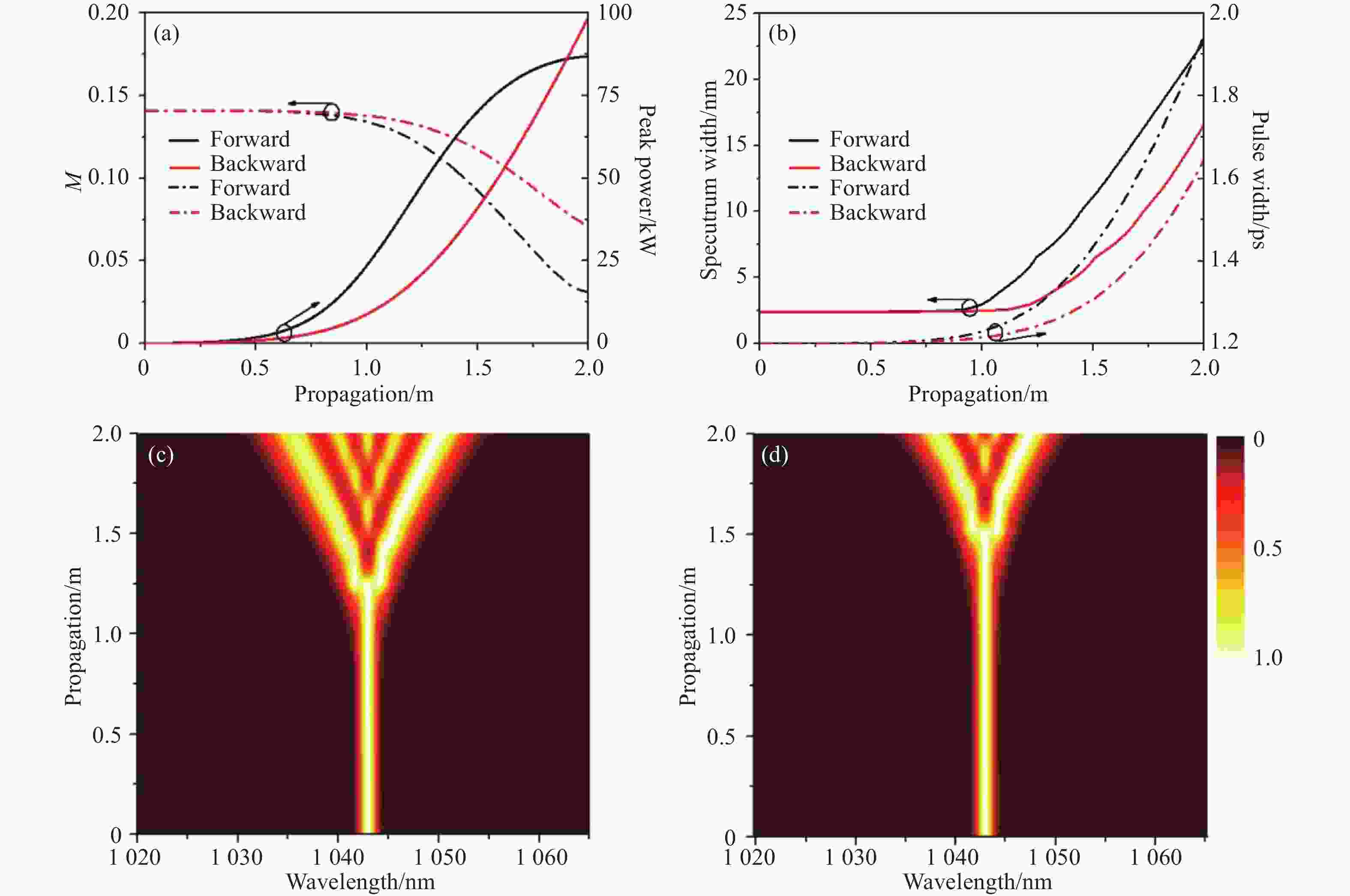
图 4 A点处的信号光脉冲在正、反泵浦方式下的演化过程。(a) 峰值功率(实线)与M因子(点划线),(b) 10 dB光谱宽度(实线)与脉冲宽度(点划线)。黑色曲线表示正向泵浦,红色曲线表示反向泵浦。(c) 正向泵浦下的光谱演化,(d) 反向泵浦下的光谱演化
Figure 4. Evolution of the seed pulse of point A in forward-pumping and backward-pumping schemes. (a) Peak power (solid) and M-factor (dash-dot), (b) 10 dB spectral width (solid) and pulse width(dash-dot). Black lines and red lines represent forward pump and backward pump. (c) Spectral evolution in forward-pumping scheme, (d) Spectral evolution in backward-pumping scheme
(2) 信号光脉冲参数同为反向泵浦方式下的最佳自相似演化点
将信号光脉冲设为图2(b)中B点处的参数,在2 m长的增益光纤中分别采用正向泵浦与反向泵浦方式进行放大,其自相似演化过程如图5所示。
从图5(a)可以看出,正向泵浦的M因子先下降后上升,经历了自相似演化过渡后又逐渐偏离自相似的过程;而反向泵浦的M值单调递减,在输出端达到最小值0.022。脉冲在正向泵浦下的峰值功率快速增长后在光纤后端保持135 kW不变,在反向泵浦下峰值功率单调递增且增幅越来越大。图5(b)中脉冲宽度和光谱宽度的变化与图4(b)中的趋势相同,正向泵浦下脉宽和光谱展宽量均高于反向泵浦,展宽的位置早于反向泵浦。从图5(c)和(d)可以看出正向泵浦下光谱的展宽位置要早于反向泵浦,光谱的展宽量也更高。但由于增益整形作用的破坏,正向泵浦下放大脉冲的光谱在快速展宽后突破了增益带宽的边界,光谱中心向长波长方向偏移与增益中心失配,使脉冲时域出现不对称并发生畸变。在这种情况下,正向泵浦下脉冲的自相似演化速度也快于反向泵浦,但由于受到增益窄化的影响,后期的演化开始偏离自相似过程。
以上讨论了不同的泵浦方式对自相似放大过程的影响,为了更直观地进行对比,将不同增益分布对自相似放大结果的影响通过多组伪彩图的形式呈现出来。通过改变模拟中的光纤长度和总增益系数来探究信号光脉冲的自相似参数区域并进行比较。模拟中仍采用1.2 ps的无啁啾高斯脉冲为信号光脉冲,脉冲的重复频率为50 MHz。对信号光脉冲的单脉冲能量和中心波长进行扫描,分别模拟了不同增益光纤长度下和不同总增益系数下的放大结果。

图 5 B点处的信号光脉冲在正、反泵浦方式下的演化过程。(a) 峰值功率(实线)与M因子(点划线),(b)10 dB光谱宽度(实线)与脉冲宽度(点划线),黑色曲线表示正向泵浦,红色曲线表示反向泵浦。(c) 正向泵浦下的光谱演化,(d) 反向泵浦下的光谱演化
Figure 5. Evolution of the seed pulse of point B in forward-pumping and backward-pumping schemes. (a) Peak power (solid) and M-factor(dash-dot), (b) 10 dB spectral width (solid) and pulse width(dash-dot). Black lines and red lines represent forward pump and backward pump. (c) Spectral evolution in forward-pumping scheme, (d) Spectral evolution in backward-pumping scheme
(3)总增益系数相同,增益光纤长度不同
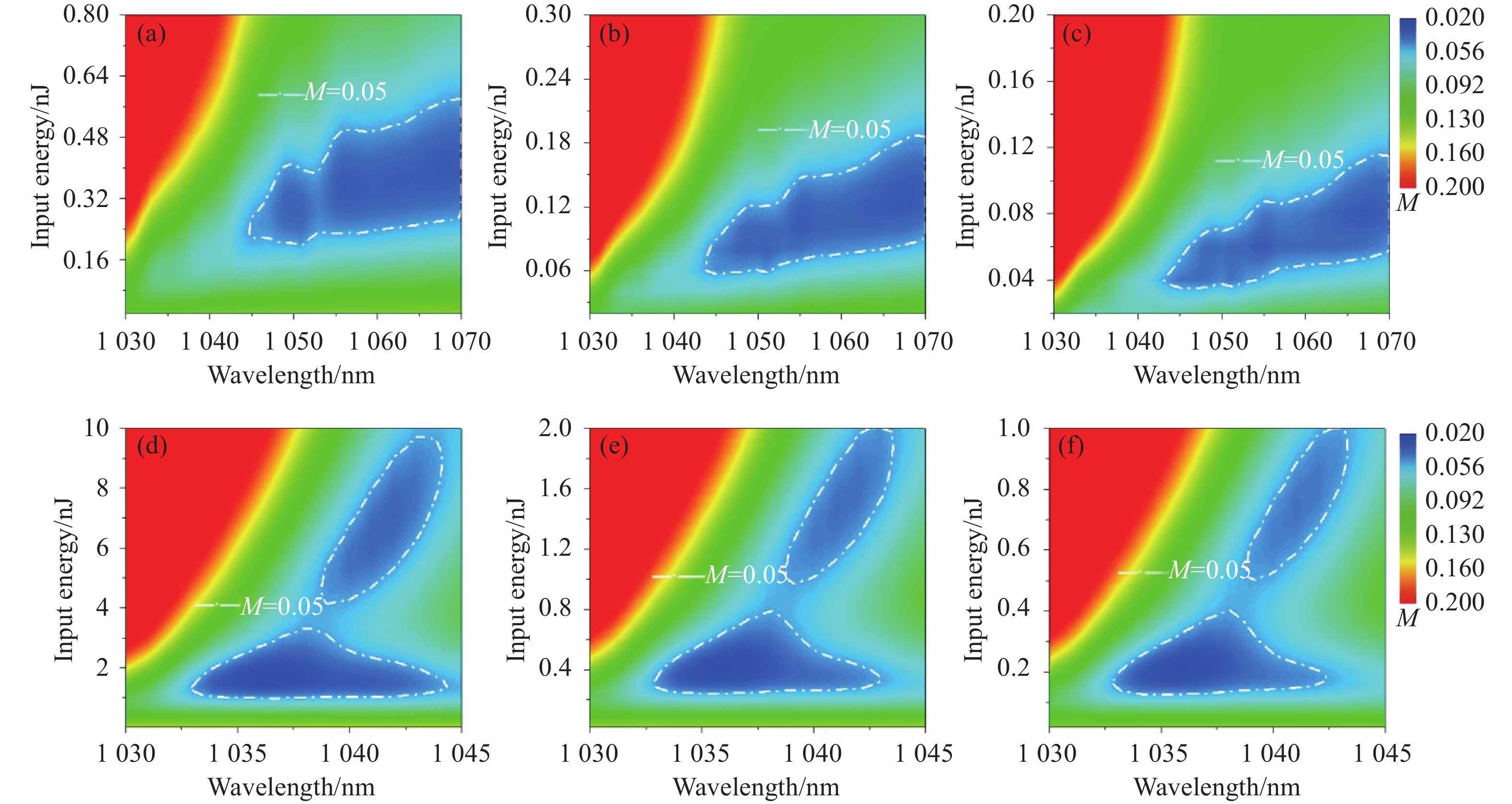
为了探究在不同增益光纤长度下增益分布对信号光脉冲自相似参数区域的影响,将增益总系数固定为30 dB,增益光纤长度分别设为2 m、3 m和4 m,其他条件相同,如图6所示。为了方便分析,保证自相似区域连贯性,图中画出M=0.05的等高线。通过比较可以看出采用正向泵浦和反向泵浦时在不同光纤长度下呈现不同的规律性。
从图6(a)~(c)中可以看出,随着光纤长度不断增加,在正向泵浦下信号光脉冲的自相似区域逐渐向低入射能量和长波长方向偏移,区域的面积也不断缩小。产生这一现象的原因有以下几点:1) 随着增益光纤长度的增加,在保证总增益不变的前提下,光纤每段的增益系数减小。根据增益谱线的分布趋势[18],增益系数越小的位置增益谱线越平坦,信号光脉冲的中心波长越靠近长波长。2)对于正向泵浦方式,自相似演化速度要快于反向泵浦方式。当增益光纤较长时,正向泵浦方式沿光纤长度方向上的增益分布更加均匀,能量增益更加平缓,光谱展宽更加缓慢,避免光谱迅速展宽突破增益带宽的限制,使得自相似演化过快结束。这样,相比于短波长的信号光脉冲,中心波长较长的脉冲对应的增益谱更平坦,增益系数也更小,间接地使增益分布沿光纤方向更加平缓。3)根据前面对自相似放大过程的分析,无论是正向泵浦还是反向泵浦,脉冲都是在增益光纤的后半段光谱迅速展宽、M因子迅速减小,自相似演化加速。对于正向泵浦方式下脉冲在长增益光纤中演化,后半段的增益系数较小,为了保证增益与非线性的平衡,需要脉冲具有较小的非线性效应,所以脉冲能量要尽量低,这样信号光脉冲对于入射能量的需求降低。而且较低的信号光脉冲能量也使得后半段的增益饱和效应相对较弱,使增益的作用更加明显。
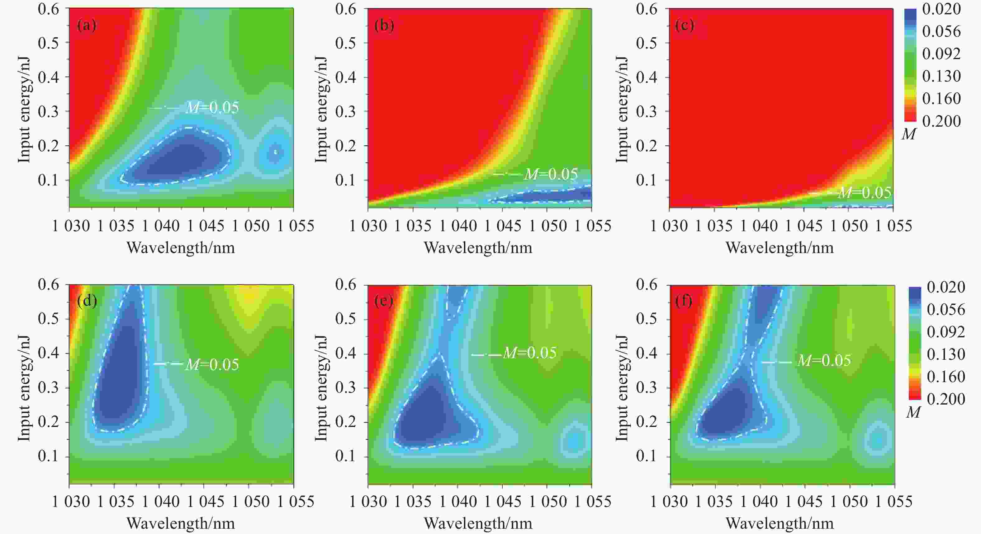
图 6 不同光纤长度下,放大脉冲的M因子与脉冲的中心波长和入射能量的关系。正向泵浦方式下,在(a) 2 m,(b) 3 m,(c) 4 m的光纤长度下放大脉冲的M因子伪彩图;反向泵浦方式下,在(d) 2 m,(e) 3 m,(f) 4 m的光纤长度下放大脉冲的M因子伪彩图
Figure 6. M-factors versus central wavelength and input energy of amplified pulses in different pump schemes with different fiber lengths. In forward-pumping scheme, the M-factors of amplified pulses with the fiber length of (a) 2 m, (b) 3 m, (c) 4 m. In backward-pumping scheme, the M-factors of amplified pulses with the fiber length of (d) 2 m, (e) 3 m, (f) 4 m
图6(d)~(f)可以看出,随着光纤长度的不断增加,反向泵浦下的信号光脉冲自相似区域逐渐向高入射能量方向延伸,但中心波长范围基本处于短波方向不变。这是因为反向泵浦方式下,脉冲能量的增长与反转集居数密度的增加是同步的。因此,当增益光纤较长时,增益光纤后半段的增益作用不会明显减弱,与非线性的平衡关系也不会被破坏。这样,短增益光纤与长增益光纤对反向泵浦而言区别不大。
通过纵向对比图6(a)和(d)、(b)和(e)、(c)和(f),对于同一光纤长度,不同泵浦方式下的自相似演化区域截然不同。正向泵浦方式下,信号光脉冲的自相似区域中心波长的范围更广,但入射能量的范围较窄;反向泵浦下,信号光脉冲的自相似区域中心波长范围较窄,但入射能量的范围较广。这是由于正向泵浦下脉冲在光纤前半段获得高增益,峰值功率迅速提升,获得较强的非线性效应,所以对初始入射能量十分敏感,宽容度较差;而反向泵浦下,脉冲在光纤前半段增益较低,峰值功率提升缓慢,获得的非线性较弱,所以对初始入射能量不敏感,宽容度较好。
(4) 总增益系数不同,增益光纤长度相同
为了探究在不同总增益系数下增益分布对信号光脉冲自相似参数区域的影响,将增益光纤长度固定为3 m,通过改变泵浦功率将总增益系数分别设为20 、25 、30 dB,其他条件相同,见图7。为了保证自相似区域的连贯性,图中画出M=0.05的等高线。
首先,对同种泵浦方式在不同的放大增益下进行横向对比(对比图7(a)、(b)、(c)或(d)、(e)、(f)),可以明显看出,无论是正向泵浦还是反向泵浦,在不同的总增益系数下自相似区域均呈现一定的规律性。当放大增益逐渐增大时,自相似区域逐渐向低入射能量方向移动,但中心波长区域不发生变化。这是因为当增益系数增加时,为了实现自相似演化过程,需要避免非线性光谱展宽过快而受到增益整形作用的影响,所以只能减小信号光的脉冲能量。同时,当放大增益逐渐减小时,自相似区域在入射能量方向的范围逐渐增大。这说明无论采用哪种泵浦方式,在低增益下对入射能量的宽容度都比在高增益下更好。

图 7 不同泵浦方式、不同总增益下放大脉冲的M因子与脉冲的中心波长和入射能量的关系。正向泵浦方式下,在(a) 20 dB,(b) 25 dB,(c) 30 dB的总增益下放大脉冲的M因子伪彩图;反向泵浦方式下,在(d) 20 dB,(e) 25 dB,(f) 30 dB的总增益下放大脉冲的M因子伪彩图
Figure 7. M-factors versus central wavelength and input energy of amplified pulses in different pump schemes with different total gain coefficients. In forward-pumping scheme, the M-factors of amplified pulses with the total gain coefficient of (a) 20 dB, (b) 25 dB, (c) 30 dB. In backward-pumping scheme, the M-factors of amplified pulses with the total gain coefficient of (d) 20 dB, (e) 25 dB, (f) 30 dB
-
文中通过建立以掺Yb3+光纤实际吸收与发射截面谱线为基础的自相似脉冲放大的数值模型,重点探究了皮秒脉冲在自相似放大过程中的演化特性与增益分布之间的联系,系统地对比了不同的增益分布对自相似放大系统过程和结果的影响。首先,在不同的增益分布下分别实现了皮秒脉冲的最佳自相似放大过程,得到了近变换极限的百飞秒高质量脉冲输出。其次,固定放大增益为30 dB,在2 m的掺Yb3+光纤中系统地探究了不同泵浦方式对皮秒脉冲在增益光纤中自相似演化过程的影响。结果表明,同一脉冲在增益光纤中演化至自相似放大过程时,正向泵浦方式下的演化速度更快,但容易受到增益整形的破坏而偏离自相似演化;反向泵浦方式下的演化速率稍慢,但不容易受到增益整形作用的破坏。最后,通过在不同的光纤长度和总增益系数条件下分别绘制放大脉冲M因子与中心波长和入射脉冲能量之间的关系伪彩图,探究了不同的增益分布对皮秒脉冲在增益光纤中自相似演化结果的影响。结果表明,正向泵浦方式下的信号光自相似区域主要集中在低入射脉冲能量和长波长区域;反向泵浦方式下的信号光自相似区域主要集中在高入射脉冲能量和短波长区域。无论采用哪种泵浦方式,在总增益较低时对脉冲入射能量的宽容度更好。所以,通过控制增益光纤中的增益分布可以实现皮秒脉冲的自相似放大,获得具有高时域质量的百飞秒脉冲输出。在具体实验和工业生产中,可以根据不同的参数(入射脉冲参数、增益光纤长度、泵浦功率等)选择合适的泵浦方式来实现不同的增益分布,获得高质量的飞秒量级脉冲输出,在医疗和军事等领域有良好的应用前景。
Effects of gain distribution on self-similar amplification of picosecond pulses
-
摘要: 采用数值模拟的方法,研究了增益分布对皮秒脉冲自相似放大的影响。构建了掺镱光纤内超短激光脉冲自相似放大的理论模型,以不同的泵浦方式、光纤长度和总增益系数实现不同的增益分布,探究了不同增益分布对增益光纤中皮秒脉冲的自相似放大过程和结果的影响。结果表明,皮秒脉冲在不同的增益分布下存在最佳的自相似放大结果,可以得到近变换极限的百飞秒高质量脉冲输出。发现同一信号光脉冲在增益光纤中演化至自相似放大过程时,正向泵浦方式下的演化速度比反向泵浦快。对于不同的增益光纤长度和总增益系数,正向泵浦方式下的信号光自相似区域主要集中在低入射脉冲能量和长波长区域,反向泵浦方式下的信号光自相似区域主要集中在高入射脉冲能量和短波长区域。Abstract: The effects of gain distribution on self-similar amplification of picosecond pulses in a Yb-doped fiber laser system were studied by numerical simulation. Ultrashort laser pulses amplified in self-similar amplification theoretical model was established to analyze the impact of pump configuration, fiber length and total gain coefficient on the self-similar amplification evolution and laser output performance. Detailed numerical simulation reveals that the best self-similar amplification result can be found for different cases, where high-quality self-similar pulses with ~100 fs transform-limited pulse duration are obtained. It is demonstrated that the self-similar evolution speed in a forward-pumping scheme is faster than that in a backward-pumping scheme for a fixed seed pulse. Furthermore, the results indicate that for the self-similar amplifier with different fiber lengths and gain coefficients, the forward-pumping scheme shows better evolution results in lower seed energy and longer wavelength range, while the backward-pumping scheme is more suitable for the higher seed energy and shorter wavelength range.
-
Key words:
- picosecond laser /
- self-similar amplification /
- fiber amplifier /
- gain distribution
-
图 1 自相似放大在不同泵浦方式下的示意图。(a)正向泵浦,(b)反向泵浦
Figure 1. Self-similar amplification in different pump schemes. (a) Forward pump, (b) backward pump
图 2 不同泵浦方式下放大脉冲的M因子与脉冲中心波长和入射能量关系的伪彩图。(a)正向泵浦,(b)反向泵浦。A和B点分别表示M值在(a)和(b)的最低点,即自相似演化的最佳点
Figure 2. M-factors versus pulse central wavelength and input energy of amplified pulses in different pump schemes. (a) Forward pump, (b) backward pump. Point A and B represent the minimum value of M-factors in (a) and (b), which are the best points of self-similar evolution
图 3 信号光脉冲在不同泵浦方式下的放大结果。(a) A点处的信号光脉冲在正向泵浦下传输到光纤2 m处的去啁啾时域强度,(b) B点处的信号光脉冲在反向泵浦下传输到光纤2 m处的去啁啾时域强度。黑色实线表示信号光脉冲,红色实线表示对应的变换极限脉冲。内插图分别为对应的光谱(左)和压缩前脉冲时域(右),其中黑线和红线代表信号光脉冲和抛物线拟合
Figure 3. Amplification results of seed pulses in different pump schemes. (a) De-chirped pulse profile of the seed pulse of point A transmitting to the end of the 2 m-long fiber in forward-pumping scheme, (b) de-chirped pulse profile of the seed pulse of point B transmitting to the end of the 2 m-long fiber in backward-pumping scheme. Black lines and red lines are seed pulses and transform-limited pulses. Insets: corresponding spectra (left) and amplified pulses before compression (right). Black lines and red lines are seed pulses and parabolic fittings
图 4 A点处的信号光脉冲在正、反泵浦方式下的演化过程。(a) 峰值功率(实线)与M因子(点划线),(b) 10 dB光谱宽度(实线)与脉冲宽度(点划线)。黑色曲线表示正向泵浦,红色曲线表示反向泵浦。(c) 正向泵浦下的光谱演化,(d) 反向泵浦下的光谱演化
Figure 4. Evolution of the seed pulse of point A in forward-pumping and backward-pumping schemes. (a) Peak power (solid) and M-factor (dash-dot), (b) 10 dB spectral width (solid) and pulse width(dash-dot). Black lines and red lines represent forward pump and backward pump. (c) Spectral evolution in forward-pumping scheme, (d) Spectral evolution in backward-pumping scheme
图 5 B点处的信号光脉冲在正、反泵浦方式下的演化过程。(a) 峰值功率(实线)与M因子(点划线),(b)10 dB光谱宽度(实线)与脉冲宽度(点划线),黑色曲线表示正向泵浦,红色曲线表示反向泵浦。(c) 正向泵浦下的光谱演化,(d) 反向泵浦下的光谱演化
Figure 5. Evolution of the seed pulse of point B in forward-pumping and backward-pumping schemes. (a) Peak power (solid) and M-factor(dash-dot), (b) 10 dB spectral width (solid) and pulse width(dash-dot). Black lines and red lines represent forward pump and backward pump. (c) Spectral evolution in forward-pumping scheme, (d) Spectral evolution in backward-pumping scheme
图 6 不同光纤长度下,放大脉冲的M因子与脉冲的中心波长和入射能量的关系。正向泵浦方式下,在(a) 2 m,(b) 3 m,(c) 4 m的光纤长度下放大脉冲的M因子伪彩图;反向泵浦方式下,在(d) 2 m,(e) 3 m,(f) 4 m的光纤长度下放大脉冲的M因子伪彩图
Figure 6. M-factors versus central wavelength and input energy of amplified pulses in different pump schemes with different fiber lengths. In forward-pumping scheme, the M-factors of amplified pulses with the fiber length of (a) 2 m, (b) 3 m, (c) 4 m. In backward-pumping scheme, the M-factors of amplified pulses with the fiber length of (d) 2 m, (e) 3 m, (f) 4 m
图 7 不同泵浦方式、不同总增益下放大脉冲的M因子与脉冲的中心波长和入射能量的关系。正向泵浦方式下,在(a) 20 dB,(b) 25 dB,(c) 30 dB的总增益下放大脉冲的M因子伪彩图;反向泵浦方式下,在(d) 20 dB,(e) 25 dB,(f) 30 dB的总增益下放大脉冲的M因子伪彩图
Figure 7. M-factors versus central wavelength and input energy of amplified pulses in different pump schemes with different total gain coefficients. In forward-pumping scheme, the M-factors of amplified pulses with the total gain coefficient of (a) 20 dB, (b) 25 dB, (c) 30 dB. In backward-pumping scheme, the M-factors of amplified pulses with the total gain coefficient of (d) 20 dB, (e) 25 dB, (f) 30 dB
-
[1] Yan Dongyu, Liu Bowen, Song Huanyu, et al. Research status and development trend of high power femtosecond fiber laser amplifiers [J]. Chinese Journal of Lasers, 2019, 46(5): 0508012. (in Chinese) doi: 10.3788/CJL201946.0508012 [2] Li Chen, Stoian Razvan, Cheng Guanghua. Laser-induced periodic surface structures with ultrashort laser pulse [J]. Chinese Optics, 2018, 11(1): 1-17. (in Chinese) [3] Wang Zhen, Fu Wenjing, Zhang Rongzhu. Numerical simulation of femtosecond laser multi-pulse ablation of metal iron [J]. Infrared and Laser Engineering, 2019, 48(7): 0706002. (in Chinese) doi: 10.3788/IRLA201948.0706002 [4] 飞秒激光抛光CVD金刚石涂层表面[J]. 光学精密工程, 2019, 27(1): 164-171. Ma Yuping, Zhang Yao, Wei Chao, et al. Surface polishing of CVD diamond coating by femtosecond laser[J]. Optics and Precision Engineering, 2019, 27(1): 164-171. (in Chinese) [5] Zheng Changbin, Shao Junfeng, Li Xuelei, et al. Femtosecond pulsed laser induced damage characteristics on Si-based multi-layer film [J]. Chinese Optics, 2018, 12(2): 371-381. (in Chinese) [6] Lu X, Zhang S, Jeon C G, et al. Time-of-flight detection of femtosecond laser pulses for precise measurement of large microelectronic step height [J]. Optics Letters, 2018, 43(7): 1447-1450. doi: 10.1364/OL.43.001447 [7] Pan Deng, Li Jiawen, Yang Liang, et al. Femtosecond laser holograpic fabrication of hydrogel cell scaffold [J]. Optics and Precision Engineering, 2017, 25(9): 2277-2282. (in Chinese) doi: 10.3788/OPE.20172509.2277 [8] Sun Shufeng, Wang Pingping. Micro/nano structures fabricated by two-photon photopolymerization of femtosecond laser [J]. Infrared and Laser Engineering, 2018, 47(12): 1206009. (in Chinese) doi: 10.3788/IRLA201847.1206009 [9] Matsui Y, Pelusi M D, Suzuki A. Generation of 20-fs optical pulses from a gain-switched laser diode by a four-stage soliton compression technique [J]. IEEE Photonics Technology Letters, 1999, 11(10): 1217-1219. doi: 10.1109/68.789696 [10] Ouzounov D G, Ahmad F R, Müller D, et al. Generation of megawatt optical solitons in hollow-core photonic band-gap fibers [J]. Science, 2003, 301(5640): 1702-1704. doi: 10.1126/science.1088387 [11] Yuan J, Chen J, Li F, et al. Mid-infrared self-similar compression of picosecond pulse in an inversely tapered silicon ridge waveguide [J]. Optics Express, 2017, 25(26): 33439-33450. doi: 10.1364/OE.25.033439 [12] Lavenu L, Natile M, Guichard F, et al. Nonlinear pulse compression based on a gas-filled multipass cell [J]. Optics Letters, 2018, 43(10): 2252-2255. doi: 10.1364/OL.43.002252 [13] Fermann M E, Kruglov V I, Thomsen B C, et al. Self-similar propagation and amplification of parabolic pulses in optical fibers [J]. Physical Review Letters, 2000, 84(26): 6010. doi: 10.1103/PhysRevLett.84.6010 [14] Kruglov V I, Peacock A C, Harvey J D, et al. Self-similar propagation of parabolic pulses in normal-dispersion fiber amplifiers [J]. Journal of the Optical Society of America B, 2002, 19(3): 461-469. doi: 10.1364/JOSAB.19.000461 [15] Dudley J M, Finot C, Richardson D J, et al. Self-similarity in ultrafast nonlinear optics [J]. Nature Physics, 2007, 3(9): 597. doi: 10.1038/nphys705 [16] Deng Y, Chien C Y, Fidric B G, et al. Generation of sub-50 fs pulses from a high-power Yb-doped fiber amplifier [J]. Optics Letters, 2009, 34(22): 3469-3471. doi: 10.1364/OL.34.003469 [17] Song H, Liu B, Chen W, et al. Femtosecond laser pulse generation with self-similar amplification of picosecond laser pulses [J]. Optics Express, 2018, 26(20): 26411-26421. doi: 10.1364/OE.26.026411 [18] Wang S, Liu B, Hu M, et al. Amplification and bandwidth recovery of chirped super-gaussian pulses by use of gain shaping in ytterbium-doped fiber amplifiers [J]. Journal of Lightwave Technology, 2014, 32(22): 3827-3835. [19] Finot C, Parmigiani F, Petropoulos P, et al. Parabolic pulse evolution in normally dispersive fiber amplifiers preceding the similariton formation regime [J]. Optics Express, 2006, 14(8): 3161-3170. doi: 10.1364/OE.14.003161 [20] Schimpf D N, Seise E, Limpert J, et al. Self-phase modulation compensated by positive dispersion in chirped-pulse systems [J]. Optics Express, 2009, 17(7): 4997-5007. doi: 10.1364/OE.17.004997 [21] Wang S, Liu B, Hu M, et al. On the efficiency of parabolic self-similar pulse evolution in fiber amplifiers with gain shaping [J]. Journal of Lightwave Technology, 2016, 34(13): 3023-3034. doi: 10.1109/JLT.2016.2557719 -

 点击查看大图

计量
- 文章访问数: 6035
- HTML全文浏览量: 2689
- PDF下载量: 98
- 被引次数: 0


