


-
With the constant esclation of modern warfare, the detonation control accuracy of missile, a weapon with great lethality and strong combat effective-ness, is required to be higher. However, the accuracy of detonation control information is not high due to the problem of insufficient data acquisition and low data utilization rate of traditional missile. Therefore, multi-mode data fusion method has been widely concerned. In order to improve the precision, more accurate detonation control data can be obtained by making full use of the information of seeker and fuze, so as to achieve precise strike. Literature [1] firstly introduces the infrared imaging guidance-laser ranging integrated fuze technology, and combines it with the aimable warhead, and determines the missile coordinate system and the mathematical model of the aimable warhead. On this basis, it establishes the fuze-warhead coordination model when the aimable warhead attacks sideways and intercepts the target forward, and proves the effectiveness of the integrated fuze and the aimable warhead coordination. Although the literature has successfully deduced the calculation model of the best initiation delay time and verified the conclusion that this integrated fuze initiation control method can improve the initiation control accuracy of integrated fuze, the information fusion process of two systems (seeker imaging system and laser rangefinder ranging system) in integrated fuze has not been described, and it is impossible to determine the influence of the measurement data accuracy of integrated fuze on the initiation control accuracy, so it is necessary to conduct in-depth study on this process. Literature [2] uses the digital system control method to realize the synchronous correlation of information between seeker imaging system and laser rangefinder, and proposes a centralized information fusion filtering algorithm for integrated fuze based on unscented Kalman filter. However, UKF algorithm is prone to collapse when dealing with complex problems, which is the defect of the algorithm itself. Therefore, this algorithm is mostly used in theoretical analysis at present. Literature [3] extracts the integrated information by using tracking differentiator, so as to obtain the angle and speed information needed to calculate the delay time of firing, but the asynchronous information time alignment method has higher requirements for the hardware mechanism on the missile. Literature [4] proposes an improved adaptive Kalman filter algorithm based on conversion measurement, which makes a more accurate estimation of the killing range and miss azimuth of the warhead, and realizes the asynchronous track fusion of heterogeneous sensors. The information fusion algorithm in literatures [5-7] is suitable for the case that the sampling time of multiple sensors can be aligned and the sampling period is an integer multiple. Therefore, according to the typical missile-target rendezvous process, the calculation model of initiation delay time is deduced. In view of the problems existing in the fusion process of asynchronous dual-mode sensors, a time alignment method based on interpolation and extrapolation [7] is given, and a data processing method based on improved filter is proposed, which improves the data accuracy and further improves the detonation control accuracy.
-
Air defense missile with infrared seeker, laser ranging system and missile-borne computer moves at high speed relative to the target. Because the time of missile-target rendezvous is very short, the following conditions[8-11] can be assumed: (1) The flight speed of the missile and the target in the intersection is very high. It can be considered that the missile and the target are moving in a uniform straight line, and the direction of the speed vector is consistent with the direction of the respective axis; (2) The attacked part of the target is the axial part. When the missile intercepts the target forward, the integrated fuze will first detect the front position of the target; When the missile intercepts the target laterally, the integrated fuze will first detect the lateral position of the target; (3) The initial velocity of warhead fragment is
${v_0}$ , and the velocity decays in the atmosphere and remains at${v_0}$ all the time. The typical missile-target rendezvous scene is shown in Figure 1.
Figure 1. Typical missile-target rendezvous scene
In the figure, R is the relative movement distance of missile and target,
$\phi $ is the azimuth angle of target relative to missile,$\theta $ is the fuze detection angle,${V_R}$ is the relative movement speed, T is the tracking point target aimed by infrared seeker, and J is the intersection position of fragment and target. The missile moves in the forward direction along the$O{X_b}$ axis(that is, the longitudinal axis of the missile)in the missile coordinate system. Assuming that the missile is stationary in the missile coordinate system, the target moves in the direction of missile along TJ with relative speed${V_R}$ .When that pixel number of the target image captured by the seeker is proportional to the pixel number of the seeker detection device, that is, the seeker is about to get out of control and turn to local tracking [1]. In order to give the working time of the laser rangefinder, it is necessary to calculate the remaining flight time
${t_1}$ . Because the missile-target relative motion speed is fast and the rendezvous time is short in this missile-target rendezvous model, it is approximately considered that the components of the relative motion speed on three coordinate axes are constant vectors.${t_1}$ is calculated as follows:$$ t_{1}=\dfrac{1}{-\dfrac{\dot q}{2 q}+\theta \tan \theta} $$ (1) where,
$q=\dfrac{1}{\sqrt{\theta^{2}+\phi^{2} \sin ^{2} \theta}}$ .The laser ranging system can provide the missile-borne computer with the distance sequence between the missile and the target measured by the laser rangefinder, and the infrared seeker can provide the missile-borne computer with the angle and angular velocity information during the missile movement. The missile-borne computer can obtain the relative movement distance R and the relative velocity
${V_R}$ of the missile-target in the missile-target intersection by fusing the two data.In the projectile coordinate system, the relative motion distance and relative velocity at each sampling point are expressed as follows:
$$ \begin{split} \vec{R}_{i}=&\left[R_{x i}, R_{y i}, R_{z i}\right]^{{\rm{T}}} =\\ &\left[R_{i} \cos \theta_{i}, R_{i} \sin \theta_{i} \cos \phi_{i}, R_{i} \sin \theta_{i} \sin \phi_{i}\right]^{{\rm{T}}} \end{split} $$ (2) $$ \begin{split} \vec{V}_{R}=&\left[V_{Rxi}, V_{Ryi}, V_{Rzi}\right]^{{\rm{T}}}\cdot\\ &\left[\frac{\left(R_{x(i-1)}-R_{x i}\right)}{T_{i}},\dfrac{\left(R_{y(i-1)}-R_{y i}\right)}{T_{i}}, \dfrac{\left(R_{z(i-1)}-R_{z i}\right)}{T_{i}}\right]^{{\rm{T}}} \end{split} $$ (3) where, i=1,2,···,n, n is the number of sampling points obtained by the infrared laser ranging system sensor before the seeker loses control, Ti is the sampling period of the ranging system; Rxi, Ryi, Rzi and VRxi, VRyi, VRzi are the components of the missile-target relative distance R and the relative velocity
$ {V_R} $ at the i-th sampling point on the three coordinate axes of the missile coordinate system.The missile-target intersection is located in the
$ Y_{b} O Z_{b} $ plane, so the remaining flight time is calculated as follows:$$ t_{1 i}=\frac{R_{x{i}}}{V_{R xi}}=\frac{R_{i} \cos \theta_{i}}{\left(R_{(i-1)} \cos \theta_{(i-1)}-R_{i} \cos \theta_{i}\right) / T} $$ (4) Detonation control delay time
$ \tau $ is calculated as follows:$$ \tau=t_{1 n}-\left(\mid OJ \mid / V_{f}\right) $$ (5) Because the data of integrated fuze used in the above model is obtained at the same time between seeker imaging system and laser ranging system, in order to obtain integrated data information, it is necessary to align the angle information measured by seeker with the distance information measured by laser rangefinder.
-
The infrared seeker obtains the infrared image sequence of the target and the angle information in the missile-target motion model by processing the infrared image of the target, obtains the distance information between the missile and the target by the laser ranging system, and then obtains the initiation signal and initiation orientation by processing the information with the onboard computer. The parallel processing mechanism of the centralized fusion system is used to obtain the guidance and control integration information as shown in Figure 2.

Figure 2. Flow chart of signal
-
Interpolation and extrapolation method[12] uses time slice technology to calculate the high-frequency observation data measured by passive sensors to the time point of low-frequency data measured by active sensors, that is, in the same time slice, the observation data of each sensor are sorted incrementally according to the measurement frequency, and then the high-frequency observation data are interpolated and extrapolated to the low-frequency time point to form observation data with equal intervals. In this paper, because the sampling frequency of the two sensors is quite different, the interpolation method is used to achieve data alignment[13].
Assume that the measured data at the time
${t_{ki - 1}},{t_{ki}},{t_{ki + 1}}$ are${z_{i - 1}},{z_i},{z_{i + 1}}$ , and sampling time interval:${t_{ki + 1}} - {t_{ki}} = {t_{ki}} - {t_{ki - 1}} = h$ . Assuming that the sampling point time is${t_i}$ , and${t_i} = {t_{ki}} + \tau h$ , the measured value of sampling point time${t_i}$ calculated by linear interpolation method is:$$ \begin{gathered} {{\bar z}_i} = \frac{{({t_i} - {t_{ki}})({t_i} - {t_{ki + 1}})}}{{({t_{ki - 1}} - {t_{ki}})({t_{ki - 1}} - {t_{ki + 1}})}}{z_{i - 1}} + \hfill \\ \frac{{({t_i} - {t_{ki - 1}})({t_i} - {t_{ki}})}}{{({t_{ki + 1}} - {t_{ki - 1}})({t_{ki + 1}} - {t_{ki}})}}{z_{i + 1}} + \hfill \\ \frac{{({t_i} - {t_{ki - 1}})({t_i} - {t_{ki + 1}})}}{{({t_{ki}} - {t_{ki - 1}})({t_{ki}} - {t_{ki + 1}})}}{z_i} \hfill \\ \end{gathered} $$ (6) In this paper, the time point of laser ranging information is aligned with the time point of seeker infrared imaging angle measurement information, and then the asynchronous sensor information time alignment is realized.
-
The measurement information of laser rangefinder and infrared imaging system after time alignment is used to estimate the target state, so as to obtain the state quantity to realize the best initiation control.
At the ballistic terminal, it is assumed that the target moves in a uniform linear motion relative to the missile, so the state equation of the target aiming point is that the target moves in a uniform linear motion. Assuming the target state variable
$X = {[x,y,z,\dot x,\dot y,\dot z]^{\rm T}}$ , the obtained state equation of the target aiming point is:$$ K(k+1)=F K(k)+G W(k) $$ (7) Using the synchronized measurement data, the system measurement model is obtained as follows:
$$ \begin{gathered} Z(k) = \left[ {\begin{array}{*{20}{c}} {R(k)} \\ {\theta (k)} \\ {\varphi (k)} \end{array}} \right] \hfill = \left[ {\begin{array}{*{20}{c}} {\sqrt {{x^2}(k) + {y^2}(k) + {z^2}(k)} } \\ {\arctan \left(\dfrac{{\sqrt {{y^2}(k) + {z^2}(k)} }}{{x(k)}}\right)} \\ {\arctan \left(\dfrac{{z(k)}}{{y(k)}}\right)} \end{array}} \right] + V(k) \hfill \\ \end{gathered} $$ (8) where,
$ V(k) $ is the measurement error of the sensor.In integrated fuze system model, the motion equation (system state equation) of the tracked aiming point of the intercepted target is linear, while the measurement equation of the system is a nonlinear function, so this problem is a nonlinear filtering problem. Because particle filter can give the best approximate solution of state estimation which is closest to Bayesian filter under complex background noise, the background is complex in typical missile target rendezvous scenarios, especially under the condition of unknown noise statistical characteristics, using particle filter can achieve better prediction results.
The algorithm is as follows:
Initialization, importance function, particle, particle weight
$$ q\left(x_{0}\right),\left\{x_{0}^{(i)}\right\}, w_{0}^{(i)}=\frac{p\left[z_{0} \mid x_{0}^{(i)}\right] \cdot p\left[x_{0}^{(i)}\right]}{q\left(x_{0}^{(i)} \mid z_{0}\right)} $$ (9) Time update: updating particle sets
$$ \left\{x_{k}^{(1)}\right\}, x_{k}^{(1)}=f\left[x_{k-1}(i)\right] $$ (10) Measurement update: Importance weights
$$ w_{k}^{(i)}=w_{k-1} \frac{(i)}{q\left[z_{k} \mid x_{k}^{(i)}\right] \cdot p\left[x_{k}^{(i)} \mid x_{k-1}^{(i)}\right]}{q\left(x_{x}^{(i)} \mid x_{x-1}^{(i)}, z_{k}\right)} $$ (11) Resampling, normalizing weights
$$ \left\{x_{k}^{(i)}\right\}, w_{k}^{(i)}=\frac{1}{N} $$ (12) State estimation
$$ \begin{aligned} x_{k}= &\sum_{i=1}^{N} w_{k}^{(i)} x_{z}{ }^{(0)} q\left(x_{x} \mid z_{x}\right) =\\ &\sum_{i=1}^{N} w_{k}^{(i)} \delta\left[x_{z}-x_{x}{ }^{(i)}\right] \end{aligned} $$ (13) -
Because of the fast relative movement speed and short encounter time of missile and target at the intersection stage, the result of data processing will directly affect the detonation control accuracy, which is particularly important for the integrated system of guidance and control [1]. Taking the influence of detection angle of integrated fuze on delay time as an example.
Typical missile-target rendezvous scene[14-17]: taking the active equipment of the foreign army as an example, the speed of the interceptor is set to 3 Ma (1 020 m/s) and the speed of the target to be intercepted to 1.6 Ma (544 m/s).
(1) When the interceptor is intercepting the target in the forward direction, the rendezvous angle of the missile and target is
${\text{13}}{{\text{5}}^ \circ }$ , the relative movement speed of the missile and target is 1456 m/s. The near-field detection distance of rangefinder in integrated fuze is 20 m. Considering the influence of the integrated fuze detection angle$\theta $ on the initiation delay time, the integrated fuze detection angle$\theta $ is increased from${{\text{0}}^ \circ }$ to${\text{9}}{{\text{0}}^ \circ }$ , and the miss-target azimuth is${{\text{0}}^ \circ }$ . The experimental results are shown in Figure 3(a).
Figure 3. Relation curve between detection angle and delay time from forward interception (a), lateral interception (b)
(2) When the interceptor is intercepting the target laterally, the rendezvous angle of the missile and the target is
${\text{4}}{{\text{5}}^ \circ }$ , the relative movement speed of the target is 743 m/s, and the near-field detection range of the integrated fuze is 20 m. When considering the effect of the integrated fuze detection angle$\theta $ on the initiation delay time, the integrated fuze detection angle$ \theta $ is increased from 0° to${\text{9}}{{\text{0}}^ \circ }$ , and the miss azimuth is${{\text{0}}^ \circ }$ . The experimental results are shown in Figure 3(b).From Figure 3, we can get the following results:
(1) In the set typical interception scenario, the larger the detection angle, the smaller the initiation delay time and the less the reaction time left for the interceptor.
(2) When the missile intercepts the target in the forward direction, the initiation delay time curve is gentle, and the influence of detection angle change on initiation delay time is small; When the detection angle is behind, the initiation delay time curve and the influence of detection angle change on initiation delay time become larger.
Therefore, in order to improve the detonation control accuracy, it is necessary to reduce the detection angle error.
-
Matlab is used for simulation, and the traditional extended Kalman filter data processing method is compared with the improved particle filter method.
Parameter selection: distance observation noise variance is 0.01 m, missile-target intersection distance is 100 m, missile-target relative velocity is 1 456.4 m/s, and angle observation noise variance is
${\text{0}}{\text{.0}}{{\text{1}}^ \circ }$ . The simulation results are shown in Figures 4-9.
Figure 4. Detection angle and error

Figure 5. Azimuth angle and error
Figure 6. Delay time and error

Figure 7. Detection angle error

Figure 8. Azimuth angle error
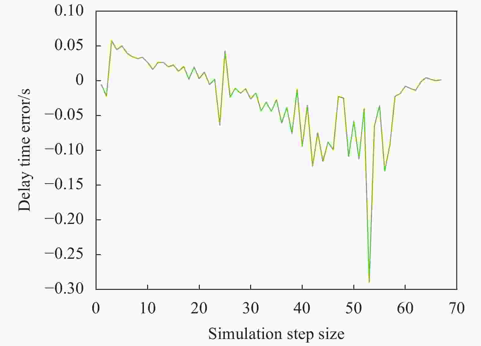
Figure 9. Delay time error
Figures 4-6 show the estimation errors based on the improved particle filter algorithm, and Figures 7-9 show the estimation errors based on the extended Kalman filter algorithm.
(1) From the tracking curves in Figures 4, 5, the tracking real-time performance based on the improved particle filter algorithm is better. In Figure 5, when the angle changes suddenly, it can still track in time, which proves that the algorithm has high reliability.
(2) From the error curves measured from the angles in Figures 4, 5, error mutation will occur only at limited points based on the improved particle filter algorithm. The peak value of this error mutation is very small and the error fluctuation is very small.
(3) Comparing the error curves in Figures 4, 5 and Figures 7, 8, it can be seen that the estimation error based on the improved particle filter algorithm is much smaller than that based on the extended kalman filter algorithm, and the error amplitude fluctuates very little.
(4) It can be seen from the simulation results of delay time in Figure 6 and Figure 9 that, under the same noise, although the estimated error of delay time tends to zero, the algorithm based on particle filter has smaller data fluctuation and better algorithm stability.
Because of the high precision of the obtained data, the detonation control precision of the integrated fuze is improved. Specific comparison results are shown in Table 1.
Table 1. Algorithm comparison
Algorithm RMSE of detection angle measurement/(°) RMSE of azimuth angle measurement/(°) RMSE of
delay time
t/msPF 0.0055 0.0144 0.7447 EKF 1.0781 0.7440 1.50411 From the data in Table 1, it can be seen from the data in Table 1 that the detection angle accuracy based on particle filter algorithm is improved by 99.49%, the azimuth angle accuracy is improved by 98.06%, and the delay time accuracy is improved by 95.05% due to the improvement of angle accuracy. Therefore, the data fusion method proposed in this paper is practical and effective.
-
Firstly, this paper analyzes the integrated fuze centralized information fusion system, realizes the data alignment of integrated fuze seeker imaging system/laser rangefinder measurement information by using digital alignment technology, and presents an integrated fuze centralized information fusion tracking algorithm based on improved particle filter. The simulation results show that under this method, the detection angle accuracy of integrated fuze is improved by 99.49%, the azimuth angle accuracy is improved by 98.06%, and the delay time accuracy is improved by 95.05%, which shows that this method can effectively reduce the error caused by measurement angle noise, thus improving the fuze in complex background.
In order to significantly improve the killing accuracy of missiles, it is necessary to obtain more accurate information of missile-target rendezvous. If the integrated fuze can make use of the abundant target information and missile-target intersection information provided by the guidance and control system, it can realize the prediction and estimation of fuze initiation control, and then realize the accurate initiation of missiles. Therefore, how to make full use of the guidance system to obtain more characteristic information of damaged targets (RCS characteristics, target vulnerability) and make information fusion estimation to achieve higher efficiency of fuze-warhead coordination will be the focus of the next research work.
-
摘要: 为了提高防空导弹引信的起爆控制精度,即得到更为准确的起爆延迟时间,提出了一种基于粒子滤波的红外成像导引头以及激光测距仪测量数据的一体化信息融合方法。在对多模信息进行处理时,由于不同传感器的开机时间和采样频率的不同造成了两传感器的测量数据不在同一个时间基准上,所以,选择在典型弹目交会的环境下,针对激光测距仪的高频采样与红外导引头的低频采样,使用了一种基于线性插值法的量测数据的时间对准方法,从而将传感器测量所得数据应用到延迟时间模型的计算中去。在该模型的基础上,提出了一种基于粒子滤波的一体化传感器集中式数据滤波算法,并通过与传统扩展卡尔曼滤波算法的对比仿真实验得到:在该信息融合方法下,得到的探测角、方位角测量精度均有较大提高,起爆延迟时间的精度因此也得到了提高,从而验证了论文中所提数据融合方法的有效性。Abstract: In order to improve the detonation control accuracy of the air defense missile fuze, that is, to obtain a more accurate detonation delay time, an integrated information fusion method for the measured data of infrared imaging seeker and laser rangefinder based on particle filter was proposed. When processing multi-mode information, the measurement data of the two sensors are not on the same time reference due to the different power-on time of different sensors and the difference in sampling frequency. Therefore, the typical missile target rendezvous scenarios were chosen, for the high-frequency sampling of the laser rangefinder and the low-frequency sampling of the infrared seeker, a time alignment method based on linear interpolation was used to apply the measured data to the calculation of delay time model. On the basis of this model, a centralized data filtering algorithm for integrated sensors based on particle filtering was proposed. It is obtained through a comparison simulation experiment with the traditional extended Kalman filtering algorithm: the measurement accuracy of detection angle and azimuth angle are greatly improved under this information fusion method, and the accuracy of detonation delay time is also improved, which verifies the effectiveness of the data fusion method proposed in this paper.
-
Figure 3. Relation curve between detection angle and delay time from forward interception (a), lateral interception (b)
Table 1. Algorithm comparison
Algorithm RMSE of detection angle measurement/(°) RMSE of azimuth angle measurement/(°) RMSE of
delay time
t/msPF 0.0055 0.0144 0.7447 EKF 1.0781 0.7440 1.50411  下载: 导出CSV
-
[1] Xu Junfeng, Jiang Chunlan, Mao Liang, et al. Coordination technology of ranging-imaging guidance integrated fusing and aimable warhead [J]. Infrared and Laser Engineering, 2014, 43(6): 1794-1800. (in Chinese) [2] Wen Yinfang, Wang Qiong. Research on GIF information fusion technology of air-to-air missile [J]. Computer Simulation, 2016, 33(4): 67-70, 90. (in Chinese) [3] Sun Bo, Jia Jingping, Zheng Jianqiang, et al. The research on infrared imaging GIF technology of ground-to-air missile [J]. Journal of Projectiles Rockets, Missiles and Guidance, 2013, 33(1): 57-60. (in Chinese) [4] Liu Jianfeng, Zhuang Zhihong, Liu Hong. Application research of converted measuring Kalman filter used in burst control technology of missile [J]. Journal of Electronics & Information Technology, 2005(9): 1388-1392. (in Chinese) [5] Wang Xiaohua, Jing Zhongliang, Chen Fei, et al. Activepassive joint tracking with infrared and laser sensors [J]. Infrared and Laser Engineering, 2001, 30(4): 219-225. (in Chinese) [6] Qi Guoqing, Sheng Andong, Liu Yan, et al. A method to improve the accuracy of air route estimation by using angle measurement information [J]. Acta Armamentarii, 2005, 2: 260-262. (in Chinese) [7] Yang Kai, Yang Wei, Shi Deqian, et al. A new tracking filtering algorithm combined infrared sensor with laser [J]. Journal of Gun Launch & Control, 2011(2): 86-89. (in Chinese) [8] Huang Zhengzhong, Cao Liangcai. Bicubic interpolation and extrapolation iteration method for high resolution digital holographic reconstruction [J]. Optics and Lasers in Enginee-ring, 2020, 130: 106090. (in Chinese) doi: https://doi.org/10.1016/j.optlaseng.2020.106090 [9] Li Yuzhao, Liu Yan, Chen Xi, et al. Precision analyses of point-of-burst control based on laser fuze [J]. Infrared and Laser Engineering, 2018, 47(12): 1206004. (in Chinese) doi: 10.3788/IRLA201847.1206004 [10] Wang Jinkui, Lou Wenzhong, Liu Weitong, et al. Integrated design of guidance law, fuze and warhead for maneuvering target interception [J]. Acta Armamentarii, 2020, 41(4): 649-655. (in Chinese) [11] Meng Lu, Yang Xu. A survey of object tracking algorithms [J]. Acta Automatica Sinica, 2019, 45(7): 1244-1260. (in Chinese) [12] Chen Zhimin, Wu Panlong, Bo Yuming, et al. Adaptive control bat algorithm intelligent optimization particle filter for maneuvering target tracking [J]. Acta Electronica Sinica, 2018, 46(4): 886-894. (in Chinese) [13] Wang Min, Xu Wenqing. Infrared small target tracking algorithm based on multi-feature and evaluation model [J]. Journal of Huazhong University of Science and Tech-nology(Natural Science Edition), 2017, 45(10): 1-6. (in Chinese) doi: 10.13245/j.hust.171001 [14] Cai Kerong, Yu Yao, Gao Zhilin, et al. Research on application of laser fuze for efficient fuze-warhead coordination in the air-defense missile [J]. Infrared and Laser Engineering, 2020, 49(4): 0403002. (in Chinese) doi: 10.3788/IRLA202049.0403002 [15] Zhang Cong, Li Dongguang. Mechanical and electronic video stabilization strategy of mortars with trajectory correction fuze based on infrared image sensor [J]. Sensors, 2020, 20(9): 2461. doi: https://doi.org/10.3390/s20092461 [16] Yu Yuting, Shu Jingrong, Ding Bosheng. Design of fuze-warhead coordination based on laser fuze and prefabricated fragment ammunition [J]. Infrared and Laser Engineering, 2018, 47(3): 0303003. (in Chinese) doi: 10.3788/IRLA201847.0303003 [17] Liu Bohu, Song Chengtian, Duan Yabo. Design and simulation of a panoramic laser imaging fuze [J]. Infrared and Laser Engineering, 2018, 47(4): 0406003. (in Chinese) doi: 10.3788/IRLA201847.0406003 -

 点击查看大图

图(9) / 表(1)
计量
- 文章访问数: 325
- HTML全文浏览量: 99
- PDF下载量: 31
- 被引次数: 0


